US1854425A - Continuous cooling ice box - Google Patents
Continuous cooling ice box Download PDFInfo
- Publication number
- US1854425A US1854425A US346566A US34656629A US1854425A US 1854425 A US1854425 A US 1854425A US 346566 A US346566 A US 346566A US 34656629 A US34656629 A US 34656629A US 1854425 A US1854425 A US 1854425A
- Authority
- US
- United States
- Prior art keywords
- ice
- drawers
- ice box
- continuous cooling
- compartment
- Prior art date
- Legal status (The legal status is an assumption and is not a legal conclusion. Google has not performed a legal analysis and makes no representation as to the accuracy of the status listed.)
- Expired - Lifetime
Links
- 238000001816 cooling Methods 0.000 title description 6
- XLYOFNOQVPJJNP-UHFFFAOYSA-N water Substances O XLYOFNOQVPJJNP-UHFFFAOYSA-N 0.000 description 11
- 238000009413 insulation Methods 0.000 description 3
- 230000008093 supporting effect Effects 0.000 description 3
- XEEYBQQBJWHFJM-UHFFFAOYSA-N Iron Chemical compound [Fe] XEEYBQQBJWHFJM-UHFFFAOYSA-N 0.000 description 2
- 238000002844 melting Methods 0.000 description 2
- 230000008018 melting Effects 0.000 description 2
- 238000005057 refrigeration Methods 0.000 description 2
- 230000006978 adaptation Effects 0.000 description 1
- 238000010276 construction Methods 0.000 description 1
- 239000007799 cork Substances 0.000 description 1
- 238000009408 flooring Methods 0.000 description 1
- 235000013305 food Nutrition 0.000 description 1
- 238000009434 installation Methods 0.000 description 1
- 229910052742 iron Inorganic materials 0.000 description 1
- 239000007788 liquid Substances 0.000 description 1
- 239000002184 metal Substances 0.000 description 1
- 229910052751 metal Inorganic materials 0.000 description 1
- 238000000034 method Methods 0.000 description 1
- 239000008267 milk Substances 0.000 description 1
- 210000004080 milk Anatomy 0.000 description 1
- 235000013336 milk Nutrition 0.000 description 1
- 238000004321 preservation Methods 0.000 description 1
- 230000003014 reinforcing effect Effects 0.000 description 1
- 235000014214 soft drink Nutrition 0.000 description 1
Images
Classifications
-
- F—MECHANICAL ENGINEERING; LIGHTING; HEATING; WEAPONS; BLASTING
- F25—REFRIGERATION OR COOLING; COMBINED HEATING AND REFRIGERATION SYSTEMS; HEAT PUMP SYSTEMS; MANUFACTURE OR STORAGE OF ICE; LIQUEFACTION SOLIDIFICATION OF GASES
- F25D—REFRIGERATORS; COLD ROOMS; ICE-BOXES; COOLING OR FREEZING APPARATUS NOT OTHERWISE PROVIDED FOR
- F25D3/00—Devices using other cold materials; Devices using cold-storage bodies
- F25D3/02—Devices using other cold materials; Devices using cold-storage bodies using ice, e.g. ice-boxes
- F25D3/04—Stationary cabinets
-
- F—MECHANICAL ENGINEERING; LIGHTING; HEATING; WEAPONS; BLASTING
- F25—REFRIGERATION OR COOLING; COMBINED HEATING AND REFRIGERATION SYSTEMS; HEAT PUMP SYSTEMS; MANUFACTURE OR STORAGE OF ICE; LIQUEFACTION SOLIDIFICATION OF GASES
- F25D—REFRIGERATORS; COLD ROOMS; ICE-BOXES; COOLING OR FREEZING APPARATUS NOT OTHERWISE PROVIDED FOR
- F25D25/00—Charging, supporting, and discharging the articles to be cooled
- F25D25/02—Charging, supporting, and discharging the articles to be cooled by shelves
- F25D25/024—Slidable shelves
Definitions
- My invention relates to improvements in a continuous cooling ice box, and it more especially consists of the features pointed out in the annexed claims.
- the purpose ot' my invention is to provideV an ice bon of large capacity from which portions of ice may be retail-ed to individual customers without incurring the expense of delivery; that does not depend upon a circulaio tion of cold air as is usual in well known types of refrigerators; that secures continuous cooling ⁇ through the storage of cold water from the melting ice; that contrary to previous proposals in which the water from the melting ice was intend-ed to trickle over the objects to be cooled, the water encircles the objects; that in contrast to the trickle method stores the cold water in drawers wherein the articles, milk bottles, soft drinks, an d sealed containers are placed and remain in the water; that through these provisions an economy of refrigeration is secured which is not otherwise attainable with conventional types of ice boxes; that secures a steady degree ot cooling through the continuous circulation of the cold water; and that employs any desired means of insulation around the cooling chambers.
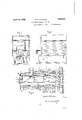
- Figure 1 is a front elevationof one of these large capacity ice boxes.
- Fig. 2 is a side elevation of l, showing th-e interior compartments by lines.
- Fig. 3 is a side elevation in section of cooling compartment.
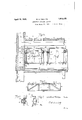
- Fig. l is an enlarged front elevation in section through a pair of water holding storage receptacles.
- Fig. 5 is a side elevation of a s A frame for the sliding storage receptacles drawers.
- Fig. 6 is an enlarged elevation in section Vdividual layers as to allow the melted of an anti-friction supporting wheel and tag cooperating parts.
- Fig. 7 1s a plan view of Fig. 6;
- a structurev l' represents' an enclosing cabinet which may be of any desired style or design.
- a lt has corner supports 2 which raise the structure from oil the floor.
- the space between'the supports 2- may be filled withlattice work 5.
- the cabinet is enclosed by sides 3, a roof ll, a rear wall and a front door 9. This encloses an icing section 8 and a cooled storage section 7 ln front of the door 9 of the icing compartment 8 a shelf 6 is provided which facilitates the serving of ice to individual customers.
- the icing compartment is of such capacity that a very large amount of ice can be placed in it at one time, thus concentrating intoa single large delivery what ordinarily would be peddled outin small quantities.
- rlhe iloor of the icing compartment is composed of fiat planks 15, usually of 2 X 8 stock, so as to support the great weight of the stored ice. These so-called joists laid tlatwise are spaced apart so as to permit the melted'ice to pass between them. 0n .top of the jois'ts l'narrower strips 17 are placed and crosswise-of these flooring slats 16 are laid. f
- rllhe parts 15, 16 and 17 are suiiiciently separated from each other in ⁇ respect of the inwater to freely fall into a collecting pan 18.
- This pan slopes forward as shown in Fig. 3. It may have openings 19 above each one of the drawers or storage receptacles 27; These openings are so positioned as to prevent any water coming ⁇ in contactwith the supportwheels 33, on which the drawers are positioned. 'lhe accumulating water will rise in the drawers 27 upto the height 37 of the overflow openings 29, from where it will fall on to a large drip panplaced beneath all of the drawers.
- This drip pan has sides 21, a rear lie' edge 22, and an inclined bottom 20. It has an outlet 23 which is connected to an ordinary trap 24:. Adjacent the outlet 23 the trap 24 passes through the sup-porting Hoor board 25.
- the drawers 27 may be made of galvanized iron with lengthwise reinforcing angles 28 placed along the top edges and along the length of the bottom corners.
- the angle bars placed lengthwise along the top edges serve to support the drawers ⁇ on anti-friction rollers 33.
- the front end ot the drawers is extended by reason of the insulation 30 placed between the external drawer front 1-Oand the drawer. Any suitable handle 31 may be attached to the drawer fronts for pulling the drawers in and out.
- the ⁇ drawer fronts 10 and the icing .door 9 may be provided with any desired form of gaskets.
- Each drawer is .supported on a pair of frames 26.
- These frames comprise lower angles 35 and upper angles 36 which are joined together in any suitable manner as exemplified in Fig. 5, and the frames 2G may be secured to the inside walls of the cabinet in any way desired.
- the lower angles 35 cooperate with the bottom corner angles of the drawers 23 to serve as a guide on which the drawers are moved.
- recesses 34 are formed as shown in Fig. 7 to constitute clearance room for the wheels 33.
- These wheels are supported on studs 32 which may be riveted into the upper members 36 and be provided with reduced diameters to form shoulders for the wheels and the securing nuts and washers in Vany desired manner.
- the inner walls 13 of the cabinet may be formed of boards, covered with a sheet metal lining, outside of which ordinary 2 x l studs may be placed on which the external sheathing 14 is secured. Between the inner walls 13 and the external sheathing 141 an insulating medium 12, such as cork or otherwise, is placed and this or a similar insulation may also be placed over the ceiling of the icing chamber. On the exterior of the simulated house, advertising panels 11 may be placed as shown in Figs. 1 and 2, and if desired the exterior walls 3 may be covered with ordinary siding. p
- the icing section 8 in addition to holding ice in larger or smaller portions to be retailed may in addition serve to hold sealed containers of any desired style or shape, which placed in direct contact with the ice or immediately adjacent to it will thereby increase the capacity of the ice box as a whole.
- certain food stuffs etc. may be placed in the icing section for preservation as desired. From this it is apparent that the ice box serves two interdependent purposes, relatively dry and liquid refrigeration.
- a suitable insulated cabinet comprising an ice containing compartment, a storage compartment, a floor in the icing compartment having openings therethrough, an inclined collecting pan beneath the floor having an outlet at its lowest point, a group of runways in the storage compartment, a sliding drawer positioned between a pair of runways, side projections lengthwise of the drawers, supporting wheels positioned on the runways on which the side projections rest, said drawers having limiting water level openings, a drip pan beneath the drawers, and an inclined bottom to the drip pan having an ⁇ outlet opening from the lowest point of the incline.
- an ice box comprising an ice containing compartment, a floor therein having openings therethrough, a storage compartment beneath the floor, insulating walls around both compartments, sliding drawers within the storage compartment adapted to hold water at a predetermined level, runways for .the drawers, an insulating front for each drawer, and an insulated door to the ice containing compartment.
Landscapes
- Engineering & Computer Science (AREA)
- Chemical & Material Sciences (AREA)
- Combustion & Propulsion (AREA)
- Physics & Mathematics (AREA)
- Mechanical Engineering (AREA)
- Thermal Sciences (AREA)
- General Engineering & Computer Science (AREA)
Description
i929 2 Sheets-Shea?l l PHILLIPS ONTINUOUS COOLING ICE BOX Filed March 13,
Filed March 13, 1929 2 sham-sheet 2 @mimi Patented Apr, 19, 1932 .n Pl
`WALTEB S. PHLLIPS, OF LAGRANGE, GEORGIA CONTINUOUS COOLNG ICE BOX Application filed March 13, y1929. Serial No. 346,566.
My invention relates to improvements in a continuous cooling ice box, and it more especially consists of the features pointed out in the annexed claims.
The purpose ot' my invention is to provideV an ice bon of large capacity from which portions of ice may be retail-ed to individual customers without incurring the expense of delivery; that does not depend upon a circulaio tion of cold air as is usual in well known types of refrigerators; that secures continuous cooling` through the storage of cold water from the melting ice; that contrary to previous proposals in which the water from the melting ice was intend-ed to trickle over the objects to be cooled, the water encircles the objects; that in contrast to the trickle method stores the cold water in drawers wherein the articles, milk bottles, soft drinks, an d sealed containers are placed and remain in the water; that through these provisions an economy of refrigeration is secured which is not otherwise attainable with conventional types of ice boxes; that secures a steady degree ot cooling through the continuous circulation of the cold water; and that employs any desired means of insulation around the cooling chambers.
With these and other ends in view, l illustrate in the accompanying drawings such instances of adaptation as will oiselose the broad underlying` features of my invention without limiting myself to the specific details shown thereon and described herein.
Figure 1 is a front elevationof one of these large capacity ice boxes.
Fig. 2 is a side elevation of l, showing th-e interior compartments by lines.
Fig. 3 is a side elevation in section of cooling compartment.
Fig. l is an enlarged front elevation in section through a pair of water holding storage receptacles.
Fig. 5 is a side elevation of a s A frame for the sliding storage receptacles drawers.
Fig. 6 is an enlarged elevation in section Vdividual layers as to allow the melted of an anti-friction supporting wheel and tag cooperating parts. i
Fig. 7 1s a plan view of Fig. 6;
ln practically carrying out lmy invention,
l may use whatever alternatives orequivalents of construction that the eXigencies of varying conditions of use and installation may require, without departing from the broad underlying spirit of mylinvention.
lin the example instanced in the drawings a structurev l'represents' an enclosing cabinet which may be of any desired style or design.A lt has corner supports 2 which raise the structure from oil the floor. The space between'the supports 2- may be filled withlattice work 5. The cabinet is enclosed by sides 3, a roof ll, a rear wall and a front door 9. This encloses an icing section 8 and a cooled storage section 7 ln front of the door 9 of the icing compartment 8 a shelf 6 is provided which facilitates the serving of ice to individual customers. The icing compartment is of such capacity that a very large amount of ice can be placed in it at one time, thus concentrating intoa single large delivery what ordinarily would be peddled outin small quantities. rlhe iloor of the icing compartment is composed of fiat planks 15, usually of 2 X 8 stock, so as to support the great weight of the stored ice. These so-called joists laid tlatwise are spaced apart so as to permit the melted'ice to pass between them. 0n .top of the jois'ts l'narrower strips 17 are placed and crosswise-of these flooring slats 16 are laid. f
The drawers 27 may be made of galvanized iron with lengthwise reinforcing angles 28 placed along the top edges and along the length of the bottom corners. The angle bars placed lengthwise along the top edges serve to support the drawers `on anti-friction rollers 33. The front end ot the drawers is extended by reason of the insulation 30 placed between the external drawer front 1-Oand the drawer. Any suitable handle 31 may be attached to the drawer fronts for pulling the drawers in and out. The `drawer fronts 10 and the icing .door 9 may be provided with any desired form of gaskets. Each drawer is .supported on a pair of frames 26.
These frames comprise lower angles 35 and upper angles 36 which are joined together in any suitable manner as exemplified in Fig. 5, and the frames 2G may be secured to the inside walls of the cabinet in any way desired. The lower angles 35 cooperate with the bottom corner angles of the drawers 23 to serve as a guide on which the drawers are moved. On the upper angles 36, recesses 34 are formed as shown in Fig. 7 to constitute clearance room for the wheels 33. These wheels are supported on studs 32 which may be riveted into the upper members 36 and be provided with reduced diameters to form shoulders for the wheels and the securing nuts and washers in Vany desired manner.
The inner walls 13 of the cabinet may be formed of boards, covered with a sheet metal lining, outside of which ordinary 2 x l studs may be placed on which the external sheathing 14 is secured. Between the inner walls 13 and the external sheathing 141 an insulating medium 12, such as cork or otherwise, is placed and this or a similar insulation may also be placed over the ceiling of the icing chamber. On the exterior of the simulated house, advertising panels 11 may be placed as shown in Figs. 1 and 2, and if desired the exterior walls 3 may be covered with ordinary siding. p
yIt is of course understood that the icing section 8 in addition to holding ice in larger or smaller portions to be retailed may in addition serve to hold sealed containers of any desired style or shape, which placed in direct contact with the ice or immediately adjacent to it will thereby increase the capacity of the ice box as a whole. In addition to receiving sealed containers certain food stuffs etc., may be placed in the icing section for preservation as desired. From this it is apparent that the ice box serves two interdependent purposes, relatively dry and liquid refrigeration.
What I claim is:
1. In an ice box, a suitable insulated cabinet comprising an ice containing compartment, a storage compartment, a floor in the icing compartment having openings therethrough, an inclined collecting pan beneath the floor having an outlet at its lowest point, a group of runways in the storage compartment, a sliding drawer positioned between a pair of runways, side projections lengthwise of the drawers, supporting wheels positioned on the runways on which the side projections rest, said drawers having limiting water level openings, a drip pan beneath the drawers, and an inclined bottom to the drip pan having an `outlet opening from the lowest point of the incline.
2. In an ice box comprising an ice containing compartment, a floor therein having openings therethrough, a storage compartment beneath the floor, insulating walls around both compartments, sliding drawers within the storage compartment adapted to hold water at a predetermined level, runways for .the drawers, an insulating front for each drawer, and an insulated door to the ice containing compartment.
In testimony whereof I aiiix my signature.
WALTER S. PHILLIPS.
lll!
Priority Applications (1)
| Application Number | Priority Date | Filing Date | Title |
|---|---|---|---|
| US346566A US1854425A (en) | 1929-03-13 | 1929-03-13 | Continuous cooling ice box |
Applications Claiming Priority (1)
| Application Number | Priority Date | Filing Date | Title |
|---|---|---|---|
| US346566A US1854425A (en) | 1929-03-13 | 1929-03-13 | Continuous cooling ice box |
Publications (1)
| Publication Number | Publication Date |
|---|---|
| US1854425A true US1854425A (en) | 1932-04-19 |
Family
ID=23360011
Family Applications (1)
| Application Number | Title | Priority Date | Filing Date |
|---|---|---|---|
| US346566A Expired - Lifetime US1854425A (en) | 1929-03-13 | 1929-03-13 | Continuous cooling ice box |
Country Status (1)
| Country | Link |
|---|---|
| US (1) | US1854425A (en) |
-
1929
- 1929-03-13 US US346566A patent/US1854425A/en not_active Expired - Lifetime
Similar Documents
| Publication | Publication Date | Title |
|---|---|---|
| US2271802A (en) | Refrigerated case | |
| US1854425A (en) | Continuous cooling ice box | |
| US2305075A (en) | Refrigerator car construction | |
| US1979625A (en) | Refrigerated display case | |
| US700721A (en) | Refrigerator-case. | |
| US2248286A (en) | Refrigerated display case | |
| US1854779A (en) | Refrigerator car | |
| US2031701A (en) | Cabinet construction | |
| US2147130A (en) | Floor rack for refrigerator cars | |
| US2073981A (en) | Refrigerator container for container cars | |
| US1873572A (en) | Refrigerator vehicle | |
| US1898560A (en) | Soda water fountain | |
| US1581156A (en) | Refrigerator show case | |
| US2225924A (en) | Refrigerator | |
| US1948275A (en) | Refrigerating apparatus | |
| US1948954A (en) | Refrigerator truck body | |
| US2275721A (en) | Refrigerator car construction | |
| US1589484A (en) | Refrigerator and ice container therefor | |
| US1067724A (en) | Refrigerator. | |
| US1513675A (en) | Ice box | |
| US933059A (en) | Refrigerator. | |
| USRE15819E (en) | Refbjgebator | |
| US1462436A (en) | Ice box for refrigerators | |
| US2321539A (en) | Refrigerator car construction | |
| US1949381A (en) | Railway refrigerator container |