US1854059A - Exercising device - Google Patents
Exercising device Download PDFInfo
- Publication number
- US1854059A US1854059A US445428A US44542830A US1854059A US 1854059 A US1854059 A US 1854059A US 445428 A US445428 A US 445428A US 44542830 A US44542830 A US 44542830A US 1854059 A US1854059 A US 1854059A
- Authority
- US
- United States
- Prior art keywords
- members
- horse
- motion
- cross rods
- springs
- Prior art date
- Legal status (The legal status is an assumption and is not a legal conclusion. Google has not performed a legal analysis and makes no representation as to the accuracy of the status listed.)
- Expired - Lifetime
Links
- 229910000746 Structural steel Inorganic materials 0.000 description 2
- 210000003205 muscle Anatomy 0.000 description 2
- 239000011435 rock Substances 0.000 description 2
- 230000009286 beneficial effect Effects 0.000 description 1
- 238000010276 construction Methods 0.000 description 1
- 230000003292 diminished effect Effects 0.000 description 1
- 235000000396 iron Nutrition 0.000 description 1
- 239000000463 material Substances 0.000 description 1
Images

Classifications
-
- A—HUMAN NECESSITIES
- A63—SPORTS; GAMES; AMUSEMENTS
- A63B—APPARATUS FOR PHYSICAL TRAINING, GYMNASTICS, SWIMMING, CLIMBING, OR FENCING; BALL GAMES; TRAINING EQUIPMENT
- A63B69/00—Training appliances or apparatus for special sports
- A63B69/04—Training appliances or apparatus for special sports simulating the movement of horses
Definitions
- lhis invention relates to improvements in exercising devices, and has particular reference to a device which simulates a horse and therefore gives the action of horseback ridwhich is sturdy in construction.
- a still further object is which which is neat in appearance and one takes up a minimum amount of room.
- Figure 1 is a side elevation of my device showing the horse and rider in dotted lines
- Figure 2 is a cross-sectional view taken on the line 22 of Figure 1, showing the horse in full lines, and
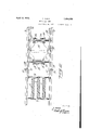
- Figure 3 is a fragmentary cross-sectional view taken on the line 33 of Figure 1, and on an enlarged scale.
- the numerals 5 and 6 designate angle iron members secured together at their ends by cross rods 7 to which a series of springs 8 are attached. The opposite ends of these springs are secured to sliding rods 9 which travel in slots 11 formed upon the angle iron members 5 and 6.
- Cross rods12 and 13 eX- tending between the angle irons 5 and 6 serve to support leaf spring standards 14 and 16, respectively. Carried upon the upper end of these standards are angles 17 and 18 which are pivoted thereto through the medium of the plate 28 to the 1930. ScrialNo. 445,428.' a
- Plates 23 and 24 are secured to the oppo- 7 site sides of the standards 14 and 16 and have a series of openings there-through, through which bolts 26 and 27. pass. Between the bolts 27 is positioned a plate 28 which carries a pivot pin 29 to which links 31 and 82 are pivoted. The opposite end of these links are slotted and engage the rods 9 at the opposite ends of the machine (see Figure 1). I
- a pair of handles 33 are pivoted to the' angles 5 and 6 as shown at 34: and extend to a point above the body of the horse so that the operator may readily grasp the same. These handles are connected by a cross member 36 which extends through the body of the horse. Stirrups 37 are provided for thefeet of the user.
- the device may be made to accommodate persons of difierent weight, or the amount of effort required to operate the device may be readily changed.
- the weight of the driver is thrown into the stirrups and an up and down motion given to the body as well as an arm motion, and consequently all of the muscles of body are brought into play.
- I claim 1 In a device of the character described, a pair of spaced supports, a pair of vertically disposed spring members capable of being flexed and connected to said support, a seat arrangement carried by said spring members and linkage connected to said spring members and extending in opposite directions therefrom, and other spring members secured to said linkage and said supports for yieldingly retaining said vertically disposed spring members in upright position.
- a pair of spaced angle members stationary cross rods extending between said angle members, slidable cross rods carried by said spaced members, springs secured to said stationary cross rods and having their opposite ends secured to said sliding cross rods, links connecting said sliding cross rods, a pair of fiat spring members vertically supported between s'aid angle members, a plate for retaining said flat spring members in their normal position, an occupant supporting surface connected to the upper end of said members and a pair of handles pivoted to said angle members and connected to said supporting surface and adapted to be grasped by the occupant of said device.
Landscapes
- Health & Medical Sciences (AREA)
- General Health & Medical Sciences (AREA)
- Physical Education & Sports Medicine (AREA)
- Rehabilitation Tools (AREA)
Description
April 12, 1932.
T. PARIS EXERCISING DEVICE Filed April 18, 1930 2 Sheets-Sheet INVENTOR.
.T PHRIS A ril- 12, 1932. T. PARLS 1,854,059
EXEHCISING DEVICE -Filed April 18, 1930 2 Sheets-Sheet 2 JNVEWOR.
T. F'FIRIS BY w m ATTORNEYS.
Patented Apr. 12, 1932 units!) STATES PATENT OFFICE THOMAS PARIS, 013 LOS ANGELES, CALIFORNIA EXEBCISING DEVICE Application filed April 18,
lhis invention relates to improvements in exercising devices, and has particular reference to a device which simulates a horse and therefore gives the action of horseback ridwhich is sturdy in construction.
to provide a device A still further object is which which is neat in appearance and one takes up a minimum amount of room.
Other objects and advantages will be apparent during the course of the following description. 7
In the accompanying drawings forming a part of this specification and in which like numerals are employed to designate like parts throughout the same,
Figure 1 is a side elevation of my device showing the horse and rider in dotted lines,
Figure 2 is a cross-sectional view taken on the line 22 of Figure 1, showing the horse in full lines, and
Figure 3 is a fragmentary cross-sectional view taken on the line 33 of Figure 1, and on an enlarged scale.
It is a well known ing is a very healthy fact that horseback rideXercise in that the riding motion brings into play all the muscles of the body. I have therefore produced a device wherein these beneficial qualities are present, and in the accompanying drawings the numerals 5 and 6 designate angle iron members secured together at their ends by cross rods 7 to which a series of springs 8 are attached. The opposite ends of these springs are secured to sliding rods 9 which travel in slots 11 formed upon the angle iron members 5 and 6. Cross rods12 and 13 eX- tending between the angle irons 5 and 6 serve to support leaf spring standards 14 and 16, respectively. Carried upon the upper end of these standards are angles 17 and 18 which are pivoted thereto through the medium of the plate 28 to the 1930. ScrialNo. 445,428.' a
A pair of handles 33 are pivoted to the' angles 5 and 6 as shown at 34: and extend to a point above the body of the horse so that the operator may readily grasp the same. These handles are connected by a cross member 36 which extends through the body of the horse. Stirrups 37 are provided for thefeet of the user.
In operation the user sits on the body ofthe horse with his feet in the stirrups and grasps the handles 33. By first pulling andthen pushing upon the handles, motion is transmitted to the body of the horse which causes it to rock upon the springs 14 and 16 which rocking motion is transmitted through links 31 and 82. These links impart motion to the cross rods 9, which motion is resisted by the springs 8. By adjusting the cross rods 7 in one of several of the holes in the angles 5 and 6, the tension of the springs 8 may be increased or diminished. Also by adjusting the pivotal connection between the pivot pin 29 and the openings formed in the ends of the links 31 and 32, various adjustments may be made. By raising the bolts 27 into any of the holes in the plates 23 and 24:, still further adjustment may be made of the device.
It will therefore be readily seen that by virtue of these various adjustments, the device may be made to accommodate persons of difierent weight, or the amount of effort required to operate the device may be readily changed. As the horse rocks back and forth the weight of the driver is thrown into the stirrups and an up and down motion given to the body as well as an arm motion, and consequently all of the muscles of body are brought into play.
It is to be understood that the form of my invention herewith shown and described is to be taken as a preferred example of the same and that various changes relative to the shape, size, material and arrangement of parts may be resorted to without departing from the spirit of the invention or the scope of the subjoined claims.
Having thus described my invention, I claim 1. In a device of the character described, a pair of spaced supports, a pair of vertically disposed spring members capable of being flexed and connected to said support, a seat arrangement carried by said spring members and linkage connected to said spring members and extending in opposite directions therefrom, and other spring members secured to said linkage and said supports for yieldingly retaining said vertically disposed spring members in upright position.
2. In a device of the character described, a pair of spaced angle members, stationary cross rods extending between said angle members, slidable cross rods carried by said spaced members, springs secured to said stationary cross rods and having their opposite ends secured to said sliding cross rods, links connecting said sliding cross rods, a pair of fiat spring members vertically supported between s'aid angle members, a plate for retaining said flat spring members in their normal position, an occupant supporting surface connected to the upper end of said members and a pair of handles pivoted to said angle members and connected to said supporting surface and adapted to be grasped by the occupant of said device.
In testimony whereof I afi'ix my signature.
THOMAS PARIS.
Priority Applications (1)
| Application Number | Priority Date | Filing Date | Title |
|---|---|---|---|
| US445428A US1854059A (en) | 1930-04-18 | 1930-04-18 | Exercising device |
Applications Claiming Priority (1)
| Application Number | Priority Date | Filing Date | Title |
|---|---|---|---|
| US445428A US1854059A (en) | 1930-04-18 | 1930-04-18 | Exercising device |
Publications (1)
| Publication Number | Publication Date |
|---|---|
| US1854059A true US1854059A (en) | 1932-04-12 |
Family
ID=23768859
Family Applications (1)
| Application Number | Title | Priority Date | Filing Date |
|---|---|---|---|
| US445428A Expired - Lifetime US1854059A (en) | 1930-04-18 | 1930-04-18 | Exercising device |
Country Status (1)
| Country | Link |
|---|---|
| US (1) | US1854059A (en) |
Cited By (5)
| Publication number | Priority date | Publication date | Assignee | Title |
|---|---|---|---|---|
| US2560436A (en) * | 1950-03-25 | 1951-07-10 | Green Martin | Ridable amusement and exercising device |
| US2785732A (en) * | 1954-05-07 | 1957-03-19 | Ben F Prewitt | Hobby horse |
| US3417990A (en) * | 1966-09-14 | 1968-12-24 | Marasco Vincent | Child's toy |
| US3432164A (en) * | 1967-02-14 | 1969-03-11 | Hugh A Deeks | Exercising machine |
| US5180338A (en) * | 1990-08-27 | 1993-01-19 | Pinto Albert A | Riding toy mechanism |
-
1930
- 1930-04-18 US US445428A patent/US1854059A/en not_active Expired - Lifetime
Cited By (5)
| Publication number | Priority date | Publication date | Assignee | Title |
|---|---|---|---|---|
| US2560436A (en) * | 1950-03-25 | 1951-07-10 | Green Martin | Ridable amusement and exercising device |
| US2785732A (en) * | 1954-05-07 | 1957-03-19 | Ben F Prewitt | Hobby horse |
| US3417990A (en) * | 1966-09-14 | 1968-12-24 | Marasco Vincent | Child's toy |
| US3432164A (en) * | 1967-02-14 | 1969-03-11 | Hugh A Deeks | Exercising machine |
| US5180338A (en) * | 1990-08-27 | 1993-01-19 | Pinto Albert A | Riding toy mechanism |
Similar Documents
| Publication | Publication Date | Title |
|---|---|---|
| US3112108A (en) | Exercising apparatus with crankshaft operable selectively by foot pedals or hand levers | |
| US1850530A (en) | Exercising apparatus | |
| US339638A (en) | goldie | |
| US4830363A (en) | Dry land swimming training apparatus | |
| US2603486A (en) | Push and pull exerciser | |
| US2315485A (en) | Exercising device | |
| US5304107A (en) | Exercise machine | |
| KR101487135B1 (en) | Sports machine for riding horse | |
| US374496A (en) | Exercising-machine | |
| US2689127A (en) | Table exercising machine | |
| US1854059A (en) | Exercising device | |
| US2506890A (en) | Amusement or exercising device | |
| US3544103A (en) | Resilient cradle exercise apparatus | |
| US1436846A (en) | Training apparatus | |
| US804218A (en) | Gymnastic apparatus. | |
| US2017213A (en) | Vehicular toy and exerciser | |
| US2554045A (en) | Spring supported hobbyhorse | |
| US935854A (en) | Exerciser. | |
| US2112678A (en) | Resiliently mounted leg rest | |
| US2398122A (en) | Teeter | |
| US440837A (en) | Exercising device for musicians | |
| US2638968A (en) | Rocking chair | |
| US2535138A (en) | Resiliently supported reclining chair | |
| US1922466A (en) | Exercising and amusement device | |
| US1523989A (en) | Toy |