US1853941A - Device for coupling alpha printing press with alpha sheet feeding device - Google Patents
Device for coupling alpha printing press with alpha sheet feeding device Download PDFInfo
- Publication number
- US1853941A US1853941A US497504A US49750430A US1853941A US 1853941 A US1853941 A US 1853941A US 497504 A US497504 A US 497504A US 49750430 A US49750430 A US 49750430A US 1853941 A US1853941 A US 1853941A
- Authority
- US
- United States
- Prior art keywords
- feeding device
- sheet feeding
- press
- stationary
- coupling
- Prior art date
- Legal status (The legal status is an assumption and is not a legal conclusion. Google has not performed a legal analysis and makes no representation as to the accuracy of the status listed.)
- Expired - Lifetime
Links
- 230000008878 coupling Effects 0.000 title description 31
- 238000010168 coupling process Methods 0.000 title description 31
- 238000005859 coupling reaction Methods 0.000 title description 31
- 230000035611 feeding Effects 0.000 description 107
- 230000000875 corresponding effect Effects 0.000 description 7
- 238000012856 packing Methods 0.000 description 6
- 230000001276 controlling effect Effects 0.000 description 4
- 241000976924 Inca Species 0.000 description 1
- 210000000078 claw Anatomy 0.000 description 1
- 238000001816 cooling Methods 0.000 description 1
- 230000004048 modification Effects 0.000 description 1
- 238000012986 modification Methods 0.000 description 1
- KRTSDMXIXPKRQR-AATRIKPKSA-N monocrotophos Chemical compound CNC(=O)\C=C(/C)OP(=O)(OC)OC KRTSDMXIXPKRQR-AATRIKPKSA-N 0.000 description 1
- 230000000284 resting effect Effects 0.000 description 1
Images

Classifications
-
- B—PERFORMING OPERATIONS; TRANSPORTING
- B41—PRINTING; LINING MACHINES; TYPEWRITERS; STAMPS
- B41F—PRINTING MACHINES OR PRESSES
- B41F1/00—Platen presses, i.e. presses in which printing is effected by at least one essentially-flat pressure-applying member co-operating with a flat type-bed
- B41F1/26—Details
- B41F1/28—Sheet-conveying, -aligning or -clamping devices
Definitions
- the present invention relates to a device for use with printing presses for coupling a press and its drive a transportable sheet feeding device by means of coupling members which are arranged on 'the press and on the feeding vice :and engage with one another during thecoupl-ing'operation.
- the principal object ofthe inventlon 1s to provide means whereby, when the feeding dey vice is bronght to the pressfihe coupling members Which are adapte'cl to engage with one a noth'er automaticallyguide and adjust the sheet feeding device and raise the latter by turning it around its rear Wheels into such a position that the coupling members for the drive of the pressand the feeding device are located opposite to one another in the position of readiness for effecting the coupling operation.
- air supplynozzles and electrical contacts adapted to engage with one anotheri'n the coupled position ofthedev-i c'e are provided on the press and on the feeding device, so that when the feeding device and the press are brought together the Various conduits and electrical connections of the feeding; device and of the press are automatically connected 'v'v-ith-one another.
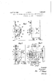
- a Fig. 1 is a side-elevation of thexfront part of a printing press v:an'dQthe rear part of a sheet vfeeding "device before they have been coupled with onezanother; v
- Fig. 3 is a plan v of the device showing the 1 means-tor fatenailyiguiding the press and I the feeding device I in regard to one another during'thecoupllingoperation.
- a Figs; 14C and :5 show a modificationo-f the 1 device for coupling the airconduits between the press and the feedingdevice, 1
- the bearing bracket 3 Provided vvith an lattachmentzi-n the form of aneyelet in which" an axle '12 is fixed on Wihieh,'oin 'Ibothsides' of "the saidbearing bracket, lugs 13 are mounted, the freev ends of WhiChLa-re shaped so as a cheiinwheel 19 mounted on the shaft 7 ,'the i to constitute ibearing members lt.
- the saidlugsJl-3 are brought into the'position -shoWn inj-'Fig.
- a stub shaft 17 is journalled, which, in the coupled position of the apparatus, is co-axial with the shaft 7 and is provided with a displaceable coupling member 18 corresponding to the coupling member 11 provided on the shaft 7.
- a transverse member 19 is also provided to which a forked guide member 21 is fixed by means of screw bolts 20, the space between the arms of the fork of the said member 21 serving for engagement with the guard 8 which is likewise constructed so as to constitute a guide member.
- the arms of the forked guide member 21 are bevelled on their inner sides at the ends and the guard 8 is similarly bevelled on its outer sides.
- the arms of the forked guide member 21 are also provided with forks located perpendicularly to the horizontal fork of the said member.
- The. pin 22 and the prolongation 23 are arranged on the framework 2 of the feeding device at such a height that, when the feeding device which is laterally guided with regard to the press on the one hand by means of the forked member 21 and on the other hand'by means of the guard 8, is brought up to the press, the said pin and prolongation engage with the bearing members 14 arranged on the lugs 13 which are in the initial position illustrated in Fig.
- the lugs 13 are turned backwards and thereby raise thefront part of the framework of the feeding device until such time as they have passed through the vertical position after which they lower the front of the yfeeding device again, the guide member 21 beingmeanwhile moved downwards over the guard and the position of the. feeding device with regard to the press being automatical- 1y adjusted laterally.
- the forks at the ends 'of the arms of the guide member 21 engage with the bearings 5, 6 of the bearing bracket 3.
- the turning movement of the lugs 13 ceases when the stops 27 provided at their upper ends come to rest on thefront of the framework 1.
- the coupling member 18 In order to carry out the coupling operation the coupling member 18 is now displaced so as to bring it into engagement with the fixed coupling member 11.
- the coupling members 11, 18 are so constructed that the coupling operation can only be efi'ected in one definite position of the'said members with regard to one another.
- the claws and recesses of the coupurpose been During the cooling operation the nozzle passes into the socket 25, asa consequence of Which the air conduit of the press is simultaneously connected with the air conduit of the feeding device during the said coupling operation.
- the lugs 13 may, of course, be arranged on the sheet feeding device instead of on the press in such manner that when the feeding device is brought upto the press they rest t will also be understood that the lateral guiding devices and the devices for coupling the air conduits may'also be similarly reversed.
- inclined guide tracks provided at the end with a stop member may also be provided.
- a coupllng member 56 1s arranged laterally on the framework 1 of the press, the, sa d coupling member having a suction conduit 28 and a pressure air conduit 29 connected; to it.
- the coupling member 56 1s provlded with a corresponding suction air conduit 30 and a pressure air conduit 31.
- a closing and throttling member 32 and 33 respectively are arranged in each of these conduits .
- the coupling sockets of the conduits 30, 31 are each provided with packing 34-.
- a coupling vmember 35 carried on a support 36 is provided, the said coupling member being provided with a suction conduit 37 and a pressure air conduit 38.
- the ends of both of .these conduits are cut off flush or are like wise provided with packing members adapted to rest flush up against the packing m-em ybers provided on the coupling member 56 51.7
- the suction conduit 37 is provided laterally with a branchkoonnectron I39 which is connected to a suction feed- "ing roller 40 by means of a pipe 41 and the pressure air conduit 38 'is provided laterally with a branchconnectison 42 for a pipe 43 which is connected to blast nozzles :arrang ed ongthe :sheet pile stops
- aligning means comprising means for automatically hftin-g the sheet feeding device upon its rear wheel's during its movement towards the stationary press, and means for guiding the sheet feeding device bothlaterally .and vertically .duringsaid movement-and the lifting movement, substantially as described.
- a stationary press a separate transportable sheet feeding device adapted to :be connected to said press to co-operate therewith and mounted on Wheelsrunning freely- :on-the ground; aaclutch member on said stationary printing press; aclutch member "on iSBjld transportable sheet feeding device; and means for bring-ingthe said two clutch members into alignment when theisheet feeding devicebas been moved :to-
- :saidmeans comprising means for guiding the said sheet feeding device both horizontally [and vertically during its movement towards the press and means for raising the said sheet feeding device about its rear wheels whilst it is vertically guided, whereby alignment of the clutch 'parttakes place in a raised position of the sheet feeding device, substantially
- a stationary printing press a transportablesheet feeding device mounted on wheels; .a clutch member on said stationary printing press; a clutchmember on said transportable sheet feeding device;
- interengaging members upon the said stationary printing press and said transport able sheet feeding device means for first automatically lifting the said sheet feeding device during its movement towards the stationary printing. press and then slightly lowering the said sheet feeding device; and means upon the stationary press for limiting the movement-of the said lifting means, substantially as described.
- a stationary printing press a transportable sheet feeding device mounted on wheels; a clutch member on said stationary printing press; a co-operating clutch member on said sheet feeding device; and means operable by the movement of the sheet feeding devicetowards'the stationary press for bringing into alignment the said two clutch members; said means comprising means for guiding the said movable sheet feeding device both horizontally and vertically during its movement towards the stationary printing press; andmeans for raising the said sheet feeding device upon its rear wheels, said raising means comprising rocking lugs pivotally mounted upon said stationary press and members upon said sheet feeding device adapted to engage said rocking lugs, said rocking lugs being at the time of the engagement slightly inclined forward, and being at the'end of the movement slightly inclined backward and supported in the latter position, and stops upon the stationary press for supporting the lugs in the latter position, substantially as described.
- a stationary printing press a transportable sheet feeding device mounted on wheels; co-operating clevices on. said stationary printing press and said transportable sheet feeding device.
- said co-operating devices comprising a driving shaft on the stationary press. a clutch member on said driving shaft, a driven shaft on the sheet feeding device, a clutch member on said driven shaft, an air supply member on the stationary press, a corresponding air receiving nozzle on the sheet feeding device; and means operable by the movement of the sheet feeding device towards the stationary press for bringing into. alignment the said co-operating devices, said aligning means comprising means for automatically lifting the sheet feeding device upon its rear wheels during its movement towards the stationary press, and means for guiding the sheet feeding device both laterally and vertically during said movement, substantially as described.
- a stationary printing press a transportable sheet feeding device mounted on wheels; co-operating devices on said stationary'printing press and said transportable sheet feeding device comprising: a driving shaft upon said printing press, a clutch member on said driving shaft, a driven shaft upon said sheet feeding device, a clutch member on said driven shaft, an air suction port on said press, an air discharge port on said press, a packing ring in said air suction port, a packing ring in said air discharge port, a corresponding air suction port on the sheet feeding device, a correspond-ing air discharge port on said sheet feeding device, manually operable means for controlling the passage of the air through the air suction port on the press, manually operable means for controlling the passage of the air through the air discharge port on the press, mechanically operatedvalve means for controlling the passage of the air from the air discharge port upon the sheet feeding device and mechanically operated valve means for controlling the escape of the air from the air suction port on the sheet feeding device; and aligning means operable by the movement of the sheet feeding device towards the stationary press
- a stationary printing press a transportable sheet feeding device mounted on wheels; co-operating devices on said stationary printing press and said transportable sheet feeding device comprising: a
- said airports havingend faces adapted toflbea correspond stantially as described.
- said aligning means como prising means for automatically lifting the sheet feeding device upon its rear wheels during its movement towards the, stationary press, and means for guiding the sheet feeding device both horizontally and vertically during said movement and the lifting movement, substantially as-described.
- a stationary printing press a separate transportable sheet feeding printing press being-located at a slightly device adapted to be connected to said press c to co-operate'therewith and mounted on front and on rear wheels running freely on the ground; co-operating devices on said stationary printing press sheet feeding device, the devices on the stationary printingpress being located at a higher level than the corresponding devices upon and said transportable V the transportable sheet feeding device; and
- aligning means operable by the movement of the sheet feeding device towards the stationary press for bringing into alignment the said co-operating devices, said aligning means comprising means forautomatically lifting the sheet feeding device upon its rear wheels during its movement towards the stationary press, means upon the stationary printing press for supporting the lifted porfor guiding the sheet feeding device both tion of the sheet feeding device, and means horizontally and vertically during, said movement and the lifting movement, sub- Signed at Leipzig, Germany, this eleventh GEORG sPIEss.
Landscapes
- Engineering & Computer Science (AREA)
- Mechanical Engineering (AREA)
- Sheets, Magazines, And Separation Thereof (AREA)
Description
G. SPIESS April 12, 1932.
DEVICE FOR COUPLING A PRINTING PRESS WITH A SHEET FEEDING'DEVICE Filed Nov. 22, 1950 2 Sheets-Sheet In venfor: eorg'J bl'qfi. /i%a flffor ney G. SPIESS 1,853,941
DEVICE FOR COUPLING A PRINTING PRESS WITH A SHEET FEEDING DEVICE April 12, 1932.
Filed NOV, 22. 1930 2 Sheets-Sheet 2 Fig. 5.
In van/or: G'eoy/uze lW/arwey Patented Apr. 12, 1932 -UlNHTET STATES mm T d fenone srinss, or LEII'ZYIQIGEEQMANY V DEVICE non oonrnmenrnmrme rnnss wr'rn VA 'saEET -Fas1:11w EVICE Application Inca November 22, 1930,'Ser'ia1No 49?;504,'-am1 ineerin y' m 5, 1 a
"The present invention relates to a device for use with printing presses for coupling a press and its drive a transportable sheet feeding device by means of coupling members which are arranged on 'the press and on the feeding vice :and engage with one another during thecoupl-ing'operation. v
"The principal object ofthe inventlon 1s to provide means whereby, when the feeding dey vice is bronght to the pressfihe coupling members Which are adapte'cl to engage with one a noth'er automaticallyguide and adjust the sheet feeding device and raise the latter by turning it around its rear Wheels into such a position that the coupling members for the drive of the pressand the feeding device are located opposite to one another in the position of readiness for effecting the coupling operation. For this purpose swinging lugs or i arms carrying bearing members are arranged g Re'fer "g toTF-"gures numeral denotes the framework of a printing ipness, ofnvhich only t he fronti'part is' "shown, ian'd the reference numeral 2 denotes on the press, which lugs guide-the ooup1ing members of the feeding device and raiseit into the coupling positiom the said lugs resting the coupling position against-stops provided in the framework of' the press. In
addition to this, air supplynozzles and electrical contacts adapted to engage with one anotheri'n the coupled position ofthedev-i c'e are provided on the press and on the feeding device, so that when the feeding device and the press are brought together the Various conduits and electrical connections of the feeding; device and of the press are automatically connected 'v'v-ith-one another. By 'means; of
the invention'the resultis attained that by inerel yfbringing the feeding device up to the press the drivinggear; the supply conduits "and the electrical connections of the feeding device and the press are coupled with one 0 another in-readiness for working operations and that likewise by inerdly'moving the feeding'device away from the press again the driving gear, the conduits and the connections are uncoupled :t:('om oneanother.
"Twoconstructional-forms of the device according to the invention are illustrated by Way e f-example in the accompanying (new ings in which thepress and the feeding device have been shown broken off, and all details-of the apparatus which are unnecessary for the comprehension "been :omitted.
0f the invention-have the drawings; Fi s; L3 illustrate the I one constructional form. a Fig. 1 is a side-elevation of thexfront part of a printing press v:an'dQthe rear part of a sheet vfeeding "device before they have been coupled with onezanother; v
2 :is'a similar elevation lOIf thejpress and of the feeding device in the -coupled position, and
' t Fig. 3 is a plan v of the device showing the 1 means-tor fatenailyiguiding the press and I the feeding device I in regard to one another during'thecoupllingoperation. a Figs; 14C and :5 show a modificationo-f the 1 device for coupling the airconduits between the press and the feedingdevice, 1
",Fignbeing an'aelevati'omiand l Fig. 5 a plan of the device;
r1, :2, *3; the :reference the framework ofaitransp orta ble sheet feed- ?irrg'devi'ce. G11 the front tofithe framework def the press a [bearing bracket 3 is fixed by means :of screws, whichtbeazring bracket is I provided 'ivzith two bearings 55,1 56 in which a a shaft 7 is j'ourna11edf. The bearing bracket 7 is so constructed that the 'paTtdOcated-between the bearings F5; 6"forms a:g1uardfi8 for "1 1 is rigidly fixed.
The bearing bracket 3 {provided vvith an lattachmentzi-n the form of aneyelet in which" an axle '12 is fixed on Wihieh,'oin 'Ibothsides' of "the saidbearing bracket, lugs 13 are mounted, the freev ends of WhiChLa-re shaped so as a cheiinwheel 19 mounted on the shaft 7 ,'the i to constitute ibearing members lt. Previous to the operation of couplin gthe feeding device with the press, the saidlugsJl-3 are brought into the'position -shoWn inj-'Fig. 1, in which they are held firmly inposi'ti'on by means of a stop 1 5resting against the bearing bracket 'In the-1 framework 2 o fthe feedingdevicetwh-ich is -mountedron rollers 16 so as to be transportable, a stub shaft 17 is journalled, which, in the coupled position of the apparatus, is co-axial with the shaft 7 and is provided with a displaceable coupling member 18 corresponding to the coupling member 11 provided on the shaft 7. In the framework of the feeding device a transverse member 19 is also provided to which a forked guide member 21 is fixed by means of screw bolts 20, the space between the arms of the fork of the said member 21 serving for engagement with the guard 8 which is likewise constructed so as to constitute a guide member. For this purpose the arms of the forked guide member 21 are bevelled on their inner sides at the ends and the guard 8 is similarly bevelled on its outer sides. The arms of the forked guide member 21 are also provided with forks located perpendicularly to the horizontal fork of the said member. During the coupling operation the bearings 5, 6 provided on the bearing bracket 3 fixed to the framework of the press engages with the forks provided on the aforesaid arms.
which is furnished with a prolongation 23 [likewise .adapted to co-operate with one of the bearing members 14:. The. pin 22 and the prolongation 23 are arranged on the framework 2 of the feeding device at such a height that, when the feeding device which is laterally guided with regard to the press on the one hand by means of the forked member 21 and on the other hand'by means of the guard 8, is brought up to the press, the said pin and prolongation engage with the bearing members 14 arranged on the lugs 13 which are in the initial position illustrated in Fig.
1. When the feeding device is brought up to the press the lugs 13 are turned backwards and thereby raise thefront part of the framework of the feeding device until such time as they have passed through the vertical position after which they lower the front of the yfeeding device again, the guide member 21 beingmeanwhile moved downwards over the guard and the position of the. feeding device with regard to the press being automatical- 1y adjusted laterally. At the same time the forks at the ends 'of the arms of the guide member 21 engage with the bearings 5, 6 of the bearing bracket 3. The turning movement of the lugs 13 ceases when the stops 27 provided at their upper ends come to rest on thefront of the framework 1. In this position the pin 22 and the shaft 17 of the feeding device are located co-aXially with the .shaft 7 of the press and the coupling mem- 1 bers 11, 18 arelocated opposite to one another in the position requisite for efiecting; the couon the framework of the latter.
pling operation. In order to carry out the coupling operation the coupling member 18 is now displaced so as to bring it into engagement with the fixed coupling member 11. In order to ensure that the apparatus should be in the correct relative positions for effecting the coupling, i. e. that the devices appertaining to the pressand' the platen should be in the necessary relative positions for the working operations, the coupling members 11, 18 are so constructed that the coupling operation can only be efi'ected in one definite position of the'said members with regard to one another. In the constructional example illustrated the claws and recesses of the coupurpose, been During the cooling operation the nozzle passes into the socket 25, asa consequence of Which the air conduit of the press is simultaneously connected with the air conduit of the feeding device during the said coupling operation.
In similar manner can be established between the feeding device and the press automatically by means of suitable contacts. I
The lugs 13 may, of course, be arranged on the sheet feeding device instead of on the press in such manner that when the feeding device is brought upto the press they rest t will also be understood that the lateral guiding devices and the devices for coupling the air conduits may'also be similarly reversed.
Instead of the lugs 13, inclined guide tracks provided at the end with a stop member may also be provided.
In the modification shown in Figs. 4 and 5, a coupllng member 56 1s arranged laterally on the framework 1 of the press, the, sa d coupling member having a suction conduit 28 and a pressure air conduit 29 connected; to it. The coupling member 56 1s provlded with a corresponding suction air conduit 30 and a pressure air conduit 31. In each of these conduits a closing and throttling member 32 and 33 respectively are arranged. The coupling sockets of the conduits 30, 31 are each provided with packing 34-. On the framework of the sheet feeding device a coupling vmember 35 carried on a support 36 is provided, the said coupling member being provided with a suction conduit 37 and a pressure air conduit 38. The ends of both of .these conduits are cut off flush or are like wise provided with packing members adapted to rest flush up against the packing m-em ybers provided on the coupling member 56 51.7
electrical connection when the feeding device is brought up into the coupling position. The suction conduit 37 is provided laterally witha branchkoonnectron I39 which is connected to a suction feed- "ing roller 40 by means of a pipe 41 and the pressure air conduit 38 'is provided laterally with a branchconnectison 42 for a pipe 43 which is connected to blast nozzles :arrang ed ongthe :sheet pile stops The suction conduit '3( is' fu'rther provided with an opening leading into the open air,
which can be opened or closed bymeans of a flap 45 for the purpose of ;tio.n"in and out of action. The flapi i ia-is 7 press; a separate transportable sheet feed .ing device which can be' conne'otedtosaid mounted on the one arm of a bell crank lever which is spring controlled and is pivoted j at $6.,the other arm of said bell crank lever 4:? being provided with a roller 18 and being :c'am disc by means i I :claim;
of a spring. r com binati-onfr a stationaryiprinting press to co-operate therewith and, which is mounted on .wheels running freely on the ground; a driving shaft upon said-printing press; asdri-ven shaft upon said sheet feeding device; a clutch for coupling said driving shaft to .s aid driven shaft; comprising a clutch portion on one shaft and a clutch portion on I the other shaft; means for automatically lift- :ing the said 'sheetfeeding device during its movement towards the stationary press; means for guiding the sheet feeding device horizontally relatively to the stationary press,
and means for guiding the sheet feeding device vertically relatively to the stationary press during the lifting ope-ration, whereby the sheet feeding device is registered both horizontally and vertically relatively to the stationary pressand the clutch members are brought into alignment, substantially as described.
2.- The combination "of a stationary printing press a'separate transportable sheet feed ing device which can be rconnected' to said press to co-operate therewith and which is mounted on wheels running freely on the ground; co-opera-ting devices on said stationary: printing :press and saidtranspontab-le sheet feeding device; and means operable by the movement of the sheet feeding device towards the stationary press for bringing into alignment the said co-operating devices, said putting the sucas described.
aligning means comprising means for automatically hftin-g the sheet feeding device upon its rear wheel's during its movement towards the stationary press, and means for guiding the sheet feeding device bothlaterally .and vertically .duringsaid movement-and the lifting movement, substantially as described. i
3. In combination: a stationary printing press; a transportable sheet feeding devicemounted .on wheels; means for zgluiding said 7 sheet feeding device both laterally and we, tically relatively :to the said stationary print- ,ingpress during its-movement towards the press; andmeans for lifting'theksheet feeding device during a part'of its movement towards the stationary printing press and 1" slightly lowering the said sheet feeding =deand for the purpose describe-d.
vice at the end of its movement towards the j stationary printing press, substantially as? 4. In combination; a stationary press; a separate transportable sheet feeding device adapted to :be connected to said press to co-operate therewith and mounted on Wheelsrunning freely- :on-the ground; aaclutch member on said stationary printing press; aclutch member "on iSBjld transportable sheet feeding device; and means for bring-ingthe said two clutch members into alignment when theisheet feeding devicebas been moved :to-
wards the stationary printing press, :saidmeans comprising means for guiding the said sheet feeding device both horizontally [and vertically during its movement towards the press and means for raising the said sheet feeding device about its rear wheels whilst it is vertically guided, whereby alignment of the clutch 'parttakes place in a raised position of the sheet feeding device, substantially In combination: a stationary printing press; a transportablesheet feeding device mounted on wheels; .a clutch member on said stationary printing press; a clutchmember on said transportable sheet feeding device;
V and means 'forbringing-into alignment the said :two clutch members during'the move, ment of the said transportable "sheet feeding device to'vvards the stationary press,:said ahgnmg means comprlsing n combination:
'a'ry printing v press members upon the translugs pivot-ally mounted upon tlresai'dstation 'porta'ble'sheet feeding device adapted tomboy I gripped by said lugs, said :lugsbeing so a rranged that they swing" upwards during the movement of the sheet feeding device; and means for horizontally and vertically guidsheet feeding device and a member upon the stationary press, engaged by said horizontal and vertical fork memberasubstantially as described. v V v ing the sheet feeding device relatively "to the stationary press; said means comprising hori- "zontal a-nd' vertioail" fork ,rnembers upon the.
ing interengaging members upon the said stationary printing press and said transport able sheet feeding device; means for first automatically lifting the said sheet feeding device during its movement towards the stationary printing. press and then slightly lowering the said sheet feeding device; and means upon the stationary press for limiting the movement-of the said lifting means, substantially as described.
7 In combination: a stationary printing press; a transportable sheet feeding device mounted on wheels; a clutch member on said stationary printing press; a co-operating clutch member on said sheet feeding device; and means operable by the movement of the sheet feeding devicetowards'the stationary press for bringing into alignment the said two clutch members; said means comprising means for guiding the said movable sheet feeding device both horizontally and vertically during its movement towards the stationary printing press; andmeans for raising the said sheet feeding device upon its rear wheels, said raising means comprising rocking lugs pivotally mounted upon said stationary press and members upon said sheet feeding device adapted to engage said rocking lugs, said rocking lugs being at the time of the engagement slightly inclined forward, and being at the'end of the movement slightly inclined backward and supported in the latter position, and stops upon the stationary press for supporting the lugs in the latter position, substantially as described.
, 8. The combination of: a stationary printing press; a transportable sheet feeding device mounted on wheels; co-operating clevices on. said stationary printing press and said transportable sheet feeding device. said co-operating devices comprising a driving shaft on the stationary press. a clutch member on said driving shaft, a driven shaft on the sheet feeding device, a clutch member on said driven shaft, an air supply member on the stationary press, a corresponding air receiving nozzle on the sheet feeding device; and means operable by the movement of the sheet feeding device towards the stationary press for bringing into. alignment the said co-operating devices, said aligning means comprising means for automatically lifting the sheet feeding device upon its rear wheels during its movement towards the stationary press, and means for guiding the sheet feeding device both laterally and vertically during said movement, substantially as described.
9. The-combination of: astationary printing press; a transportable sheet feeding device mounted on wheels; co-operating devices on said stationary printing press and said transportable sheet feeding device comprising a driving shaft upon said printing press, a clutch member upon said driving shaft, a driven shaft upon said sheet feeding device, a clutch member on said driven shaft, contact connectionmeans for connecting corresponding suction and pressure passages provided on the stationary press and on the transportable sheet feeding device; and means operable by the movement of the sheet feeding device towards the stationary press for bringing into alignment the said co-operating devices, said aligning means comprising means for automatically lifting the sheet feeding device upon its rear wheels during its movement towards the stationary press, and means for guiding the sheet feeding device both laterally and vertically during said movement, substantially as described.
10. In combination: a stationary printing press; a transportable sheet feeding device mounted on wheels; co-operating devices on said stationary'printing press and said transportable sheet feeding device comprising: a driving shaft upon said printing press, a clutch member on said driving shaft, a driven shaft upon said sheet feeding device, a clutch member on said driven shaft, an air suction port on said press, an air discharge port on said press, a packing ring in said air suction port, a packing ring in said air discharge port, a corresponding air suction port on the sheet feeding device, a correspond-ing air discharge port on said sheet feeding device, manually operable means for controlling the passage of the air through the air suction port on the press, manually operable means for controlling the passage of the air through the air discharge port on the press, mechanically operatedvalve means for controlling the passage of the air from the air discharge port upon the sheet feeding device and mechanically operated valve means for controlling the escape of the air from the air suction port on the sheet feeding device; and aligning means operable by the movement of the sheet feeding device towards the stationary press for bringing into alignment the said co-operating devices, said aligning means comprising means for automatically lifting the sheet feeding device upon its rear wheels during its movement towards the stationary press, and means for guiding the sheet feeding device both horizontally and vertically during said movement, substantially as described.
11. In combination: a stationary printing press; a transportable sheet feeding device mounted on wheels; co-operating devices on said stationary printing press and said transportable sheet feeding device comprising: a
driving shaft upon said printing press, a
clutch member upon said driving shaft, a
driven shaft upon said sheet'feeding device, a clutch member on said driven shaft, an air port on said printing press,
ing air port on said sheet feeding device, said airports havingend faces adapted toflbea correspond stantially as described.
day of November, 1930 brought into contact, packing means for producing a tight joint between the said end faces by the mere contact of said end faces i and aligning means operable. by the movement of the sheet feeding device towards the stationary press for bringing into align- ,ment' the said (Jo-operating dev1ces,'sa1d aligning means comprislng means for auto to co-operate therewith and mounted on' front and rear wheels running freely on the ground, the rear wheels being vertically adjustable; co-operating devices on said sta-' .tionary printing press andsaid transportable sheet feeding device, the devices on the higher level than the co-operating devices on the transportable sheet feeding device; and means operable by the movement of the sheet feeding device towards the stationary. press for bringing into alignment the said cooperating devices, said aligning means como prising means for automatically lifting the sheet feeding device upon its rear wheels during its movement towards the, stationary press, and means for guiding the sheet feeding device both horizontally and vertically during said movement and the lifting movement, substantially as-described.
13. In combination: a stationary printing press; a separate transportable sheet feeding printing press being-located at a slightly device adapted to be connected to said press c to co-operate'therewith and mounted on front and on rear wheels running freely on the ground; co-operating devices on said stationary printing press sheet feeding device, the devices on the stationary printingpress being located at a higher level than the corresponding devices upon and said transportable V the transportable sheet feeding device; and
aligning means operable by the movement of the sheet feeding device towards the stationary press for bringing into alignment the said co-operating devices, said aligning means comprising means forautomatically lifting the sheet feeding device upon its rear wheels during its movement towards the stationary press, means upon the stationary printing press for supporting the lifted porfor guiding the sheet feeding device both tion of the sheet feeding device, and means horizontally and vertically during, said movement and the lifting movement, sub- Signed at Leipzig, Germany, this eleventh GEORG sPIEss.
Ian
Applications Claiming Priority (1)
| Application Number | Priority Date | Filing Date | Title |
|---|---|---|---|
| DE1853941X | 1928-05-05 |
Publications (1)
| Publication Number | Publication Date |
|---|---|
| US1853941A true US1853941A (en) | 1932-04-12 |
Family
ID=7746125
Family Applications (1)
| Application Number | Title | Priority Date | Filing Date |
|---|---|---|---|
| US497504A Expired - Lifetime US1853941A (en) | 1928-05-05 | 1930-11-22 | Device for coupling alpha printing press with alpha sheet feeding device |
Country Status (1)
| Country | Link |
|---|---|
| US (1) | US1853941A (en) |
-
1930
- 1930-11-22 US US497504A patent/US1853941A/en not_active Expired - Lifetime
Similar Documents
| Publication | Publication Date | Title |
|---|---|---|
| US1853941A (en) | Device for coupling alpha printing press with alpha sheet feeding device | |
| JPS60122658A (en) | Device for distributing and feeding sheets to business machine | |
| US3542241A (en) | Vacuum feeding apparatus | |
| US2626147A (en) | Jogging device for piled sheets | |
| JPH06219605A (en) | Device for alinging side of sheet paper in press | |
| GB1064302A (en) | Sheet delivery mechanism | |
| US2901250A (en) | Automatic sheet stacker apparatus | |
| US2434411A (en) | Selective transfer apparatus for plywood | |
| CN113635663B (en) | Circuit board printing fixing device | |
| CN205802617U (en) | A kind of finance voucher folding machine | |
| CN209097113U (en) | A kind of Curved screen pad pasting transport mechanism | |
| CN214827493U (en) | Full-automatic paper feeding device of corrugated board printing machine | |
| CN205467322U (en) | Full -automatic rubber roll flatulence machine of impressing | |
| US2230633A (en) | Sheet feeder | |
| CN105329658A (en) | Automatic paper supporting device | |
| CN109230397B (en) | Unpowered automatic positioning mechanism | |
| CN218682263U (en) | Full-automatic mask feeding and edge covering device | |
| US2240423A (en) | Sheet feeding control device | |
| US2159456A (en) | Automatic sheet feeding device | |
| CN208665682U (en) | Automatic sealing device | |
| CN221438739U (en) | Paper drawer for printing machine with hold-down mechanism | |
| CN215620967U (en) | Automatic card device of plugging into and production line thereof | |
| GB1252681A (en) | ||
| US2156218A (en) | Billet handling device for tube mills | |
| US2984481A (en) | Suction-head document feeder |