US1853833A - Wheeled toy - Google Patents
Wheeled toy Download PDFInfo
- Publication number
- US1853833A US1853833A US541453A US54145331A US1853833A US 1853833 A US1853833 A US 1853833A US 541453 A US541453 A US 541453A US 54145331 A US54145331 A US 54145331A US 1853833 A US1853833 A US 1853833A
- Authority
- US
- United States
- Prior art keywords
- recesses
- frame
- axles
- spring member
- aligned
- Prior art date
- Legal status (The legal status is an assumption and is not a legal conclusion. Google has not performed a legal analysis and makes no representation as to the accuracy of the status listed.)
- Expired - Lifetime
Links
Images
Classifications
-
- A—HUMAN NECESSITIES
- A63—SPORTS; GAMES; AMUSEMENTS
- A63H—TOYS, e.g. TOPS, DOLLS, HOOPS OR BUILDING BLOCKS
- A63H17/00—Toy vehicles, e.g. with self-drive; ; Cranes, winches or the like; Accessories therefor
- A63H17/26—Details; Accessories
- A63H17/262—Chassis; Wheel mountings; Wheels; Axles; Suspensions; Fitting body portions to chassis
Definitions
- the toy frame is provided with aligned downwardly opened recesses adapted to receive the axle of a preferably integral wheel and axle unit and a spring member is provided which is adapted to be sprung into engagement with seating means with a portion underlying the axle to hold it in the recesses.
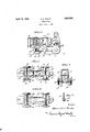
- Figure 1 is a side elevation partly in section and with parts broken away of'a toy embodying the invention in one form;
- Fi ure 2 is a bottom plan view of the toy b I v shown in Flgure 1;
- Figure 3 is a section on line 33 of- Figure Figure 4 is a bottom plan view of a toy embodying the invention-in slightly modified form; and H Figure 5 is a section on line 5-5 of Figure 4.
- a frame generally indicated at 10, is provided and, as here shown, is in simulation of a tractor. As particularly indicated in Figure 3, the frame 1931. Serial No. 541,453.
- the lower side wall portions of the frame are provided with outwardly extended boss-like portions'l l, 15, 16, and 17 provided with aligned downwardly openedrecesses 14, 15, and 16, 17 in which are seated axles 18 and 19 which are provided respectively with wheels 20, 21formed integral therewlth.
- the wall portions of the frame are provided at their lower edges with opposed inwardly extending lugs 22, 23, and 24, 25, and intermediate these two sets of lugs and. somewhat thereabove with opposed lugs 26 and 27.
- An elongated laterally compressible bent spring member 28 shown in Figures'l, 2 and 3 as being substantially hairpin-shaped is adapted to be engaged with the side wall portions of the frame immediately above lugs 22 to 25 and below lugs 26 and 27 with its end portions underlying axles 18 and 19 to hold the latter in'theirs'eats.
- member 28 is laterally compressed so as to be passed substantially broad side between the opposed lower lugs whereupon it is permitted to expand into contact with the lower wall portions, its downward displacement being prevented by the lower lugsand its upward displacement by the upper lugs 26 and 27 as well as by. the axles 18 and 19.
- Frame portions 11 and 12 are provided with complementary end wall portions 29,
- the described arrangement permits rapid assembly of the frame and axles and alfords positive means for retaining the axles in the downwardly open frame recesses.
- the lower wallportions 33 and 34: of the frame are pro- EDWARD s. PEAKE, or WESTERVILLE, OHIO, ASSIGNOR To THE KILGORE MFG. 00M
- a laterally compressible spring member 35 is adapted to be engaged with its ends'underlying the axles to retain the latter in the frame recesses.
- the spring member 35 as here shown, is in the form of an elongated spring loop whose longitudinal displacement is prevented by end wall portions of the frame asdescribed above in connection with Figures 1 to 3.
- means otherthan the axles are provided for preventing upward displacement of the spring member, the spring seating means being such as to retain the ends of the'spring member slightly out of contact with the axles so as not to impede the rotation'of the latter" by frictional engagement therewith.
- a frame having side wall portions provided with aligned downwardly open recesses, an axleseated in said recesses, and a bent spring member engaged in seating means presented by the side walls and having a portion underlying the axle to hold the latter in said recesses.
- a frame having side wall portions provided with pairs of aligned downwardly open recesses, axles seated in the aligned recesses, inwardly projecting lugs on said side walls adjacent said recesses, and an elongated laterally compressible spring member laterally engaged with said side walls above said lugs with its end portions underlying the axles to hold the latter in said recesses.
- a frame havin side wall portions provided with pairs of aligned downwardly open recesses, axles seated in the aligned recesses, inwardly projecting lugs on said side walls adjacent said recesses, an elongated laterally compressible spring member laterally engaged with said side walls above said lugs with its end portions underlying the axles to hold the latter in said recesses, and inwardly projecting lugs 011 the side walls between the first mentioned lugs and engaged above said spring member.
- a frame having side wall portions provided with pairs of aligned downwardly open recesses, axles seated in the aligned recesses, the side walls being provided with inwardly faced longitudinally extending grooves, and an elongated laterally compressible spring member laterally engaged in said grooves with its end portions underlying the axles to hold the latter in said recesses.
- a frame having side wall portions provided with pairs of aligned downwardly open recesses, axles seated in the aligned recesses, and a hairpin shaped spring member engaged in seating means presented by the side walls with its end portions underlying the axle to hold the latter in said recesses.
- a frame having side wall portions provided with pairs of aligned downwardly open recesses, axles seated in the aligned recesses, and an elongated spring loop engaged in seating means presented by the side walls withjits end portions underlying the axle to hold the latter in said recesses.
- a frame having side wall portions provided with pairs of aligned downwardly open recesses, axles seated in aligned recesses, and an elongated laterally compressible spring member laterally engaged in seating means presented by said side walls with its end portions underlying the axles to hold the latter in said recesses, said frame also includedin means at the ends of said spring member for limiting relative longitudinal movement of the latter.
- a frame having side wall portions provided with pairs of aligned downwardly open recesses, axles seated in aligned recesses, and an elongated laterally compressible spring member laterally engaged in seating means presented by said side walls with its end portions underlying the axles to hold the latter in said recesses, said frame also including end wall portions joining the side wall portions and. extending below the ends of said spring member for limiting relative longitudinal movement of the latter.
- a frame including opposed wall portions and having downwardly open aligned recesses, an axle in said recesses, and means for retaining the axle in said retesses comprising a compressible member sprung into engagement with seating means presented by the opposed walls and having a portion underlying the axle.
- a frame presenting 1 aligned downwardly open recesses, an axle seated in said recesses, and an elongated flat spring member engaged with seating means on the frame and extending beneath the axle to hold it in the recesses, the frame presenting means beyond the ends of said spring member to limit longitudinal movement of the latter in both directions.
Landscapes
- Toys (AREA)
Description
A ril 12, 1932. g. s PEAKE 1,853,833
WHEELED TOY Filed June 1, 1931 toys.
" the wheels in place.
Patented Apr. 12, 1932 UNITE STATES PATENT OFFICE .PANY, OF WESTERVILLE, OHIO, A CORPORATION OF OHIO WHEELED TOY Application filed June 1,
Heretofore, it has been the general practioe either to construct the frame of such toys in two parts which are provided with axle openings, the frame portions being brought together with the axle ends'in such openings and then riveted together; or to pass the axles through aligned openings provided in the frame, place wheels on the axle ends, and upset the axle extremities to hold Both of these procedures require a disproportionate amount of time where the article must be cheaply produced and it is the principal purpose of the present invention to provide means whereby the time required for assembling may be reduced to a minimum.
According to the present invention, the toy frame is provided with aligned downwardly opened recesses adapted to receive the axle of a preferably integral wheel and axle unit and a spring member is provided which is adapted to be sprung into engagement with seating means with a portion underlying the axle to hold it in the recesses.
While the invention is susceptible of various embodiments, I have shown two practical and preferred embodiments in the ac companying drawings by way of illustration. In the drawings, 1 V
Figure 1 is a side elevation partly in section and with parts broken away of'a toy embodying the invention in one form;
Fi ure 2 is a bottom plan view of the toy b I v shown in Flgure 1;
40 Figure 3 is a section on line 33 of- Figure Figure 4 is a bottom plan view of a toy embodying the invention-in slightly modified form; and H Figure 5 is a section on line 5-5 of Figure 4.
Referring to the drawings, a frame, generally indicated at 10, is provided and, as here shown, is in simulation of a tractor. As particularly indicated in Figure 3, the frame 1931. Serial No. 541,453.
may be conveniently made of right and left hand complementary portions lland 12 secured together by means of a rivet 13. The lower side wall portions of the frame are provided with outwardly extended boss-like portions'l l, 15, 16, and 17 provided with aligned downwardly openedrecesses 14, 15, and 16, 17 in which are seated axles 18 and 19 which are provided respectively with wheels 20, 21formed integral therewlth. As shown in Figures 1, 2 and 3 the wall portions of the frame are provided at their lower edges with opposed inwardly extending lugs 22, 23, and 24, 25, and intermediate these two sets of lugs and. somewhat thereabove with opposed lugs 26 and 27. An elongated laterally compressible bent spring member 28 shown in Figures'l, 2 and 3 as being substantially hairpin-shaped is adapted to be engaged with the side wall portions of the frame immediately above lugs 22 to 25 and below lugs 26 and 27 with its end portions underlying axles 18 and 19 to hold the latter in'theirs'eats. In assembling, member 28 is laterally compressed so as to be passed substantially broad side between the opposed lower lugs whereupon it is permitted to expand into contact with the lower wall portions, its downward displacement being prevented by the lower lugsand its upward displacement by the upper lugs 26 and 27 as well as by. the axles 18 and 19. V
30, and 31, 32 which project somewhat below member 28, as particularly shown in Figures 1 and 3, these end wall portions serving to limit longitudinal displacement of the spring member and also serving to conceal the ends of the spring member.
The described arrangement permits rapid assembly of the frame and axles and alfords positive means for retaining the axles in the downwardly open frame recesses.
-According to Figures 4 and 5, the lower wallportions 33 and 34: of the frame are pro- EDWARD s. PEAKE, or WESTERVILLE, OHIO, ASSIGNOR To THE KILGORE MFG. 00M
videdjwith longitudinally extending grooves 33, 3 1 immediately below the axles in which a laterally compressible spring member 35 is adapted to be engaged with its ends'underlying the axles to retain the latter in the frame recesses. The spring member 35, as here shown, is in the form of an elongated spring loop whose longitudinal displacement is prevented by end wall portions of the frame asdescribed above in connection with Figures 1 to 3.
Preferably, as shown in both embodiments, means otherthan the axles are provided for preventing upward displacement of the spring member, the spring seating means being such as to retain the ends of the'spring member slightly out of contact with the axles so as not to impede the rotation'of the latter" by frictional engagement therewith.
I have shown two forms of spring members and two forms of seating means therefor. Either form of spring member may, of course, be used with either form of seating means.
It will be obvious that the invention is susceptible of other embodiments than those shown and described, and consequently, I do not limit myself to structure except as in the following claims.
I claim:
1. In a wheeled toy, a frame having side wall portions provided with aligned downwardly open recesses, an axleseated in said recesses, and a bent spring member engaged in seating means presented by the side walls and having a portion underlying the axle to hold the latter in said recesses.
2. In a wheeled toy, a frame having side wall portions provided with pairs of aligned downwardly open recesses, axles seated in the aligned recesses, inwardly projecting lugs on said side walls adjacent said recesses, and an elongated laterally compressible spring member laterally engaged with said side walls above said lugs with its end portions underlying the axles to hold the latter in said recesses.
3. In a wheeled toy, a frame havin side wall portions provided with pairs of aligned downwardly open recesses, axles seated in the aligned recesses, inwardly projecting lugs on said side walls adjacent said recesses, an elongated laterally compressible spring member laterally engaged with said side walls above said lugs with its end portions underlying the axles to hold the latter in said recesses, and inwardly projecting lugs 011 the side walls between the first mentioned lugs and engaged above said spring member.
4. In a wheeled toy, a frame having side wall portions provided with pairs of aligned downwardly open recesses, axles seated in the aligned recesses, the side walls being provided with inwardly faced longitudinally extending grooves, and an elongated laterally compressible spring member laterally engaged in said grooves with its end portions underlying the axles to hold the latter in said recesses.
5. In a wheeled toy, a frame having side wall portions provided with pairs of aligned downwardly open recesses, axles seated in the aligned recesses, and a hairpin shaped spring member engaged in seating means presented by the side walls with its end portions underlying the axle to hold the latter in said recesses.
6. In a wheeled toy, a frame having side wall portions provided with pairs of aligned downwardly open recesses, axles seated in the aligned recesses, and an elongated spring loop engaged in seating means presented by the side walls withjits end portions underlying the axle to hold the latter in said recesses.
7. In a wheeled toy, a frame having side wall portions provided with pairs of aligned downwardly open recesses, axles seated in aligned recesses, and an elongated laterally compressible spring member laterally engaged in seating means presented by said side walls with its end portions underlying the axles to hold the latter in said recesses, said frame also includin means at the ends of said spring member for limiting relative longitudinal movement of the latter.
8. In a wheeled toy, a frame having side wall portions provided with pairs of aligned downwardly open recesses, axles seated in aligned recesses, and an elongated laterally compressible spring member laterally engaged in seating means presented by said side walls with its end portions underlying the axles to hold the latter in said recesses, said frame also including end wall portions joining the side wall portions and. extending below the ends of said spring member for limiting relative longitudinal movement of the latter.
9. In a wheeled toy, a frame including opposed wall portions and having downwardly open aligned recesses, an axle in said recesses, and means for retaining the axle in said retesses comprising a compressible member sprung into engagement with seating means presented by the opposed walls and having a portion underlying the axle.
10. In a wheeled toy, a frame presenting 1 aligned downwardly open recesses, an axle seated in said recesses, and an elongated flat spring member engaged with seating means on the frame and extending beneath the axle to hold it in the recesses, the frame presenting means beyond the ends of said spring member to limit longitudinal movement of the latter in both directions.
In testimony whereof I have hereunto set my hand.
EDWARD S. PEAKE.
Priority Applications (1)
| Application Number | Priority Date | Filing Date | Title |
|---|---|---|---|
| US541453A US1853833A (en) | 1931-06-01 | 1931-06-01 | Wheeled toy |
Applications Claiming Priority (1)
| Application Number | Priority Date | Filing Date | Title |
|---|---|---|---|
| US541453A US1853833A (en) | 1931-06-01 | 1931-06-01 | Wheeled toy |
Publications (1)
| Publication Number | Publication Date |
|---|---|
| US1853833A true US1853833A (en) | 1932-04-12 |
Family
ID=24159660
Family Applications (1)
| Application Number | Title | Priority Date | Filing Date |
|---|---|---|---|
| US541453A Expired - Lifetime US1853833A (en) | 1931-06-01 | 1931-06-01 | Wheeled toy |
Country Status (1)
| Country | Link |
|---|---|
| US (1) | US1853833A (en) |
Cited By (6)
| Publication number | Priority date | Publication date | Assignee | Title |
|---|---|---|---|---|
| US2552824A (en) * | 1946-11-18 | 1951-05-15 | Auburn Rubber Corp | Wheeled toy |
| US2601908A (en) * | 1946-04-16 | 1952-07-01 | Ullmann Philipp | Motor for toys |
| US3238666A (en) * | 1963-02-28 | 1966-03-08 | Hubley Mfg Company | Wheel mounting for toy vehicles |
| US4416083A (en) * | 1980-12-03 | 1983-11-22 | Custom Concepts, Incorporated | Moldable toy vehicle |
| US5120254A (en) * | 1991-02-07 | 1992-06-09 | Matchbox Toys (Usa) Ltd. | Wire suspension for toy car |
| US20240108995A1 (en) * | 2022-10-03 | 2024-04-04 | Kiding Ltd. | Toy wheel assembly |
-
1931
- 1931-06-01 US US541453A patent/US1853833A/en not_active Expired - Lifetime
Cited By (6)
| Publication number | Priority date | Publication date | Assignee | Title |
|---|---|---|---|---|
| US2601908A (en) * | 1946-04-16 | 1952-07-01 | Ullmann Philipp | Motor for toys |
| US2552824A (en) * | 1946-11-18 | 1951-05-15 | Auburn Rubber Corp | Wheeled toy |
| US3238666A (en) * | 1963-02-28 | 1966-03-08 | Hubley Mfg Company | Wheel mounting for toy vehicles |
| US4416083A (en) * | 1980-12-03 | 1983-11-22 | Custom Concepts, Incorporated | Moldable toy vehicle |
| US5120254A (en) * | 1991-02-07 | 1992-06-09 | Matchbox Toys (Usa) Ltd. | Wire suspension for toy car |
| US20240108995A1 (en) * | 2022-10-03 | 2024-04-04 | Kiding Ltd. | Toy wheel assembly |
Similar Documents
| Publication | Publication Date | Title |
|---|---|---|
| US2063895A (en) | Joint for structural toys | |
| US1853833A (en) | Wheeled toy | |
| US1923881A (en) | Sheet material article and method of making the same | |
| US2454228A (en) | Spur | |
| US2005416A (en) | Coal shovel | |
| US1506126A (en) | Toy | |
| US2181281A (en) | Initialed pull for separable fasteners | |
| US1836246A (en) | Caster | |
| US3083500A (en) | Toy vehicle with spring-mounted axle | |
| US1718230A (en) | Structural toy | |
| US2142167A (en) | Prong | |
| US1798876A (en) | Cabinet | |
| US1542139A (en) | Truck for toy railway cars | |
| US1462921A (en) | Coupler device | |
| US1707826A (en) | Sounding wheeled toy | |
| US2216831A (en) | Chain repair link | |
| US2027049A (en) | Wheeled toy | |
| US1656512A (en) | Caster | |
| US1986233A (en) | Gliding swing rocker | |
| US2768471A (en) | Combined pounding toy and stool | |
| US2422023A (en) | Tread plate | |
| DE3702688C2 (en) | Sales box | |
| US1868297A (en) | Dustpan | |
| US2212790A (en) | Shopping bag | |
| US2526452A (en) | Toy railroad car truck |