US1853791A - Adding mechanism - Google Patents
Adding mechanism Download PDFInfo
- Publication number
- US1853791A US1853791A US1853791DA US1853791A US 1853791 A US1853791 A US 1853791A US 1853791D A US1853791D A US 1853791DA US 1853791 A US1853791 A US 1853791A
- Authority
- US
- United States
- Prior art keywords
- pinion
- gear
- lever
- totalizer
- shaft
- Prior art date
- Legal status (The legal status is an assumption and is not a legal conclusion. Google has not performed a legal analysis and makes no representation as to the accuracy of the status listed.)
- Expired - Lifetime
Links
Images


Classifications
-
- G—PHYSICS
- G06—COMPUTING OR CALCULATING; COUNTING
- G06C—DIGITAL COMPUTERS IN WHICH ALL THE COMPUTATION IS EFFECTED MECHANICALLY
- G06C15/00—Computing mechanisms; Actuating devices therefor
- G06C15/26—Devices for transfer between orders, e.g. tens transfer device
-
- G—PHYSICS
- G06—COMPUTING OR CALCULATING; COUNTING
- G06C—DIGITAL COMPUTERS IN WHICH ALL THE COMPUTATION IS EFFECTED MECHANICALLY
- G06C15/00—Computing mechanisms; Actuating devices therefor
- G06C15/04—Adding or subtracting devices
- G06C15/06—Adding or subtracting devices having balance totalising; Obtaining sub-total
Definitions
- This invention relates to adding mechanisms and more particularly to a total addei for computing and registering the total value of a plurality of items as such items are regisltered under a registering or computing device; and is a division of the application for patent filed by me December 31, 1924, Serial No. 759,170.
- One object of the invention is to provide v an adding' mechanism Which will compute and register in penny multiples the total value of items or" any amount Within the capacity of the machine.
- a further object of the invention is to provide such a mechanism which will be simple in its operation, accurate in its computation,
- Fig. 1 is a side elevation, partly broken away, oi' a fare registering mechanism having my invention embodied therein;
- Fig. 2 is a rear elevation of a portion of said fare registering mechanisin showing the setting levers;
- Fig. 3 is a transverse vertical sectional view of an adding mechanism embodying my invention, showing the several parts in elevation;
- Fig. 1 is a side elevation, partly broken away, oi' a fare registering mechanism having my invention embodied therein;
- Fig. 2 is a rear elevation of a portion of said fare registering mechanis
- Fig. 5 is a section taken on the line 5 0 of Fig. 3;
- Fig. 6 is an elevation of a portion oLt' the actuating mechanism for the total adder;
- Fig. 7 is a section taken on the line 7-7 of Fig. 3;
- Fig. 8 is a detail view of the actuating cam for the lock for the selecting device;
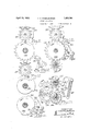
- Fig. 9 is a section taken on the line 9 9 of Fig. 4;
- Fig. 10 is a section taken on the line 10-10 of Fig. 4;
- Fig. 11 is a section taken on the line 11-11 of Fig. 4;
- Fig. 12 is a section taken on Serial N0. 28,552.
- the totalizing mechanism is mounted in a frame 246 supported in the side members of the y supplemental frame 245.
- the bank of total adding counters includes a units counter 247, a tens counter 24S and a hundreds counter 249.
- suoli other counters as may be necessary to impart to the total adder the desired capacity and in the present de- 'ice, I have provided three additional countcrvvheels, as shown at 250, Which are connected With the hundreds countervvheel 249 through the usual transfer mechanism.
- the units and tins and hundreds counterwheels are independently operable and actuating means are provided for the respective countervvheels which Will cause each counterivheel ci the total adder to record the item which is registered on the corresponding counter- Wheel of the registering mechanism.
- This actuating mechanism consists of a separate selecting device for each of the three counterwheels oi the total adder, suitable means being provided for controlling the position of this selecting device.
- the actuating mechanism further comprises means for causing to be added to the tota-l adder an amount determined lby the position of the selecting device.
- each selecting device comprises a rotary supporting member, such as a disk 251, rotatably mounted on a stationary shaft 252 mounted in the supplemental frame and which has mounted thereon a series of pinions 253.
- These pinions are nine in number and are mounted on the face of the disk, concentric with the axis thereof.
- the axes of the pinions are spaced apart such distances that the pinions do not engage one with the other and the first and last pinions of the series are separated by a space substantially equal to the space occupied by one of the pinions.
- Each pinion is rotatably mounted on a short shaft, or stud, 254 rigidly mounted in the disk and this stud has an end portion 255 which projects beyond the face of the pinion.
- a stud 256 Mounted in the space between the first and last pinions of the series is a stud 256, which indicates the zero positionrof the totalizer and the axis of which is -spaced equa-l distances from the axes of the adjacent pinions and the outer end of which projects from the disk substantially the same distance as the ends of the studs 255.
- Each pinion has, in the present construction, twelve teeth and each pinion has projecting from one face thereof one or more laterally extending lugs or teeth, as shown at 257 in Figs.
- each succeeding pinion having one more of these laterally extending lugs than the preceding pinion, so that the first pinion of the series has one laterally extending tooth while the last pinion of the series has nine such teeth, and these teeth govern the number of units added to the corresponding counterwheel of the total adder.
- each supporting device or disk 251 may be rotated through an operative connection with the corresponding setting device of a registering mechanism to bring that pinion which corresponds to the item which is to be registered into operative relationA with the total adder.
- the operative position of the pinion is directly beneath the axis of the disk 251.
- Each disk 251 has secured thereto a gear 258 and the gear of the selecting disk for the units counter of the total adder is arranged to mesh with a gear 259 rigidly secured to the shaft 31.
- the position of the selecting device is controlled by the setting mechanism of a fare register, which is shown as a whole at A in Fig. 1, and which is fully described in the above mentioned application.
- the mechanism there shown comprises a hundreds setting lever 23, a tens setting lever 24 and a units setting lever 25, which levers have geared connections with the respective registering elements and with the corresponding hand or units selecting device.
- the lever 25 is connected with a gear 40 which is mounted on a shaft 27 and meshes with a gear 41 on the shaft 31, the gear 41 being connected with the gear 259.
- the selecting disk for the units counterwhcel of the total adder will be actuated to a like extent so that upon the further operation of the device the same item will be added to the total adder or counter.
- the gears 258 of the selecting disks for the tens and hundreds counterwheels of the total adder have, respectively, geared connections with the levers 24 and 23, which connections are similar to that above described but are not here shown.
- each of the three selecting devices is controlled through geared connections with the corresponding setting levers 23, 24 and 25, and in each instance the ratio of the gear train is such that the selecting device will be moved to a position corresponding to the position of the lever and therefore corresponding to the item registered by the corresponding indicator drum ent instance, is their lowerinost position.
- the laterally extending actuating teeth or lugs 257 of the several selectin@ ⁇ pinions are arranged to engage and actuate a gear 281 which is rotatably mounted on a shaft 282 supported in the side members of the frame 245, which shaft is also supported at points between its ends in bearing plates 283.
- This gear or idler 281 is in mesh with a driving pinion 284i for the total adder-s secured to or formed integral with a hub 285 which carries the corresponding counterwheel for the total adder and which may be either the units counterwheel 273, the tens counterwheel 24:8 or the hundreds counterwheel 249, deiiending upon which selecting disk is actuated, it being understood that the selecting disks and their associated mechanisms are identical and for that reason it will b-e necessary to describe but one of them.
- @perating movement is imparted to the selecting pinion 253, about individual axis, by means of a mutilated gear 286 which has suiicieut teeth to cause a complete rotation to be im part-ed to the selecting pinion 253 upon each rotation of the mutilated gear.
- This mutilated gear 286 is rigidly secured to the shaft 282 which carries a gear 287 ⁇ which me with a gear 288 on the main operati 73, which is also provided with a pi- I 10G which meshes with a reciprocatory i bar ft connected through a lever 107 anoL rod 1108 with afoot lever 109, by means of which operative movement may be imparted to the operating shaft 73.
- the pinion 108 is provided with clutch mechanism not shown so that the pinion 106 is operatively connected to the shaft 73 as the racl l 4f moves npwardly but idly rotates thereon as the racl; 104i moves downwardly so that the shaft 282 is given one complete rotation as the rari; 104 moves upwardly and is stationary as the rack moves downwardly.
- lt will apparnt, therefore, that during the setting opei tion of the register one or more of the selecting devices will be actuated and the proper selecting pinions brought into operativo relation with the corresponding counterwheels of the total adder and then, upon the operation of the reciprocatory bar of the registering device, the selected p.
- a locking arm 289 is n'iounted ou s i f5) and provided with a hook .ped c ed to be moved into and out of enga with the studs 255 and 256 on the disk. Rigidly connected with the ai" an arm 291 which carries a pin 292 adapted to travel in a cam slot 293 formed in a disk 29d mounted on the shaft 282.
- the three arms 289 are all secured to the shaft 29() and that this shaft is rocked by the single arm 291, so that the three lockinn' arms are moved simultaneously into and out of their locking positions.
- the shape of the cam surface in the disk 29st is such that the locking arms will be held in their locking positions during l f eater part of the rotation of the shaft 282. rl"he several selecting pinions each has al tooth partly cut away so as to provide a recess 295, as shown in Fig. 15, which recess will be in the outermost position when the pinion is in its normal or locked position.
- This cut away tooth or recess provides a space between the teeth of the pinion to receive the curved surface of a locking cam 296, which is carried by a sleeve 297 secured to the shaft- 282 and is so arranged with relation to the driving gear 286 for the pinion that it will be brought into engagement with the pinion immediately after that gear moves out of engagement therewith, thus instantly checking the movement of the pinion and preventing the overthrow thereof.
- the idle or connecting gear 281 between the selecting pinion and the actuating gear for the total adder, is also locked against movement immediately upon the completion of its operation by the pinion.
- detent or pawl 298 having a nose at each end, the two noses being offset and one, as shown at 299, being arranged to engage the teeth of the gear 281 and to enter the space between the teeth and lock the gear against rotation.
- the nose 300 at the other end of the pawl is otset from the nose 299 and is arranged to be engaged by the periphery of a cam 301 carried by the hub or sleeve 297 on the shaft 282, and which therefore rotates with the shaft.
- the cam is so shaped that during the period that the gear 281 is being rotated by the pinion 253 the nose 300 of ⁇ he pawl will be out of engagement with the periphery of the cam and the pawl will ride over the teeth of the gear, the nose 299 being held in engagement with the teeth by means of a spring 302.
- the higher portion of the p-riphery of the cam is brought into engagement with the nose 300 of the pawl and the pawl is held against rocking movement with the nose 299 in position between two of the teeth of the gear, thus positively locking the latter against movement.
- each counterwheel, or type wheel, of the total adder is individually actuated to set up thereon the item which has been registered, it is necessary for means to be provided for transferring the count from the counterwheels of lower denomination to the counterwheels of higher denomination.
- suitable transfer mechanisms each of which consists of a gear 303 mounted on a stud 304 andY meshing with a pinion 305 which is carried by the sleeve 297 which in turn is secured to the shaft 282.
- the other arm of the bell crank lever, as shown at 308, is provided with notches 310 adapted to be engaged by a spring pressed Vpawl 311 to hold the pinion 306 either in its operative or inoperative position. Dnring the normal operation of the counterwheel the pinion 306 will be in inoperative relation to the total adder but when the counterwheel of lower denomination is moved to its ninth position a tooth 312 carried thereby will engage a projection 313 on the arm 308 of the bracket and force that arm upwardly and thereby bring the pinion 306 into operative relation with the counterwheel of next higher denomination.
- the pinion 306 does not mesh with the driving pinion 284 for the counterwheel of next higher denomination but it has thereon al lateral projection extending from one of its teeth and constituting a single operating tooth, as shown at 314, which will engage the carrying pinion 314@ secured to the hub 285 to advance the same one point. lVhen the counterwheel of higher denomination has been advanced, a single tooth 315, secured to the pinion 305 on the shaft 282, will engage the projection 316 on the upper edge of the arm 308 and force the arm downwardly to move the pinion 306 into its inoperative position.
- the recess in the tens cam is located in advance of the recess 317 in the hundreds locking cam, thus the tens counterwheel will be actuated first and should the transfer to this counterwheel also involve a transfer from the tens counterwheel to the hundreds counterwheel this can take place subsequently.
- the shaft 282 makes one complete revolution as the rack bar 104 moves upwardly and is held stationary While the bar 104 moves downwardly.
- the rotation of the shaft 282 and the gear 286 secured thereto is in the direction of the arrow (Fig. 9).
- no teeth thereof come into contact with the teeth of the selector pinion 253 driving the gear 281 as many spaces as there are lugs 257 on the selector pinion 253 and in case the tooth 312 engages the projection 313 on what is known as a carrying operation in addition, the pinion 306 is moved into such a position that its carrying tooth 314 will subsequently engage and actuate the gear 314@ on the sleeve 285 of the counter of next higher denomination.
- totalizer wheels, totalizer gears therefor means whereby any number may be added to the number previously recorded on said totalizer wheels, said means including carrying mechanism, a lever and a pinion thereon forming a part of said carrying mechanism, means whereby said pinion is rotated, means whereby said lever is shifted when its corresponding totalizer wheel is rotated beyond 9 so as to move the axis of said pinion toward the totalizer gear of next higher order and means to advance thereafter the totalizer wheel of next higher order one unit by the continued rotation of said pinion.
- totalizer wheels, totalizer gears therefor means whereby any number may be added to the number previously recorded on said totalizer wheels, said means including carrying mechanism, a lever and a pinion thereon forming a part of said carrying mechanism, means whereby said pinion is rotated, means whereby said lever is shifted when its corresponding totalizer wheel is rotated beyond 9 so as to move the axis of said pinion toward the totalizer gear of next higher order, means to advance thereafter the totalizer wheel of next higher order one unit by the continued rotation of said pinion and means to thereafter shift said lever so as to move the axis of said pinion away from said gear.
- carrying mechanism including a pivoted lever, a pinion carried by said lever, means to shift said lever and thereby move the axis of said pinion on carrying operations and means other than said lever to rotate said pinion to carry.
- totaliZer wheels, totalizer gears therefor means whereby any number may be added to the number previously recorded on said totaliZer wheels, said means including carrying mechanism, a lever and a pinion thereon forming a part of said carrying mechanism, means whereby said pinion is rotated, means whereby said lever is shifted when its corresponding totalizer wheel is rotated beyond 9 so as to move the axis of said pinion toward the totalizer gear of next higher order, means to advance thereafter the totalizer wheel of next higher order one unit by the continued rotation of said pinion, means to thereafter shift said lever so as to move the axis of said pinion away from said gear.
- carrying mechanism including a pivoted lever, a pinion carried by said lever, means to shift said lever and thereby move the axis of said pinion on carrying operations and means to hold said lever in shifted position until the carrying operation has been completed and means to actuate said pinion while in its shifted position to effect carrying.
- totalizer wheels, totalizer gears therefor means whereby any number may be added to the number previously recorded on said totalizer wheels, said means including carrying mechanism, a lever and a pinion thereon forming a part of said carrying mechanism, means whereby said pinion is rotated, means whereby said lever is shifted when its corresponding totalizer wheel is rotated beyond 9 so as to move the axis of said pinion toward the totalizer gear of next higher order, means to advance thereafter the totalizer wheel of next higher order one unit by the continued rotation of said pinion, means to thereafter shift said lever so as to move the axis of said pinion away from said gear, and resilient means tending to hold said lever in either of its shifted positions.
- totalizer gears means whereby said gears are actuated on non-carrying operations, a lever, a pinion carried thereby, means whereby the axis of said pinion is shifted toward the axis of said gears on carrying operations and means to effect carrying to the next higher order through said pinion after it is shifted.
- units and tens counters drive pinions operatively connected with said counters, a carrying pinion connected to said tens counter, means whereby each of said driving pinions are actuated to operate said counters, a pivoted lever, a pinion mounted thereon, means whereby the units counter shifts said lever so as to bring said last mentioned pinion into engagement with said tens counter, and other means than said lever whereby said pinion is thereafter rotated to carry.
Landscapes
- Physics & Mathematics (AREA)
- Engineering & Computer Science (AREA)
- Mathematical Physics (AREA)
- Computer Hardware Design (AREA)
- Computing Systems (AREA)
- General Physics & Mathematics (AREA)
- Theoretical Computer Science (AREA)
- Transmission Devices (AREA)
Description
April l2, 1932,. A. s. WHEELBARGER ADDING MECHANI SM Filed May 7, 1925 5 Sheets-Sheet l i EL VVE/v TOR. 9,4. 5. WHEEL BA Ref/P. e*
Tram/5y April 12, 192.2.-
A-` S. WHEELBARGER ADDING MEGHANI SM Filed May 7, 1925 5 Sheets-Sheet 2 r ATTORNEY April 12, 1932. A A.4 s. WHEELBARGER ADDING MECHANISM 5 Sheets-Sheet 3 Filed May 7, 1925 April 12, 1932- A. s. WHEELBARGER .1,853,791
ADDING MECHANI SM Filed May 7, 1925 5 Sheets-Sheet 5 ATToP/VEY Patented Apr. 12, 1932 UNITED STATES PATENT OFFICE ALBERT S. WHEELBARGER, F DAYTON, OHIO, ASSIGNOR TO OHMER FARE REGISTER COMPANY, OF DAYTON, OHIO ADDING MECHANISM Original application led December 31, 1924, Serial No. 759,170. Divided and this application filed May 7,
This invention relates to adding mechanisms and more particularly to a total addei for computing and registering the total value of a plurality of items as such items are regisltered under a registering or computing device; and is a division of the application for patent filed by me December 31, 1924, Serial No. 759,170.
One object of the invention is to provide v an adding' mechanism Which will compute and register in penny multiples the total value of items or" any amount Within the capacity of the machine.
A further object of the invention is to provide such a mechanism which will be simple in its operation, accurate in its computation,
and of such a character that it will not be easily disarranged or rendered inoperative.
@ther objects of the invention Will appear 0 as the mechanism is described in detail.
In the accompanying drawings Fig. 1 is a side elevation, partly broken away, oi' a fare registering mechanism having my invention embodied therein; Fig. 2 is a rear elevation of a portion of said fare registering mechanisin showing the setting levers; Fig. 3 is a transverse vertical sectional view of an adding mechanism embodying my invention, showing the several parts in elevation; Fig.
4 is a section taken on the line 4 4 of FiO. 3;
Fig. 5 is a section taken on the line 5 0 of Fig. 3; Fig. 6 is an elevation of a portion oLt' the actuating mechanism for the total adder; Fig. 7 is a section taken on the line 7-7 of Fig. 3; Fig. 8 is a detail view of the actuating cam for the lock for the selecting device; Fig. 9 is a section taken on the line 9 9 of Fig. 4; Fig. 10 is a section taken on the line 10-10 of Fig. 4; Fig. 11 is a section taken on the line 11-11 of Fig. 4; Fig. 12 is a section taken on Serial N0. 28,552.
able members, each having a different value, and each being movable into operative relation to the counter, means being provided for actuating the selecting device and for causv ing that member thereof which is in operative relation to the counter to actuate the counter to add thereto the value of that particular member. It will be understood, however, that this particular embodiment has been chosen for the purpose of illustration only, that the device may take various forms Without departing from the spirit of the in vention and, further, that While the present device Was designed primarily for use in con- 1 nection with a fare register or like mechanism it is not limited to use in connection with other registering devices.
In -that form of the device here shown the totalizing mechanism is mounted in a frame 246 supported in the side members of the y supplemental frame 245. The bank of total adding counters includes a units counter 247, a tens counter 24S and a hundreds counter 249. In addition to these three counters there may be added suoli other counters as may be necessary to impart to the total adder the desired capacity and in the present de- 'ice, I have provided three additional countcrvvheels, as shown at 250, Which are connected With the hundreds countervvheel 249 through the usual transfer mechanism. The units and tins and hundreds counterwheels are independently operable and actuating means are provided for the respective countervvheels which Will cause each counterivheel ci the total adder to record the item which is registered on the corresponding counter- Wheel of the registering mechanism. This actuating mechanism consists of a separate selecting device for each of the three counterwheels oi the total adder, suitable means being provided for controlling the position of this selecting device. The actuating mechanism further comprises means for causing to be added to the tota-l adder an amount determined lby the position of the selecting device. In the present mechanism each selecting device comprises a rotary supporting member, such as a disk 251, rotatably mounted on a stationary shaft 252 mounted in the supplemental frame and which has mounted thereon a series of pinions 253. These pinions are nine in number and are mounted on the face of the disk, concentric with the axis thereof. The axes of the pinions are spaced apart such distances that the pinions do not engage one with the other and the first and last pinions of the series are separated by a space substantially equal to the space occupied by one of the pinions. Each pinion is rotatably mounted on a short shaft, or stud, 254 rigidly mounted in the disk and this stud has an end portion 255 which projects beyond the face of the pinion. Mounted in the space between the first and last pinions of the series is a stud 256, which indicates the zero positionrof the totalizer and the axis of which is -spaced equa-l distances from the axes of the adjacent pinions and the outer end of which projects from the disk substantially the same distance as the ends of the studs 255. Each pinion has, in the present construction, twelve teeth and each pinion has projecting from one face thereof one or more laterally extending lugs or teeth, as shown at 257 in Figs. 3 and 15, each succeeding pinion having one more of these laterally extending lugs than the preceding pinion, so that the first pinion of the series has one laterally extending tooth while the last pinion of the series has nine such teeth, and these teeth govern the number of units added to the corresponding counterwheel of the total adder. To this end each supporting device or disk 251 may be rotated through an operative connection with the corresponding setting device of a registering mechanism to bring that pinion which corresponds to the item which is to be registered into operative relationA with the total adder. In the present instance, the operative position of the pinion is directly beneath the axis of the disk 251. Each disk 251 has secured thereto a gear 258 and the gear of the selecting disk for the units counter of the total adder is arranged to mesh with a gear 259 rigidly secured to the shaft 31. In the present machine the position of the selecting device is controlled by the setting mechanism of a fare register, which is shown as a whole at A in Fig. 1, and which is fully described in the above mentioned application. The mechanism there shown comprises a hundreds setting lever 23, a tens setting lever 24 and a units setting lever 25, which levers have geared connections with the respective registering elements and with the corresponding hand or units selecting device. To this end the lever 25 is connected with a gear 40 which is mounted on a shaft 27 and meshes with a gear 41 on the shaft 31, the gear 41 being connected with the gear 259. Consequently when the units setting lever is actuated to set the register according to the fare collected the selecting disk for the units counterwhcel of the total adder will be actuated to a like extent so that upon the further operation of the device the same item will be added to the total adder or counter. The gears 258 of the selecting disks for the tens and hundreds counterwheels of the total adder have, respectively, geared connections with the levers 24 and 23, which connections are similar to that above described but are not here shown. It will be apparent therefore that each of the three selecting devices is controlled through geared connections with the corresponding setting levers 23, 24 and 25, and in each instance the ratio of the gear train is such that the selecting device will be moved to a position corresponding to the position of the lever and therefore corresponding to the item registered by the corresponding indicator drum ent instance, is their lowerinost position. To j permit each pinion to be rotated when in its operative position, I have provided the stationary locking disk 273 with a recess 274 in the lower portion thereof and in order to prevent the accidental rotation of the pinion which is in its operative position I have slidably mounted on the locking disk a plate 275, the edge of which is curved to conform to the edge of the locln'ng disk so that in effect it forms a part of that locking disk. This plate is, however, yieldably mounted and, as here shown, the inner end-thereof is slotted at 276 so as to embrace the hub 277 which carries the disk 273. Springs 278 connected with the plate 275 and with a stud 27 9, secured to the disk 273 and extending through a slot 280 in the plate 275, tend to move the plate outwardly and to hold the same against inward movement, the outward movement of the plate being limited by the contact of the same with the stud 27 9. Vith the plate in its outermost position the selecting pinions will move about the locking disk with a planetary movement and will be held against rotation about their individual axes during this movement. When the selecting disk is stopped with one of the pinions in operative position, that pinion will be held against rotation only by the yieldable plate 275 and when force is applied to the pinion this plate will yield to permit the pinion to rotate.
The laterally extending actuating teeth or lugs 257 of the several selectin@` pinions are arranged to engage and actuate a gear 281 which is rotatably mounted on a shaft 282 supported in the side members of the frame 245, which shaft is also supported at points between its ends in bearing plates 283. This gear or idler 281 is in mesh with a driving pinion 284i for the total adder-s secured to or formed integral with a hub 285 which carries the corresponding counterwheel for the total adder and which may be either the units counterwheel 273, the tens counterwheel 24:8 or the hundreds counterwheel 249, deiiending upon which selecting disk is actuated, it being understood that the selecting disks and their associated mechanisms are identical and for that reason it will b-e necessary to describe but one of them. @perating movement is imparted to the selecting pinion 253, about individual axis, by means of a mutilated gear 286 which has suiicieut teeth to cause a complete rotation to be im part-ed to the selecting pinion 253 upon each rotation of the mutilated gear. This mutilated gear 286 is rigidly secured to the shaft 282 which carries a gear 287 `which me with a gear 288 on the main operati 73, which is also provided with a pi- I 10G which meshes with a reciprocatory i bar ft connected through a lever 107 anoL rod 1108 with afoot lever 109, by means of which operative movement may be imparted to the operating shaft 73. The pinion 108 is provided with clutch mechanism not shown so that the pinion 106 is operatively connected to the shaft 73 as the racl l 4f moves npwardly but idly rotates thereon as the racl; 104i moves downwardly so that the shaft 282 is given one complete rotation as the rari; 104 moves upwardly and is stationary as the rack moves downwardly. lt will apparnt, therefore, that during the setting opei tion of the register one or more of the selecting devices will be actuated and the proper selecting pinions brought into operativo relation with the corresponding counterwheels of the total adder and then, upon the operation of the reciprocatory bar of the registering device, the selected p. 'on will be rotated to attuate the correspom ng counterwheel of the total adder. Prior to rotation of the selected pinion the se disk is locked against rotation. To this end a locking arm 289 is n'iounted ou s i f5) and provided with a hook .ped c ed to be moved into and out of enga with the studs 255 and 256 on the disk. Rigidly connected with the ai" an arm 291 which carries a pin 292 adapted to travel in a cam slot 293 formed in a disk 29d mounted on the shaft 282. It will be noted that the three arms 289 are all secured to the shaft 29() and that this shaft is rocked by the single arm 291, so that the three lockinn' arms are moved simultaneously into and out of their locking positions. It will also be noted that the shape of the cam surface in the disk 29st is such that the locking arms will be held in their locking positions during l f eater part of the rotation of the shaft 282. rl"he several selecting pinions each has al tooth partly cut away so as to provide a recess 295, as shown in Fig. 15, which recess will be in the outermost position when the pinion is in its normal or locked position. This cut away tooth or recess provides a space between the teeth of the pinion to receive the curved surface of a locking cam 296, which is carried by a sleeve 297 secured to the shaft- 282 and is so arranged with relation to the driving gear 286 for the pinion that it will be brought into engagement with the pinion immediately after that gear moves out of engagement therewith, thus instantly checking the movement of the pinion and preventing the overthrow thereof. The idle or connecting gear 281, between the selecting pinion and the actuating gear for the total adder, is also locked against movement immediately upon the completion of its operation by the pinion. To this end I have mounted adjacent to the gear 281 a detent or pawl 298 having a nose at each end, the two noses being offset and one, as shown at 299, being arranged to engage the teeth of the gear 281 and to enter the space between the teeth and lock the gear against rotation.
The nose 300 at the other end of the pawl is otset from the nose 299 and is arranged to be engaged by the periphery of a cam 301 carried by the hub or sleeve 297 on the shaft 282, and which therefore rotates with the shaft.
The cam is so shaped that during the period that the gear 281 is being rotated by the pinion 253 the nose 300 of `he pawl will be out of engagement with the periphery of the cam and the pawl will ride over the teeth of the gear, the nose 299 being held in engagement with the teeth by means of a spring 302. At the completion of the operative movement of the gear the higher portion of the p-riphery of the cam is brought into engagement with the nose 300 of the pawl and the pawl is held against rocking movement with the nose 299 in position between two of the teeth of the gear, thus positively locking the latter against movement.
lVhile each counterwheel, or type wheel, of the total adder is individually actuated to set up thereon the item which has been registered, it is necessary for means to be provided for transferring the count from the counterwheels of lower denomination to the counterwheels of higher denomination. To this end I have-provided suitable transfer mechanisms, each of which consists of a gear 303 mounted on a stud 304 andY meshing with a pinion 305 which is carried by the sleeve 297 which in turn is secured to the shaft 282. Referring to Fig. 4, the following parts move in unison with the rack driven gear 287, namely, the shaft 282, the cams 301, locking cams 296, gears 285, sleeves 297, pinions 302 and locking cam 294, all of which parts malte one complete rotation each time the machine is operated. This complete rotation of each of the pinions 305 is transmitted through the gear 303 to a pinion 306 which is rotatably mounted on one arm of a bracket or bell crank lever 307 which is pivotally mounted on the stud 304 so that the swinging movement thereof will carry the pinion 306 toward and from the total adder. The other arm of the bell crank lever, as shown at 308, is provided with notches 310 adapted to be engaged by a spring pressed Vpawl 311 to hold the pinion 306 either in its operative or inoperative position. Dnring the normal operation of the counterwheel the pinion 306 will be in inoperative relation to the total adder but when the counterwheel of lower denomination is moved to its ninth position a tooth 312 carried thereby will engage a projection 313 on the arm 308 of the bracket and force that arm upwardly and thereby bring the pinion 306 into operative relation with the counterwheel of next higher denomination. The pinion 306 does not mesh with the driving pinion 284 for the counterwheel of next higher denomination but it has thereon al lateral projection extending from one of its teeth and constituting a single operating tooth, as shown at 314, which will engage the carrying pinion 314@ secured to the hub 285 to advance the same one point. lVhen the counterwheel of higher denomination has been advanced, a single tooth 315, secured to the pinion 305 on the shaft 282, will engage the projection 316 on the upper edge of the arm 308 and force the arm downwardly to move the pinion 306 into its inoperative position.
It is, of course, necessary that the gears 281 of the tens and hundreds counterwheels be released for operation during the transferring to these counterwheels of the count from the counters of lower denomination. I have therefore provided the locking disks 301 for the gears of the connterwheels of higher denomination with recesses, as shown at 316@ and 317 in Fig. 11. These recesses are so arranged in the respective locking cams that they will be brought into alinemcnt with the noses 300 of the corresponding pawls 298 at the time the transfer operation takes place. It will be noted that the recess in the tens cam, as shown at 31664, is located in advance of the recess 317 in the hundreds locking cam, thus the tens counterwheel will be actuated first and should the transfer to this counterwheel also involve a transfer from the tens counterwheel to the hundreds counterwheel this can take place subsequently.
As before mentioned the shaft 282 makes one complete revolution as the rack bar 104 moves upwardly and is held stationary While the bar 104 moves downwardly. The rotation of the shaft 282 and the gear 286 secured thereto is in the direction of the arrow (Fig. 9). During approximately the first 45o of rotation of the rotation of the gear 286 no teeth thereof come into contact with the teeth of the selector pinion 253 driving the gear 281 as many spaces as there are lugs 257 on the selector pinion 253 and in case the tooth 312 engages the projection 313 on what is known as a carrying operation in addition, the pinion 306 is moved into such a position that its carrying tooth 314 will subsequently engage and actuate the gear 314@ on the sleeve 285 of the counter of next higher denomination. All of the above is accomplished While the shaft 282 was being rotated through a little less than 27 0o and during said rotation the tooth 314 (Fig. 3) has been rotated through the pinions 305 and 303 to a position ready to engage the gear 314a provided the lever 307 has been tripped. If the lever 307 has been tripped the tooth 314 now engages the gear 3140i rotating it the distance of one tooth to carry or add to the counter of next higher denomination the number one. It is, of course, very important that this carrying operation take place subsequently to the rotation of the counters through the gear 281 for otherwise the gear 281 and the tooth 314 might simultaneously advance the counter with the result that the carrying would be accomplished.
It is furthermore important that carrying from units to tens should take place prior to the carrying from tens to hundreds. This is accomplished by arranging the units transfer tooth 314, shown in full lines in Fig. 3, one tooth in advance of the tens transfer tooth 314 shown in dotted lines.
The operation of the device will be readily understood from the foregoing description and it will be apparent that I have provided an adding device by means of which items of any odd value within the capacity of the machine may be added to the total adder or counter in penny multiples. This mechanism is of such a character that it may, if desired, be associated with other registering mechanisms and controlled thereby or may be used independently thereof and controlled in any suitable manner. The mechanism is simple in its construction, when the function thereof is considered; it is accurate in its computations; and is of such a character that the parts thereof will not be easily disarranged or rendered inoperative, the mechanism having been primarily designed for use on vehicles.
Vhile I have shown and described one embodiment of my invention I wish it to be understood that I do not desire to be limited to the details thereof as various modifications may occur to a person skilled in the art.
Having now fully described my invention, what I claim as new and desire to secure by Letters Patent, is
l. In a machine of the type described, totalizer wheels, totalizer gears therefor, means whereby any number may be added to the number previously recorded on said totalizer wheels, said means including carrying mechanism, a lever and a pinion thereon forming a part of said carrying mechanism, means whereby said pinion is rotated, means whereby said lever is shifted when its corresponding totalizer wheel is rotated beyond 9 so as to move the axis of said pinion toward the totalizer gear of next higher order and means to advance thereafter the totalizer wheel of next higher order one unit by the continued rotation of said pinion.
2. In a machine of the type described, totalizer wheels, totalizer gears therefor, means whereby any number may be added to the number previously recorded on said totalizer wheels, said means including carrying mechanism, a lever and a pinion thereon forming a part of said carrying mechanism, means whereby said pinion is rotated, means whereby said lever is shifted when its corresponding totalizer wheel is rotated beyond 9 so as to move the axis of said pinion toward the totalizer gear of next higher order, means to advance thereafter the totalizer wheel of next higher order one unit by the continued rotation of said pinion and means to thereafter shift said lever so as to move the axis of said pinion away from said gear.
3. In a totalizer, carrying mechanism including a pivoted lever, a pinion carried by said lever, means to shift said lever and thereby move the axis of said pinion on carrying operations and means other than said lever to rotate said pinion to carry.
4:. In a machine of the type described, totaliZer wheels, totalizer gears therefor, means whereby any number may be added to the number previously recorded on said totaliZer wheels, said means including carrying mechanism, a lever and a pinion thereon forming a part of said carrying mechanism, means whereby said pinion is rotated, means whereby said lever is shifted when its corresponding totalizer wheel is rotated beyond 9 so as to move the axis of said pinion toward the totalizer gear of next higher order, means to advance thereafter the totalizer wheel of next higher order one unit by the continued rotation of said pinion, means to thereafter shift said lever so as to move the axis of said pinion away from said gear.
5. In a totalizer, carrying mechanism including a pivoted lever, a pinion carried by said lever, means to shift said lever and thereby move the axis of said pinion on carrying operations and means to hold said lever in shifted position until the carrying operation has been completed and means to actuate said pinion while in its shifted position to effect carrying.
6. In a machine of the type described, totalizer wheels, totalizer gears therefor, means whereby any number may be added to the number previously recorded on said totalizer wheels, said means including carrying mechanism, a lever and a pinion thereon forming a part of said carrying mechanism, means whereby said pinion is rotated, means whereby said lever is shifted when its corresponding totalizer wheel is rotated beyond 9 so as to move the axis of said pinion toward the totalizer gear of next higher order, means to advance thereafter the totalizer wheel of next higher order one unit by the continued rotation of said pinion, means to thereafter shift said lever so as to move the axis of said pinion away from said gear, and resilient means tending to hold said lever in either of its shifted positions.
7. In a totalizer, totalizer gears, means whereby said gears are actuated on non-carrying operations, a lever, a pinion carried thereby, means whereby the axis of said pinion is shifted toward the axis of said gears on carrying operations and means to effect carrying to the next higher order through said pinion after it is shifted.
8. In a calculating machine, the combination of a gear, a counting wheel, means whereby said gear operates said counting wheel so as to add thereon any value from Zero to nine, carrying mechanism including a lever and a pinion mounted thereon, means whereby said lever is shifted to engage said pinion with said counting wheel, and means other than said lever to thereafter rotate said pinion to carry.
9. In a calculating machine, units and tens counters, drive pinions operatively connected with said counters, a carrying pinion connected to said tens counter, means whereby each of said driving pinions are actuated to operate said counters, a pivoted lever, a pinion mounted thereon, means whereby the units counter shifts said lever so as to bring said last mentioned pinion into engagement with said tens counter, and other means than said lever whereby said pinion is thereafter rotated to carry.
In testimony whereof, I affix my signature hereto.
ALBERT S. WHEELBARGER.
Publications (1)
| Publication Number | Publication Date |
|---|---|
| US1853791A true US1853791A (en) | 1932-04-12 |
Family
ID=3423660
Family Applications (1)
| Application Number | Title | Priority Date | Filing Date |
|---|---|---|---|
| US1853791D Expired - Lifetime US1853791A (en) | Adding mechanism |
Country Status (1)
| Country | Link |
|---|---|
| US (1) | US1853791A (en) |
Cited By (3)
| Publication number | Priority date | Publication date | Assignee | Title |
|---|---|---|---|---|
| US2537471A (en) * | 1951-01-09 | Uydfors | ||
| US2556762A (en) * | 1951-06-12 | Lydfors | ||
| US2832533A (en) * | 1958-04-29 | chall |
-
0
- US US1853791D patent/US1853791A/en not_active Expired - Lifetime
Cited By (3)
| Publication number | Priority date | Publication date | Assignee | Title |
|---|---|---|---|---|
| US2537471A (en) * | 1951-01-09 | Uydfors | ||
| US2556762A (en) * | 1951-06-12 | Lydfors | ||
| US2832533A (en) * | 1958-04-29 | chall |
Similar Documents
| Publication | Publication Date | Title |
|---|---|---|
| US1853791A (en) | Adding mechanism | |
| US1853054A (en) | A a morton | |
| US2344627A (en) | Computing machine | |
| US2318241A (en) | Calculating machine | |
| US2105640A (en) | Cash register | |
| US1832791A (en) | Calculating machine | |
| US2139718A (en) | Cash register | |
| US3076597A (en) | Gelling | |
| US2558631A (en) | Suter | |
| US1708189A (en) | Cash register | |
| US2722376A (en) | Grant c | |
| US2291853A (en) | Calculating machine | |
| US1260061A (en) | Calculating-machine. | |
| US2304329A (en) | Calculating machine | |
| US2280919A (en) | landsiedel | |
| US3243111A (en) | Two input counter unit | |
| US1874805A (en) | Cash register | |
| US1833467A (en) | Calgujlatihg mageiitb | |
| US503946A (en) | Cash register and indicator | |
| US1594749A (en) | Device for indicating the number of revolutions of rotating machine elements | |
| US2291136A (en) | avery | |
| US2206724A (en) | Calculating machine | |
| US1146983A (en) | Cash-register. | |
| US1551009A (en) | campana | |
| US2294949A (en) | Calculating machine |