US1853054A - A a morton - Google Patents
A a morton Download PDFInfo
- Publication number
- US1853054A US1853054A US1853054DA US1853054A US 1853054 A US1853054 A US 1853054A US 1853054D A US1853054D A US 1853054DA US 1853054 A US1853054 A US 1853054A
- Authority
- US
- United States
- Prior art keywords
- transfer
- wheel
- pinion
- gear
- moved
- Prior art date
- Legal status (The legal status is an assumption and is not a legal conclusion. Google has not performed a legal analysis and makes no representation as to the accuracy of the status listed.)
- Expired - Lifetime
Links
Images
Classifications
-
- G—PHYSICS
- G06—COMPUTING OR CALCULATING; COUNTING
- G06M—COUNTING MECHANISMS; COUNTING OF OBJECTS NOT OTHERWISE PROVIDED FOR
- G06M1/00—Design features of general application
- G06M1/14—Design features of general application for transferring a condition from one stage to a higher stage
- G06M1/143—Design features of general application for transferring a condition from one stage to a higher stage with drums
-
- G—PHYSICS
- G06—COMPUTING OR CALCULATING; COUNTING
- G06C—DIGITAL COMPUTERS IN WHICH ALL THE COMPUTATION IS EFFECTED MECHANICALLY
- G06C15/00—Computing mechanisms; Actuating devices therefor
- G06C15/26—Devices for transfer between orders, e.g. tens transfer device
Definitions
- This invention relates to a transfer mechanism for calculating machines. It relates particularly to a transfer mechanism of the planetary gear type and to one that is capable of borrowing as well as carrying so that it may be used for both subtraction and addition.
- the general'object of the invention is to a provide an improved transfer mechanism that will effect transfers efficiently, quickly and accurately.
- Another object is to provide an improved transfer mechanism of the planetary gear type that is capable of both borrowing and carrying.
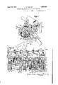
- Figure 1 is a sectional side elevation of the transfer mechanism showing portions thereof between the pinion'of units order and the pinion of next hi her order.
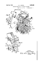
- Fig. 2 is a sectional front elevation of the transfer mechanism.
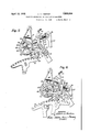
- FIG 3 is a perspective view of a portion of the transfer mechanism and its controls.
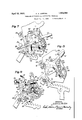
- Fig. 4.- is a reverse perspective of the controls shown at the left hand side of Fig. 3.
- Fig. 5 is a fragmentary sectional side elevation on the line 5 -5 of Fig. 2, the mechanism being shown conditioned to effect a carry and the parts being in the positions they occupy at just about the time a carry 1 is to take place.
- Fig. 6 is a view similar to Fig. 5 with the mechanism conditioned to effect a borrow 'and with the parts in the position they occupy at just about thetime a borrow is totake place.
- Fig. 7 is a' left side elevation showing the g I controls-forthe zeroizing mechanism.
- Fig. 8' is a view similar to Fig.7 with the zeroizing controls moved to position to restore the indicator dial to zero.
- Fig. 9 is a left sectional side elevation showing the indicator dials and the transfer mechanism restored to zero by the zeroizing mechanism.
- the transfer mechanism is shown associated with the register or counter of a cal culating machine, the details of the latter not being. shown as an understanding of them is not necessary for an understanding of the present invention.
- the counter comprises a plurality of counter pinions 10 rotatably mounted on a shaft 11, each pinion being adapted to be engaged by an actuator rack or segment 12.
- the actuator racks are normal- 1y out of engagement with the pinions but, when the machine is operated, they are raised into engagement and then moved either forward or backward to rotate the pinions.
- the racks are moved to the left as shown in Fig. 5 which rotates the pinions 10 clockwise.
- the actuator racks are moved to the right as shown in Fig. 6 which rotates the pinions 10 counterclockwise.
- the counter pinions are thus locked against ed to rotate with it which meshes with a gear to 9, inclusive, as illustrated in Fi 21 pivoted on a cross shaft 22, the latter being supported in the sideplates 23 (Fig. 2).
- Each gear 21 has an arm 24 exten ing outwardly from its hub on which is journaled a pinion 25 in the nature of a planet gear that meshes with a normally stationary sun gear 26 and with an internal gear 27 to which the indicator dial or wheel 28 is attached, said indicator wheel bearing numbers from 0 2.
- the gear 26 of the units order is hel against turning by being mounted in the side plate 23 as shown in Fig. 2 and the gears 26 of the higher. orders are held against turning by mechanism that will be explained later.
- a transfer from one order to the next is effected by connections between the indicator wheels of the different orders. These connections are alike as between the different orders and to avoid confusion only one will be explained, it being understood that the others are duplicates.
- the indicator wheel has a spider30 connected to a pinion or sun gear 31 which is journaled on the shaft 22.
- This pinion meshes with a planet gear or pinion 33 (Fig.
- the transfer gear is fixed to a hub 38 journaled on the hub of arm 35 which swings on the shaft 22.
- the left hand end of the hub 38 has a pinion formed on it, the pinion being the pinion 26 for the tens order.
- This pinion meshes with a pinion 25 for the tens order carried by the tens gear 21.
- the transfer gear 37 is normally held against movement in either direction by two detents, an addition detent 40 and a subtraction detent 41, both of the detents'being held in position by a spring 42 connected be tween them.
- detents are positioned to engage projections .43 on the periphery of the transfer gear as illustrated in Fi 1, and they normally hold the numeral w eels of the counter in alignment.
- the detents may each be moved singly out of the path of the rojections by the end of the arm 35 whic .can be moved to the positions of Fig 5 and 6 to release either detent.
- each arm 35 is connected by a link to one arm 51 of a yoke-shaped member 52 pivoted on the short stud shaft 53 (Figs. 1 and 2) of which there is one for each order secured to the adjacent partition plate.
- the member 52 has another arm 54 to which one end of a spring 55 is connected, the other end of said spring being connected to a bail 56 that may be moved up and down to chan e the direction of action of all the springs y means of an arm 57.
- Gaming operation l0 and that it moves to rotate said pinion inion moves clockwise I clockwise.
- the gear 21 is rotate counterclockwise which carries the gear 25 counterclockwise around the stationary gear 26. This rotates the ar 27 countercloc wise and carries the in iiator dial 28 in the same direction which rotates the pinion 31 counterclockwise (Fig. 3).
- Counterclockwise rotation of pinion 31 tends to rotate pinion 33 together with shaft 34 and pinion 36 clockwise as viewed in Fig. 3. Since the transfer ear 37 is held stationary, the result is that t e pinion 36 travels on the inside of the transfer gear thereby moving the arm 35 counterclockwise. Counterclockwise movement of arm 35 moves the link 50 to the right as viewed in Figs.
- said arm being between the tens and the hundreds orders.
- Carries from the tens to the hundreds order, from the hundreds to the thousands order, etc. take place the same way, it being understood that the gears 26- for the orders other than the units order are not held against rotation by the frame, but because the transfer gear 37 for the preceding order is held against rotation.
- the indicator wheels are visualized as the counter or register pinions, these wheels may be said to be advanced one step when a transfer takes place but, even in this event, it is not necessary to disengage the wheels from the actuator racks or fro lnthe pinionsthat drive them before a transfer can take place.
- the rotation of the counter pinions stores energ in the springs which later effect the trans era.
- the entire mechanism is geared together so as to make its movements positive and accurate thereby avoiding difficulties that sometimes occur in transfer mechanisms having a plurality of pawls,latches and detents. With the present invention it is not necessary to work to such close limits in order to have the transfer mechanism operate efliciently.
- Rotation of a pinion 10' tends to rotate the gearing mechanism connected to it in the opposite direction to that previously described thereby tending to move the arm 35 clockwise instead of counterclockwise.
- the arm 35 engages the subtraction pawl 41 and moves it out of the path of the detent 43 on the transfer gear 37 so as to free said gear to rotate counterclockwise.
- the gear is urged counterclockwise by the action of the spring 55 on the arm 35 with the result that, when said gear is released, it moves a step counterclockwise thereby rotating the indicator dial of next higher order clockwise, that is, it subtracts one unit from said dial.
- Zeroz'ez'ng mechanism It is not necessary to restore the transfer mechanism to normal after a transfer has taken place because said mechanism moves back to normal in effecting a transfer. It is necessary, however, to return the numeral dials to zero after a series of calculations has taken place and, for this purpose, a zeroizing mechanism is provided.
- the zeroizing mechanism is operated by a lever 60 having a finger piece 61.
- This lever is an extension of a cam plate 62 fixed to a cross shaft 63 that extends between and is journaled in the side plates 23.
- This shaft is semicircular in cross section as illustrated in Fig. 3, and it is located relative to the aligning pawls 13 so that, when the shaft is turned from its Fig. 1 to its Fig. 9 position, it moves the pawls rearward to free the pinions 10.
- This shaft has a series of curved projecting fingers 64 on it which, when the shaft is turned clockwise, engage extensions on the yokes 52, as illustrated in Fig. 8, to rock said yokes clockwise to push the links to the left as viewed in Fig. 1.
- the cam plate 62 is urged clockwise by a spring 65, (Fig. 4), the cam being limited in its movement by the engagement of the lever with a stud 66 on one arm of a member 67 fixed to a shaft 68.
- the other arm of the member it does not interferewith the action of the pawls 13 or the yokes 52.
- the stop arms 70 are also out of the paths of the stops 71 so that there is no interference with movement of the indicator wheels.
- the lever 60 is raised upwardly from the position of Fig. 7 to that of Fig. 8.
- the shaft 63 is turned clockwise as viewed in Fig. 3 or counterclockwise as viewed in Fig. 7, which results in rocking the pawls 13 rearwardly to free the pin-- ions 10.
- the curved arms 64 engage the yokes 52 and rock them counterclockwise as viewed in Fig. 7.
- the cam plate 62 pushes the stud 69 upward and rocks the shaft 68 clockwise as viewed in Fig. 7 to the position illustrated in Fig. 8 where the sto arms 70 are in the paths of the stops 71.
- the transfer gears 37 are held stationary by the detents 40 and 41, it being understood that the actuator racks 12 are disengaged from the pinions 10.
- the links 50 move to the left (Fig. 1) and the arms 35 are rocked clockwise.
- the clockwise movement of the arms 35 results in counterclockwise rotation of the pinions 36 and 33 which are connected to the same shaft 34.
- the movement continues until the indicator dials are returned'to their zero positions where they are arrested by the engagement of the stops 71 with the stop arms 70.
- the parts are proportioned so that the movement of the I curved arm 64 is just enough to move all the links 50 forward far enough to rotate the indicator dials to zero and to return the arms 35 to normal.
- lever 60 When the lever 60 is released it is returned to normal by spring 65 and the arm 81 is returned by a spring 83. The return of lever 60 returns to normal the shaft 63 with its arms 64 as well as shaft 68 with its arms 70. This frees the aligning pawls 13 which move to position to hold the pinions 10 against movement.
- a transfer mechanism for calculating machines the combination of two adjacent numeral wheels, a transfer member geared to the wheel of lower order and movable therewith in proportion to the movement of said lower order wheel, gearing con, nections between said transfer member and the numeral wheel of higher order, detent mechanism for normally restraining movement of said gearing connections, and means tensioned by said transfer member when it is moved for returning the member to normal position, said member acting, after it has been moved a predetermined distance by said lower order wheel, to release said detent mechanism to permit said tension means to return said transfer member to normal, said gearing connections between ,said transfer member and said numeral wheel of higher order serving, when the transfer member is-returned to normal, to move said higher order numeral wheel to effect a transfer.
- a transfer mechanism for calculating machines the combination of two adjacent numeral wheels, gearing mechanism connecting one wheel in tra in with the other, said gearing mechanism having a portion thereof placed under tension by movement of the wheel-of lower order, means for releasing said tensioned portion for sudden movement as said lower order wheel moves through its zero position, andmeans for conditioning said gearing mechanism to cause said sudden movement of said portion to be either a forward or a backward movement whereby either a carryv or a borrow may. be effected.
- Inja'transfer mechanism for calculating machines the combination of two' adjacent numeral wheels, a transfer wheel normally held against movement either forward or backward, gearing connections between said transfer wheel and the numeral wheel of gearin connection with the numeral wheel of hig er order, a detent mechanism normally preventing said transfer wheel from moving either forward or backward, a transfer membergeared to said transfer wheel, a
- a transfer mechanism for calculating machines the combination of two adjacent numeral wheels, a transfer wheel having a planetary gearing connection with the numeral wheel of higher order, said transfer wheel having a plurality of stops on its periphery, detents cooperating with said stops to normally prevent movement of said wheel either forward or backward, a pivoted transfer member carrying a gear meshing with teeth on the interior of said transfer wheel, a planetary gearing connection between said gear carriedby said transfer member and said numeral wheel of lower order whereby said transfer member is moved either forward or backward depending upon the direction of movement of said wheel of lower order, spring means tending to return said transfer member to normal, and means for changing the direction of action of said order, means tensioned by movement of said transfer member adapted to return said member to normal in a direction opposite that in which it is moved by said lower order numeral wheel, and a detent mechanism for Ezevntin movement of said transfer memr from eing transmitted to the wheel of higher order until said lower order numeral wheel moves through its zero position, said
Landscapes
- Physics & Mathematics (AREA)
- Engineering & Computer Science (AREA)
- General Physics & Mathematics (AREA)
- Theoretical Computer Science (AREA)
- Mathematical Physics (AREA)
- Computer Hardware Design (AREA)
- Computing Systems (AREA)
- Transmission Devices (AREA)
Description
April 12, 1932. HORTON 1,853,054
TRANSFER MECHANISM FOR CALCULATING MACHINES Filed Aug. 11, 1928 4 Sheets-Sheet 1 35 INVENTOR M mam, 01% v ATTCRNEY April 12, 1932. A. A. HORTON TRANSFER MECHANISM FOR CALCULATING MACHINES Filed Aug. 11, 1928 4 Sheets-Sheet 2 BY 4%, 06 4444,] *4/44? ATTORNEY April 12, 1932.
A. A. HORTON TRANSFER MECHANISM FOR CALCULATING MACHINES Filed Aug. 11, 1928 INVENTOR mama h'rlan 4 Sheets-Sheet 3 A il 12, 1932. A. A" HORTON 1,853,054
TRANSFER MECHANISM FOR CALCULATING MACHINES Filed Aug. 11, 1928 4 Sheets-Sheet 4 INVENTOR Patented Apr. 12, 1932 UNITED STATES. PATENT OFFICE ALLEN A. HORTON, OF PLYMOUTH, MICHIGAN, ASSIGNOR TO BURROUGHS ADDING MACHINE COMPANY, OF DETROIT, MICHIGAN, A CORPORATION 01'' MICHIGAN TRANSFER MECHANISM FOR CALCULATING MACHINES Application filed August 11, 1928. Serial No. 298,918.
This invention relates to a transfer mechanism for calculating machines. It relates particularly to a transfer mechanism of the planetary gear type and to one that is capable of borrowing as well as carrying so that it may be used for both subtraction and addition.
The general'object of the invention is to a provide an improved transfer mechanism that will effect transfers efficiently, quickly and accurately.
. Another object is to provide an improved transfer mechanism of the planetary gear type that is capable of both borrowing and carrying.
Other objects and advantages of the invention will appear from the following specification and drawings.
An embodiment of the invention is shown in the accompanying drawings in which;
Figure 1 is a sectional side elevation of the transfer mechanism showing portions thereof between the pinion'of units order and the pinion of next hi her order.
Fig. 2 is a sectional front elevation of the transfer mechanism.
3 is a perspective view of a portion of the transfer mechanism and its controls.
Fig. 4.- is a reverse perspective of the controls shown at the left hand side of Fig. 3.
Fig. 5 is a fragmentary sectional side elevation on the line 5 -5 of Fig. 2, the mechanism being shown conditioned to effect a carry and the parts being in the positions they occupy at just about the time a carry 1 is to take place.
Fig. 6 is a view similar to Fig. 5 with the mechanism conditioned to effect a borrow 'and with the parts in the position they occupy at just about thetime a borrow is totake place.
Fig. 7 is a' left side elevation showing the g I controls-forthe zeroizing mechanism.
Fig. 8' is a view similar to Fig.7 with the zeroizing controls moved to position to restore the indicator dial to zero.
Fig. 9 is a left sectional side elevation showing the indicator dials and the transfer mechanism restored to zero by the zeroizing mechanism.
The transfer mechanism is shown associated with the register or counter of a cal culating machine, the details of the latter not being. shown as an understanding of them is not necessary for an understanding of the present invention. The counter comprises a plurality of counter pinions 10 rotatably mounted on a shaft 11, each pinion being adapted to be engaged by an actuator rack or segment 12. The actuator racks are normal- 1y out of engagement with the pinions but, when the machine is operated, they are raised into engagement and then moved either forward or backward to rotate the pinions. In performing addition the racks are moved to the left as shown in Fig. 5 which rotates the pinions 10 clockwise. In performing subtraction the actuator racks are moved to the right as shown in Fig. 6 which rotates the pinions 10 counterclockwise. While the actuator racks are out of engagement with the pinions, the pinions are held against rotation by aligning pawls 13 pivoted on a cross shaft 14, each pawl being urged clockwise by a spring 15. Each pawl has a projecting nose 16 for engaging the space between the teeth of its counter pinion to hold the counter pinion against rotation. After the actuator racks are moved into engagement with the pinions, the pinions are released for rotation by means of a bail 17 which engages the tails 18 of all of the pawls 13. The bail is moved to the right from the position of Fig. 1. to that of Fig. 5 to move all of the pawls to the Fig. 5 position to permit rotation of the counter pinions. Before the actuator racks are moved out of engagement with-the counter pinions the bail17 moves to the left again and allows all the pawls 13 to move to normal position to hold their counter pinions in the new position towhich the latter may have been rotated.
The counter pinions are thus locked against ed to rotate with it which meshes with a gear to 9, inclusive, as illustrated in Fi 21 pivoted on a cross shaft 22, the latter being supported in the sideplates 23 (Fig. 2). Each gear 21 has an arm 24 exten ing outwardly from its hub on which is journaled a pinion 25 in the nature of a planet gear that meshes with a normally stationary sun gear 26 and with an internal gear 27 to which the indicator dial or wheel 28 is attached, said indicator wheel bearing numbers from 0 2. The gear 26 of the units order is hel against turning by being mounted in the side plate 23 as shown in Fig. 2 and the gears 26 of the higher. orders are held against turning by mechanism that will be explained later.
"Referring to Fig. 1 it will be=evident that,
i if one of the pinions 10, for example, the
is rotated clockwise, as it is in addition, the units (gear 21 will be rotated counterclockwise an it will carry its pinion 25 around with it. In view of the fact that the sun gear 26 is stationary, the pinion 25 will rotate around it with the result that the internal gear 27 willbe rotated counterclockwise to rotate the units indicator dial coununits pinion,
' terclockwise. In this way the indicator wheel for each order is rotated by its counter pinion 10, the parts being proportioned so that when a pinion 10 is moved one step its indicator wheel will also be moved one step.
A transfer from one order to the next is effected by connections between the indicator wheels of the different orders. These connections are alike as between the different orders and to avoid confusion only one will be explained, it being understood that the others are duplicates.
Referring .to Figs. 2 and 3 it will be noted that the indicator wheel has a spider30 connected to a pinion or sun gear 31 which is journaled on the shaft 22. This pinion meshes with a planet gear or pinion 33 (Fig.
3) fixed to a shaft 34 journaled in the end of an arm 35 pivoted to swing about the axis of shaft 22. On the opposite side of the arm 35, the shaft 34 has a second ar 36 fixed to it which meshes with interna gear teeth on a transfer gear 37.
The transfer gear is fixed to a hub 38 journaled on the hub of arm 35 which swings on the shaft 22. The left hand end of the hub 38, as viewed in Fig. 2, has a pinion formed on it, the pinion being the pinion 26 for the tens order. This pinion meshes with a pinion 25 for the tens order carried by the tens gear 21. The transfer gear 37 is normally held against movement in either direction by two detents, an addition detent 40 and a subtraction detent 41, both of the detents'being held in position by a spring 42 connected be tween them. These detents are positioned to engage projections .43 on the periphery of the transfer gear as illustrated in Fi 1, and they normally hold the numeral w eels of the counter in alignment. The detents may each be moved singly out of the path of the rojections by the end of the arm 35 whic .can be moved to the positions of Fig 5 and 6 to release either detent.
The lower end of each arm 35 is connected by a link to one arm 51 of a yoke-shaped member 52 pivoted on the short stud shaft 53 (Figs. 1 and 2) of which there is one for each order secured to the adjacent partition plate. The member 52 has another arm 54 to which one end of a spring 55 is connected, the other end of said spring being connected to a bail 56 that may be moved up and down to chan e the direction of action of all the springs y means of an arm 57.
In order that the manner in which these parts function may be clear, a transfer operation in addition will be described.
Gaming operation l0 and that it moves to rotate said pinion inion moves clockwise I clockwise. As the the gear 21 is rotate counterclockwise which carries the gear 25 counterclockwise around the stationary gear 26. This rotates the ar 27 countercloc wise and carries the in iiator dial 28 in the same direction which rotates the pinion 31 counterclockwise (Fig. 3). Counterclockwise rotation of pinion 31 tends to rotate pinion 33 together with shaft 34 and pinion 36 clockwise as viewed in Fig. 3. Since the transfer ear 37 is held stationary, the result is that t e pinion 36 travels on the inside of the transfer gear thereby moving the arm 35 counterclockwise. Counterclockwise movement of arm 35 moves the link 50 to the right as viewed in Figs. 1 and 5 which rocks the yoke 52 counterclockwise and tensions the s ring 55. In other words, eliminatin the etails of the connecting gears, cloc wise rotation of one of the counter pinions 10 moves its arm 35 counterclockwise and tensions its spring 55.
- This counterclockwise movement of the arm 35 continues without effecting a carry until the counter pinion 10 passes from what ma be called its 9 to its 0 position, at which time the end of the arm 35 engages the addition detent 40'and pushes it outwardly releases the detent 40 which thereupon returns to its Fig. 1 position in the path of the next stop 43 on the edge or periphery of the transfer gear to thereby arrest movement of the gear after it has moved a distance sufficient to move the next numeral wheel one step. During this movement of the parts, the counter pinion 10 is held against backward rotation by engagement with its actuator rack 12, but it may keep advancing for accumulating a number in its numeral wheel. As the transfer gear 37 rotates clockwise it rotates its pinion 26 with it which, in turn, rotates its companion pinion 25 counterclockwise. The pinion 25 meshes with the internal gear 27 of the tens order which carries the tens numeral dial 28, the pinion 25 being carried by the gear 21 of the tens order. The gear 21 of the tens order is held against backward movement, however, because it is in engagement with its counter pinion 10 of the tens order which, in turn, is in engagement with its actuator rack. Accordingly, counter clockwise movement of the pinion 25 acts to rotate the indicator dial in the tens order counterclockwise, the movement being just sufficient to advance the indicator wheel one step when the transfer gear 37 moves from one position to the next. The one step of movement of the tens indicator wheel advances its arm 35 one step also,
said arm being between the tens and the hundreds orders.
Carries from the tens to the hundreds order, from the hundreds to the thousands order, etc. take place the same way, it being understood that the gears 26- for the orders other than the units order are not held against rotation by the frame, but because the transfer gear 37 for the preceding order is held against rotation.
It will be noted that a carry takes place while the counter pinions are in engagement 'with and are being rotated by the actuator racks. This is in contrast to transfer mechanisms of the type where an initial carry must first be made and then the full carry effected after the counter pinionsare rocked out of engagement with the actuator racks. In the present transfer mechanism the pinions 10 are not advanced one step when a carry takes place. Instead, the indicator mechanism is advanced one step and the pinions 10 remain in the positions they occupy. The effect is the same, however, because when a carry takes place to a certain order, the pinion 10 of that order has to be moved one less step to effect a transfer to the next higher order. On the other hand, if the indicator wheels are visualized as the counter or register pinions, these wheels may be said to be advanced one step when a transfer takes place but, even in this event, it is not necessary to disengage the wheels from the actuator racks or fro lnthe pinionsthat drive them before a transfer can take place. It will be noted also that the rotation of the counter pinions stores energ in the springs which later effect the trans era. It will be further observed that the entire mechanism is geared together so as to make its movements positive and accurate thereby avoiding difficulties that sometimes occur in transfer mechanisms having a plurality of pawls,latches and detents. With the present invention it is not necessary to work to such close limits in order to have the transfer mechanism operate efliciently.
Borrowing operation In order to condition the transfer mechanism to effect a borrow instead of a carry, the bail 56 to which the springs 55 are connected is moved downwardly from the position of Fig. 5 to that of Fig. 6, such movement being effected by the arm 57. This arm may be moved downward in any suitable manner, a preferable way being to connect it to the means for conditioning the calculating machine for subtraction so that when the machine is conditioned for subtraction the arm 57 is automatically moved downward. It has not been considered necessary to illustrate such connections as they are old in the art.
VVhen' the bail 56 is moved to the position of Fig. 6, the springs 55 act to rock the yokes 52 counterclockwise which tends to pull the links 50 to the right or in the opposite direc tion to which the springs tend to move the links when the transfer mechanism was in condition to effect the carry. It will also be recalled that, in performing subtraction, the actuator racks 12 are moved from left to right as viewed in Fig. 6 thereby moving the counter pinions 10 in a counterclockwise direction, that is, in the opposite direction to which they are moved in performing addition.
Rotation of a pinion 10', such as the units pinion, counterclockwise tends to rotate the gearing mechanism connected to it in the opposite direction to that previously described thereby tending to move the arm 35 clockwise instead of counterclockwise. When the counter pinion moves from what may be termed its 0 to its 9 position, the arm 35 engages the subtraction pawl 41 and moves it out of the path of the detent 43 on the transfer gear 37 so as to free said gear to rotate counterclockwise. The gear is urged counterclockwise by the action of the spring 55 on the arm 35 with the result that, when said gear is released, it moves a step counterclockwise thereby rotating the indicator dial of next higher order clockwise, that is, it subtracts one unit from said dial. The action of the parts is the same as in performing addition, the movement being simply in the reverse "direction. I I I 1 On account of the novel construction of the transfer mechanism, it is thus possible to effect borrows as well as carries by simply revering the position of the bail 56 to change the direction of action of the springs 55.
Zeroz'ez'ng mechanism It is not necessary to restore the transfer mechanism to normal after a transfer has taken place because said mechanism moves back to normal in effecting a transfer. It is necessary, however, to return the numeral dials to zero after a series of calculations has taken place and, for this purpose, a zeroizing mechanism is provided.
The zeroizing mechanism is operated by a lever 60 having a finger piece 61. This lever is an extension of a cam plate 62 fixed to a cross shaft 63 that extends between and is journaled in the side plates 23. This shaft is semicircular in cross section as illustrated in Fig. 3, and it is located relative to the aligning pawls 13 so that, when the shaft is turned from its Fig. 1 to its Fig. 9 position, it moves the pawls rearward to free the pinions 10. This shaft has a series of curved projecting fingers 64 on it which, when the shaft is turned clockwise, engage extensions on the yokes 52, as illustrated in Fig. 8, to rock said yokes clockwise to push the links to the left as viewed in Fig. 1. The cam plate 62 is urged clockwise by a spring 65, (Fig. 4), the cam being limited in its movement by the engagement of the lever with a stud 66 on one arm of a member 67 fixed to a shaft 68. The other arm of the member it does not interferewith the action of the pawls 13 or the yokes 52. The stop arms 70 are also out of the paths of the stops 71 so that there is no interference with movement of the indicator wheels.
lVhen it is desired to restore the indicator wheels to zero, the lever 60 is raised upwardly from the position of Fig. 7 to that of Fig. 8. As the lever is raised the shaft 63 is turned clockwise as viewed in Fig. 3 or counterclockwise as viewed in Fig. 7, which results in rocking the pawls 13 rearwardly to free the pin-- ions 10. At the same time the curved arms 64 engage the yokes 52 and rock them counterclockwise as viewed in Fig. 7. Also, at the same time, the cam plate 62 pushes the stud 69 upward and rocks the shaft 68 clockwise as viewed in Fig. 7 to the position illustrated in Fig. 8 where the sto arms 70 are in the paths of the stops 71. 11 other words, when the lever 60 is raised, the counter pinions are freed, the stops are set to arrest the indicator dials in zero position, and the yokes 52 are moved to return the indicator wheels to zero. The indicator wheels are returned to zero by the movement of the links 50 to the left, as viewed in Fig. 1 in the following manner.
The transfer gears 37 are held stationary by the detents 40 and 41, it being understood that the actuator racks 12 are disengaged from the pinions 10. As the arm 60 is moved to its Fig. 8 position, the links 50 move to the left (Fig. 1) and the arms 35 are rocked clockwise. Inasmuch as the transfer gears 37 are held stationary the clockwise movement of the arms 35 results in counterclockwise rotation of the pinions 36 and 33 which are connected to the same shaft 34. This r0- tates the pinions 31 clockwise and since these pinions are carried by their indicator dials, the indicator dials are rotated clockwise, such indicator dials being free to move because the counter pinions 10 are free to rotate. The movement continues until the indicator dials are returned'to their zero positions where they are arrested by the engagement of the stops 71 with the stop arms 70. The parts are proportioned so that the movement of the I curved arm 64 is just enough to move all the links 50 forward far enough to rotate the indicator dials to zero and to return the arms 35 to normal.
The action is much the same where the machine is zeroized after a subtraction operation, at which time the bail 56 occupies its lower position illustrated in Fig. 6. In order to clear the machine by the mechanism just described, said bail 56 must be restored to its Fig. 5 position and provision is made for doing this automatically by means of the lever 60. Referring to Fig. 7, it will be observed that the lever 60 carries a stud 80 positioned under an arm 81 pivoted on the shaft 82. The outer end of this arm engages under the bail 56. When the lever 60 is raised the stud 80 raises arm 81 which, in turn, raises bail 56 and restores it to its Fig. 5 position. The zeroizing then takes place as previously described.
When the lever 60 is released it is returned to normal by spring 65 and the arm 81 is returned by a spring 83. The return of lever 60 returns to normal the shaft 63 with its arms 64 as well as shaft 68 with its arms 70. This frees the aligning pawls 13 which move to position to hold the pinions 10 against movement.
Although the preferred form of construction has been illustrated it is to be understood that variations can be made in it without departing from the spirit and scope of ing machines, the combination of two adacent numeral wheels, a transfer member having a' planetary gearing connection with the wheel of lower order whereby said member is moved in proportion to the movement of said wheel, a planetary gearing connection between said transfer member and said wheel of higher order, detent mechanism for controlling said second planetar gearing connection to prevent said mem er, while being moved by said wheel of lower order, from transferring movement to the wheelof higher order, and means conditioned by said transfer member as it is moved by said lower order wheel acting to urge said member 'toward 'normal position, said detent mechanism being automatically released after said transfer member has moved a predetermined amount' to permit said transfer member to be returned to normal to transfer a unit of movement to the wheel of higher order,
2. In a transfer mechanism for calculating machines, the combination of two adjacent numeral wheels, a transfer member geared to the wheel of lower order and movable therewith in proportion to the movement of said lower order wheel, gearing con, nections between said transfer member and the numeral wheel of higher order, detent mechanism for normally restraining movement of said gearing connections, and means tensioned by said transfer member when it is moved for returning the member to normal position, said member acting, after it has been moved a predetermined distance by said lower order wheel, to release said detent mechanism to permit said tension means to return said transfer member to normal, said gearing connections between ,said transfer member and said numeral wheel of higher order serving, when the transfer member is-returned to normal, to move said higher order numeral wheel to effect a transfer.
3. In a transfer mechanism for calculating machines, the combination of two adjacent numeral wheels, gearing mechanism connecting one wheel in tra in with the other, said gearing mechanism having a portion thereof placed under tension by movement of the wheel-of lower order, means for releasing said tensioned portion for sudden movement as said lower order wheel moves through its zero position, andmeans for conditioning said gearing mechanism to cause said sudden movement of said portion to be either a forward or a backward movement whereby either a carryv or a borrow may. be effected.
4. Inja'transfer mechanism for calculating machines, the combination of two' adjacent numeral wheels, a transfer wheel normally held against movement either forward or backward, gearing connections between said transfer wheel and the numeral wheel of gearin connection with the numeral wheel of hig er order, a detent mechanism normally preventing said transfer wheel from moving either forward or backward, a transfer membergeared to said transfer wheel, a
gearing connection between said transfer member and the numeral wheel of lower order, said transfer member being'moved bysaid lower order numeral wheel either forward or backward depending upon whether the numeral wheel is moved for addition or subtraction, means for urging said transfer member to normal, and means for condi tioning said urging means to return said transfer member to normal from either its forward or backward movement, said transfer member having a portion adapted to release said detent mechanism as said numeral wheel of lower order passes through its zero position whereby said transfer wheel may move with said transfer member to effect a transfer.
6. In a transfer mechanism for calculating machines, the combination of two adjacent numeral wheels, a transfer wheel having a planetary gearing connection with the numeral wheel of higher order, said transfer wheel having a plurality of stops on its periphery, detents cooperating with said stops to normally prevent movement of said wheel either forward or backward, a pivoted transfer member carrying a gear meshing with teeth on the interior of said transfer wheel, a planetary gearing connection between said gear carriedby said transfer member and said numeral wheel of lower order whereby said transfer member is moved either forward or backward depending upon the direction of movement of said wheel of lower order, spring means tending to return said transfer member to normal, and means for changing the direction of action of said order, means tensioned by movement of said transfer member adapted to return said member to normal in a direction opposite that in which it is moved by said lower order numeral wheel, and a detent mechanism for Ezevntin movement of said transfer memr from eing transmitted to the wheel of higher order until said lower order numeral wheel moves through its zero position, said 1 transfer member havin portions ada ted to release said detent mec anism as sai lower order numeral wheel moves through its zero position. 1
In testimony whereof, I have subscribed my name.
ALLEN A. HORTON.
Publications (1)
| Publication Number | Publication Date |
|---|---|
| US1853054A true US1853054A (en) | 1932-04-12 |
Family
ID=3423646
Family Applications (1)
| Application Number | Title | Priority Date | Filing Date |
|---|---|---|---|
| US1853054D Expired - Lifetime US1853054A (en) | A a morton |
Country Status (1)
| Country | Link |
|---|---|
| US (1) | US1853054A (en) |
Cited By (8)
| Publication number | Priority date | Publication date | Assignee | Title |
|---|---|---|---|---|
| US2503332A (en) * | 1950-04-11 | Differential gear tens transfer | ||
| US2537471A (en) * | 1951-01-09 | Uydfors | ||
| US2556762A (en) * | 1951-06-12 | Lydfors | ||
| US2558631A (en) * | 1951-06-26 | Suter | ||
| US2568523A (en) * | 1947-02-03 | 1951-09-18 | Powers Samas Account Mach Ltd | Zeroizing mechanism |
| US2614753A (en) * | 1952-10-21 | Suter | ||
| US2759671A (en) * | 1956-08-21 | turck | ||
| US2783945A (en) * | 1957-03-05 | smith |
-
0
- US US1853054D patent/US1853054A/en not_active Expired - Lifetime
Cited By (8)
| Publication number | Priority date | Publication date | Assignee | Title |
|---|---|---|---|---|
| US2503332A (en) * | 1950-04-11 | Differential gear tens transfer | ||
| US2537471A (en) * | 1951-01-09 | Uydfors | ||
| US2556762A (en) * | 1951-06-12 | Lydfors | ||
| US2558631A (en) * | 1951-06-26 | Suter | ||
| US2614753A (en) * | 1952-10-21 | Suter | ||
| US2759671A (en) * | 1956-08-21 | turck | ||
| US2783945A (en) * | 1957-03-05 | smith | ||
| US2568523A (en) * | 1947-02-03 | 1951-09-18 | Powers Samas Account Mach Ltd | Zeroizing mechanism |
Similar Documents
| Publication | Publication Date | Title |
|---|---|---|
| US1853054A (en) | A a morton | |
| US1957501A (en) | Method and means for obtaining true | |
| US2344627A (en) | Computing machine | |
| US2653763A (en) | Dividend aligning mechanism | |
| US2240797A (en) | Calculating machine | |
| US2119841A (en) | Totalizer engagement control device | |
| US2694524A (en) | E reynolds | |
| US2826366A (en) | Capellaro | |
| US2109309A (en) | Cash register | |
| US2222164A (en) | Calculating machine | |
| US1853791A (en) | Adding mechanism | |
| US2302422A (en) | Calculating machine | |
| US2291133A (en) | Calculating machine | |
| US2088634A (en) | Differential device for cash regis | |
| US2110903A (en) | Cash register | |
| US2722376A (en) | Grant c | |
| US2773647A (en) | Grand total accumulating mechanism | |
| US1853053A (en) | horton | |
| US1128679A (en) | Calculating-machine. | |
| US2689085A (en) | Division mechanism-pre-estimation | |
| US2291136A (en) | avery | |
| US2656104A (en) | Duplex register calculating machine | |
| US2039159A (en) | Register | |
| US2291853A (en) | Calculating machine | |
| US2206724A (en) | Calculating machine |