US1853690A - Gas heater - Google Patents
Gas heater Download PDFInfo
- Publication number
- US1853690A US1853690A US255881A US25588128A US1853690A US 1853690 A US1853690 A US 1853690A US 255881 A US255881 A US 255881A US 25588128 A US25588128 A US 25588128A US 1853690 A US1853690 A US 1853690A
- Authority
- US
- United States
- Prior art keywords
- cup
- drum
- air
- chamber
- casing
- Prior art date
- Legal status (The legal status is an assumption and is not a legal conclusion. Google has not performed a legal analysis and makes no representation as to the accuracy of the status listed.)
- Expired - Lifetime
Links
- 239000007789 gas Substances 0.000 description 9
- 238000002485 combustion reaction Methods 0.000 description 7
- 238000010276 construction Methods 0.000 description 6
- 239000000446 fuel Substances 0.000 description 6
- 210000003739 neck Anatomy 0.000 description 6
- 239000000919 ceramic Substances 0.000 description 5
- 206010022000 influenza Diseases 0.000 description 5
- 238000010438 heat treatment Methods 0.000 description 3
- 230000008901 benefit Effects 0.000 description 2
- 239000000567 combustion gas Substances 0.000 description 2
- 238000004891 communication Methods 0.000 description 2
- 239000008246 gaseous mixture Substances 0.000 description 2
- 239000000203 mixture Substances 0.000 description 2
- 230000005855 radiation Effects 0.000 description 2
- HAAITRDZHUANGT-UHFFFAOYSA-N 1-[2-[(7-chloro-1-benzothiophen-3-yl)methoxy]-2-(2,4-dichlorophenyl)ethyl]imidazole;nitric acid Chemical compound O[N+]([O-])=O.ClC1=CC(Cl)=CC=C1C(OCC=1C2=CC=CC(Cl)=C2SC=1)CN1C=NC=C1 HAAITRDZHUANGT-UHFFFAOYSA-N 0.000 description 1
- UGFAIRIUMAVXCW-UHFFFAOYSA-N Carbon monoxide Chemical compound [O+]#[C-] UGFAIRIUMAVXCW-UHFFFAOYSA-N 0.000 description 1
- 230000009471 action Effects 0.000 description 1
- 229910002091 carbon monoxide Inorganic materials 0.000 description 1
- 238000004140 cleaning Methods 0.000 description 1
- 230000009977 dual effect Effects 0.000 description 1
- 230000000694 effects Effects 0.000 description 1
- 239000010445 mica Substances 0.000 description 1
- 229910052618 mica group Inorganic materials 0.000 description 1
- 238000012986 modification Methods 0.000 description 1
- 230000004048 modification Effects 0.000 description 1
- 235000019645 odor Nutrition 0.000 description 1
- 230000002093 peripheral effect Effects 0.000 description 1
- 238000009991 scouring Methods 0.000 description 1
- 125000006850 spacer group Chemical group 0.000 description 1
Images

Classifications
-
- F—MECHANICAL ENGINEERING; LIGHTING; HEATING; WEAPONS; BLASTING
- F24—HEATING; RANGES; VENTILATING
- F24C—DOMESTIC STOVES OR RANGES ; DETAILS OF DOMESTIC STOVES OR RANGES, OF GENERAL APPLICATION
- F24C3/00—Stoves or ranges for gaseous fuels
- F24C3/08—Arrangement or mounting of burners
- F24C3/082—Arrangement or mounting of burners on stoves
Definitions
- the resent improvements relate in gen having a novel arrangement of parts cooperating with a radiant body, affording an improved heating unit.
- FIG. 1 is a sectional view of a parlor heater illustrating the improved construction
- Fig. 2 is a plan view taken on line 22 of Fig. l;
- Fig. 3 is a sectional view of the burner or heating unit.
- Fig. f is a side elevation of the removable 25 cup or pocket.
- the parlor heater 11- lustrating the improved construction comprises an outer upright casing 5 having the front and rear plates 6 and 7 respectively, 30 and sides 8. Said casing is provided with a head 9 having anopening 10 to the atmosphere, said head being of any desired form, pleasing to the eye, for presenting'a neat appearance.
- the casing 5 has an open bottom 85 and is supported on a perimetric frame havin legs 11.
- v guitably mounted within caslng 5 is a drum 12 providing a combustion chamber 12 as hereinafter described.
- Said drum is somewhat smaller in cross-section than casing 5, and is concentrically mounted therein,
- annular 4 or peripheral air duct or flue 13 is defined.
- said flue has free communication with the atmosphere at the base of the casing indicated at 14, and affords an air conduit or flue for the passage of air from the base to the top of the structure, between the upright walls of the casing and drum.
- the drum 12 terminates just beneath the casing head 9, the flue l3, continues, in effect, to the opening 10, its limits in this region being defined by the head 9.
- the drum 12 has a closed top 15 but is provided with an opening 16 at the upper rear side thereof for the discharge of hot air, combustion gases, etc., a combustion flue 17 being sealed to said opening, bridging air duct 13 and passing through casing 5 to the atmosphere, as for example, a chimney.
- the base of said drum is closed with the exception of apertures 18 therein for admitting secondary air to the fuel burners.
- a plurality of air ducts or flues 19 Positioned eccentrically of the drum, and spaced from the walls thereof, is a plurality of air ducts or flues 19, which extend longitudnally through the drum from top to bottom, communication with the atmosphere being afforded, atthe bottom through openings 20, and at the top through space 9 and opening 10.
- flues 19 Any number of such flues may be provided, three are preferable for accomplishing most eflicient results.
- the burner or heater unit 21 Suitably mounted in the lower fore portion of the combustion chamber 12 is the burner or heater unit 21. While the heated air and combustion products ascend from said unit through the chamber 12 toflue 17 heat is also'transmitted to the surrounding atmosphere, by radiation from the refractory elements 22 of the burners, through opening 23 of the drum 12 and grid 24 in casing 5.
- the grid 24 may be open, or provided with mica as desired.
- baffles 26 extend from the front wall of the drum and terminate short of the rear wall thereof, likewise baffles 27 project from the rear wall and terminate short of the front wall.
- This staggered arrangement affords a relatively long passage compelling the hot products to follow a to'rtuous path through chamber 12. Therefore, before the gases may ultimately be dis charged, they alternately come in contact with the drum walls and walls of air ducts 19. With every such contact, heat is conducted through the wallsto the air in ducts 13 and 19, it being noted that the gases completely encircle the ducts 19 several times in their travel.
- the abrupt turns in the tortuous path are of distinct advantage, since the gases exert a scouring action on the drum Walls at these points thereby freeing same of deposits and maintaining a clear passage.
- the present improvements accordingly provide a plurality of upright air circulation ducts housed within one another, one of which (defined by drum 12) affords a combustion chamber 12.
- a maximum transfer of heat is obtained by providing a hot air flue l3 surrounding the chamber 12', and by disposing flues 19 within said chamber.
- the proximity of flues 19 tothe burners and the arrangement of deflector 25 insure an extens ve transfer of heat directly from the unit 21 to ducts l9.
- the heating unit 21 comprises a mixing chamber 30 having the usual inlet for gas and primary air, and securing means or supports 31 for mounting in the combustion chamber 12.
- Cast integrally with the mixing chamber are a plurality of upstanding sleeves 32 having preferably cylindrical walls. As illustrated, said sleeves have contracted necks 33 at their point of union with the chamber 30.
- the number of sleeves provided on the chamber may be varied as desired. As the burners are identical, the structure .of one only will be described.
- the sleeve or cylindrical body 32 aflords, with its contracted neck, a pocket or cup in which the remaining elements of the burner are supported.
- a second cup or inverted dome-shaped member 34 is supported within said cup 32.
- This cup 34 see Fig. 4, has a cylindrical wall of substantially the same Three or more such ribs may be provided in spaced relation about the periphery of the cup.
- FIG. 3 the position of cup 34 in cup 32 will be observed.
- the supporting ends 37 of ribs 36 contact the contracted neck 33 thereof, the relation and proportion ofparts being such that the inner cup is spaced from the outer cup thereby forming an annular jet orifice for the gaseous mixture while the bottom or dome of cup 34 is suitably spaced from neck 33.
- the upstanding walls of the cups are flush at their ends, but the ribs 36 terminate short of the plane of said ends.-
- These ribs serve the dual function of spacers for the cups, as well as supports, in co-operation with supporting neck 33, for the inner cup .or pocket.
- a refractory member or ceramic 22 mounteded in the inner cupor pocket 34 is a refractory member or ceramic 22,,having a solidb-ase 38, of cylindrical form and a hollow frusto-eonical body 39.
- the element 22 is so proportioned that its base 38 has a nice fit within cup 34, whereby the element will be closely fitted in cup 34, both these elements are readily removable for facilitating clean ing and replacement.
- the gaseous mixture reaches the cup 32 from chamber 30 through inlet 40 of contracted neck 33.
- the bottom of cup 34 now functions to deflect or direct the gases to the annular chamber between the cups whence it ascends to the annular orifice 41 where it is ignited. Since ribs 36 do. not extend the entire height of the cups, the mixture spreads throughout the chamber 41 affording an annular gaseous ring which burns with an annular flame with the ceramic axially thereof.
- the burner parts are so proportioned and arranged that burning of the mixture occurs neither beneath or within the refractory element 22.
- the gas is burned on the outside of the radiant and therefore permits a free supply of secondary air about the burner, thus eliminating the possibility of producing obnoxious odors, carbon monoxide, etc.
- a burner construction comprising a.
- a burner for gaseous fuels comprising a cup having an inlet at its base, a second cup telescopic therein and having a pointed base extending to said inlet, means for spacing said cups and a refractory body supporte by said second cup.
- a burner construction comprising a cylindrical body having a contracted lower portion, a cup supported in said body and spaced therefrom thereby forming an annular jet orifice, said cup be1n coextensive with the contracted portion for efining a fuel inj let for said orifice, and a ceramic supported in said cup.
- a burner construction comprising a body having upstanding contiguous walls,
- inlet means for said body for supplying fuel thereto, a receptacle adapted to hold a refractory element supported within said body and spaced therefrom, said receptacle having a pointed base directed toward said inlet.
- a gas-burner comprising a cup having a fuel inlet, an inverted dome-shaped member fitted within said cup having its bowl positioned axiall of said inlet and providing a deflector there or, the baseof said member being flush with the end of said cup, means for spacing said member and on and a refractory element su ported by sald member.
Landscapes
- Engineering & Computer Science (AREA)
- Chemical & Material Sciences (AREA)
- Combustion & Propulsion (AREA)
- Mechanical Engineering (AREA)
- General Engineering & Computer Science (AREA)
Description
April '12, 1932,
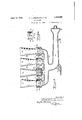
Au LINDEMANN ET AL GAS HEATER Fil ed Feb. 21.
1928 2 Sheets-Sheet (7' awuewtoz W April 12, 1932.
A. J. LINDEMANN ET AL GAS HEATER Filed Feb. 21, 1928 2 Sheets-Sheet Patented Apr. 12, 1932 UNITED STATES ATENT OFFICE ALBERT J. LINDEMANN AND WALTER G. LINDEMANN, OF MILWAUKEE, WISCONSIN,
ASSIGNORS TO A. J. LINDEMANN & HOVERSON' COMPANY, OF MILWAUKEE, WIS- CONSIN, A CORPORATION OF WISCONSIN GAS HEATER Application filed February 21, 1928. Serial No. 255,881.
The resent improvements relate in gen having a novel arrangement of parts cooperating with a radiant body, affording an improved heating unit.
' Various other ob ects and advantages, of 16 the present improvements, will be apparent upon reference to the accompanying drawings, in which Fig. 1 is a sectional view of a parlor heater illustrating the improved construction;
Fig. 2 is a plan view taken on line 22 of Fig. l;
Fig. 3 is a sectional view of the burner or heating unit; and
Fig. f is a side elevation of the removable 25 cup or pocket. p
Referring to Fig. 1, the parlor heater 11- lustrating the improved construction comprises an outer upright casing 5 having the front and rear plates 6 and 7 respectively, 30 and sides 8. Said casing is provided with a head 9 having anopening 10 to the atmosphere, said head being of any desired form, pleasing to the eye, for presenting'a neat appearance. The casing 5 has an open bottom 85 and is supported on a perimetric frame havin legs 11. v guitably mounted within caslng 5, is a drum 12 providing a combustion chamber 12 as hereinafter described. Said drum is somewhat smaller in cross-section than casing 5, and is concentrically mounted therein,
- said casing and drum having common longitudinal axes. In thus disposing the drum 12 in spaced relation to the casing 5, an annular 4 or peripheral air duct or flue 13 is defined.
As illustrated, said flue has free communication with the atmosphere at the base of the casing indicated at 14, and affords an air conduit or flue for the passage of air from the base to the top of the structure, between the upright walls of the casing and drum. Although the drum 12 terminates just beneath the casing head 9, the flue l3, continues, in effect, to the opening 10, its limits in this region being defined by the head 9.
'The drum 12 has a closed top 15 but is provided with an opening 16 at the upper rear side thereof for the discharge of hot air, combustion gases, etc., a combustion flue 17 being sealed to said opening, bridging air duct 13 and passing through casing 5 to the atmosphere, as for example, a chimney. The base of said drum is closed with the exception of apertures 18 therein for admitting secondary air to the fuel burners.
Positioned eccentrically of the drum, and spaced from the walls thereof, is a plurality of air ducts or flues 19, which extend longitudnally through the drum from top to bottom, communication with the atmosphere being afforded, atthe bottom through openings 20, and at the top through space 9 and opening 10. Although any number of such flues may be provided, three are preferable for accomplishing most eflicient results.
Suitably mounted in the lower fore portion of the combustion chamber 12 is the burner or heater unit 21. While the heated air and combustion products ascend from said unit through the chamber 12 toflue 17 heat is also'transmitted to the surrounding atmosphere, by radiation from the refractory elements 22 of the burners, through opening 23 of the drum 12 and grid 24 in casing 5. The grid 24 may be open, or provided with mica as desired.
' It will be noted that when the burners are lighted, convection currents will be set up in flues 13 and 19, cool air entering at the bottom thereof, being heated by the gases of the combustion chamber 12 as the air ascends and leaving the casing through top opening 10. In order that a maximum amount of heat may be transferred to the air ducts, means are provided for compelling the combustion gases and hot air in chamber 12 to follow a zigzag course in their travel to flue 17.. Accordingly a deflector plate 25 and laterally extending bafiles or deflectors 26 and 27 are positioned within the drum 12 between openings 23 and 16. These baflles are secured, in spaced relation, to the walls of the drum, and embrace or encircle the air ducts 19: As illustrated the baffles 26 extend from the front wall of the drum and terminate short of the rear wall thereof, likewise baffles 27 project from the rear wall and terminate short of the front wall. This staggered arrangement affords a relatively long passage compelling the hot products to follow a to'rtuous path through chamber 12. Therefore, before the gases may ultimately be dis charged, they alternately come in contact with the drum walls and walls of air ducts 19. With every such contact, heat is conducted through the wallsto the air in ducts 13 and 19, it being noted that the gases completely encircle the ducts 19 several times in their travel. The abrupt turns in the tortuous path are of distinct advantage, since the gases exert a scouring action on the drum Walls at these points thereby freeing same of deposits and maintaining a clear passage.
The present improvements accordingly provide a plurality of upright air circulation ducts housed within one another, one of which (defined by drum 12) affords a combustion chamber 12. A maximum transfer of heat is obtained by providing a hot air flue l3 surrounding the chamber 12', and by disposing flues 19 within said chamber. Furthermore the proximity of flues 19 tothe burners and the arrangement of deflector 25 insure an extens ve transfer of heat directly from the unit 21 to ducts l9.
Referring more particularly to Figs. 3 and 4, the heating unit 21 comprises a mixing chamber 30 having the usual inlet for gas and primary air, and securing means or supports 31 for mounting in the combustion chamber 12. Cast integrally with the mixing chamber are a plurality of upstanding sleeves 32 having preferably cylindrical walls. As illustrated, said sleeves have contracted necks 33 at their point of union with the chamber 30. The number of sleeves provided on the chamber may be varied as desired. As the burners are identical, the structure .of one only will be described.
The sleeve or cylindrical body 32 aflords, with its contracted neck, a pocket or cup in which the remaining elements of the burner are supported. A second cup or inverted dome-shaped member 34 is supported within said cup 32. This cup 34, see Fig. 4, has a cylindrical wall of substantially the same Three or more such ribs may be provided in spaced relation about the periphery of the cup.
By referring to Fig. 3 the position of cup 34 in cup 32 will be observed. When the cup 34 is placed in position in pocket or cup 32, the supporting ends 37 of ribs 36 contact the contracted neck 33 thereof, the relation and proportion ofparts being such that the inner cup is spaced from the outer cup thereby forming an annular jet orifice for the gaseous mixture while the bottom or dome of cup 34 is suitably spaced from neck 33. It will be noted that when the parts are thus assembled, the upstanding walls of the cups are flush at their ends, but the ribs 36 terminate short of the plane of said ends.- These ribs serve the dual function of spacers for the cups, as well as supports, in co-operation with supporting neck 33, for the inner cup .or pocket.
Mounted in the inner cupor pocket 34 is a refractory member or ceramic 22,,having a solidb-ase 38, of cylindrical form and a hollow frusto-eonical body 39. The element 22 is so proportioned that its base 38 has a nice fit within cup 34, whereby the element will be closely fitted in cup 34, both these elements are readily removable for facilitating clean ing and replacement.
Assuming the gas cock for the mixing chamber 30 to be on, the gaseous mixture reaches the cup 32 from chamber 30 through inlet 40 of contracted neck 33. The bottom of cup 34 now functions to deflect or direct the gases to the annular chamber between the cups whence it ascends to the annular orifice 41 where it is ignited. Since ribs 36 do. not extend the entire height of the cups, the mixture spreads throughout the chamber 41 affording an annular gaseous ring which burns with an annular flame with the ceramic axially thereof.
As illustrated, the burner parts are so proportioned and arranged that burning of the mixture occurs neither beneath or within the refractory element 22. In the present construction the gas is burned on the outside of the radiant and therefore permits a free supply of secondary air about the burner, thus eliminating the possibility of producing obnoxious odors, carbon monoxide, etc.
Furthermore the firm and accurate setting of p the ceramic with respect to the inner cup, and also a similar setting of said cup with respect to the pocket or outer cup 32, insures a complete annular flame, the ceramic by its form and disposition materially contributing thereto. A hollow refractory element of the type depicted, surrounded by a cylindrical sheet of flame, is found to increase radiation of the heat and therefore provides a feature of economy in use in the improved heater set forth.
Although the improvements have been i1; lustrated in connecti on with a casing of rectangular design, it is apparent'that same may be varied as desired without departing from the scope of the invention.
Various other embodiments and modifica tions within the scope of the mprovements herein 'set forth may be apparent to those skilled in the art.
We claim:
1. A burner construction comprising a.
mixing chamber terminating in a cup shaped wall, a fuel inlet in the base thereof, acup mounted within and coextensive with said wall and defining burner orifices therewith, said cup having a pointed bottom extending to-said inlet, and a refractory body supported in said cup. 2. A burner for gaseous fuels comprising a cup having an inlet at its base, a second cup telescopic therein and having a pointed base extending to said inlet, means for spacing said cups and a refractory body supporte by said second cup.
3. A burner construction comprising a cylindrical body having a contracted lower portion, a cup supported in said body and spaced therefrom thereby forming an annular jet orifice, said cup be1n coextensive with the contracted portion for efining a fuel inj let for said orifice, and a ceramic supported in said cup.
4. A burner construction comprising a body having upstanding contiguous walls,
inlet means for said body for supplying fuel thereto, a receptacle adapted to hold a refractory element supported within said body and spaced therefrom, said receptacle having a pointed base directed toward said inlet.
5. A gas-burner comprising a cup having a fuel inlet, an inverted dome-shaped member fitted within said cup having its bowl positioned axiall of said inlet and providing a deflector there or, the baseof said member being flush with the end of said cup, means for spacing said member and on and a refractory element su ported by sald member.
Witness our han s this 16th day of February, 1928 at the city of Milwaukee, in the county of Milwaukee, State of Wisconsin. ALBERT ,J. LINDEMANN.
WALTER C. LINDEMANN.
Priority Applications (1)
| Application Number | Priority Date | Filing Date | Title |
|---|---|---|---|
| US255881A US1853690A (en) | 1928-02-21 | 1928-02-21 | Gas heater |
Applications Claiming Priority (1)
| Application Number | Priority Date | Filing Date | Title |
|---|---|---|---|
| US255881A US1853690A (en) | 1928-02-21 | 1928-02-21 | Gas heater |
Publications (1)
| Publication Number | Publication Date |
|---|---|
| US1853690A true US1853690A (en) | 1932-04-12 |
Family
ID=22970242
Family Applications (1)
| Application Number | Title | Priority Date | Filing Date |
|---|---|---|---|
| US255881A Expired - Lifetime US1853690A (en) | 1928-02-21 | 1928-02-21 | Gas heater |
Country Status (1)
| Country | Link |
|---|---|
| US (1) | US1853690A (en) |
Cited By (1)
| Publication number | Priority date | Publication date | Assignee | Title |
|---|---|---|---|---|
| US3225815A (en) * | 1962-06-15 | 1965-12-28 | Hupp Corp | Gas burners |
-
1928
- 1928-02-21 US US255881A patent/US1853690A/en not_active Expired - Lifetime
Cited By (1)
| Publication number | Priority date | Publication date | Assignee | Title |
|---|---|---|---|---|
| US3225815A (en) * | 1962-06-15 | 1965-12-28 | Hupp Corp | Gas burners |
Similar Documents
| Publication | Publication Date | Title |
|---|---|---|
| US2183836A (en) | Fluid fuel burner | |
| US3627462A (en) | Top gas burner for a stove | |
| US2311570A (en) | Stove | |
| US1216848A (en) | Heater. | |
| US3190283A (en) | Compact instantaneous water heater | |
| US1869939A (en) | Heating apparatus | |
| US3162237A (en) | Pressurized gas burner | |
| US1853690A (en) | Gas heater | |
| US2262922A (en) | Oil burning heater | |
| US1532612A (en) | Gas burner | |
| US1887330A (en) | Gas burner | |
| US2537966A (en) | Pot type oil burner with pilot chamber | |
| US1962756A (en) | Gas burner | |
| US1735618A (en) | Burner unit for gas heating apparatus | |
| US1735654A (en) | Gas stove or range | |
| US1732876A (en) | Furnace | |
| US2257396A (en) | Top structure for cookstoves | |
| US2602495A (en) | Pilot for vaporizing burners | |
| US2452924A (en) | Pot burner having segmental air directing means | |
| US1410708A (en) | Furnace | |
| US2483978A (en) | Tray type oil burner | |
| US1808866A (en) | Gas oven construction | |
| US2700417A (en) | Recirculating vaporizing liquid fuel burner | |
| US1703115A (en) | Fuel-combustion chamber for gas burners | |
| US2198511A (en) | Liquid fuel burner |