US1853619A - Truck for railway cars - Google Patents
Truck for railway cars Download PDFInfo
- Publication number
- US1853619A US1853619A US326568A US32656828A US1853619A US 1853619 A US1853619 A US 1853619A US 326568 A US326568 A US 326568A US 32656828 A US32656828 A US 32656828A US 1853619 A US1853619 A US 1853619A
- Authority
- US
- United States
- Prior art keywords
- bolster
- side frame
- lugs
- cap
- spring
- Prior art date
- Legal status (The legal status is an assumption and is not a legal conclusion. Google has not performed a legal analysis and makes no representation as to the accuracy of the status listed.)
- Expired - Lifetime
Links
- 230000000284 resting effect Effects 0.000 description 4
- 238000010276 construction Methods 0.000 description 3
- 241000157282 Aesculus Species 0.000 description 1
- 235000012571 Ficus glomerata Nutrition 0.000 description 1
- 240000000365 Ficus racemosa Species 0.000 description 1
- 241001275902 Parabramis pekinensis Species 0.000 description 1
- 229910000831 Steel Inorganic materials 0.000 description 1
- 235000015125 Sterculia urens Nutrition 0.000 description 1
- 230000000712 assembly Effects 0.000 description 1
- 238000000429 assembly Methods 0.000 description 1
- 238000005266 casting Methods 0.000 description 1
- 235000010181 horse chestnut Nutrition 0.000 description 1
- JTJMJGYZQZDUJJ-UHFFFAOYSA-N phencyclidine Chemical compound C1CCCCN1C1(C=2C=CC=CC=2)CCCCC1 JTJMJGYZQZDUJJ-UHFFFAOYSA-N 0.000 description 1
- 238000005096 rolling process Methods 0.000 description 1
- 230000013707 sensory perception of sound Effects 0.000 description 1
- 239000010959 steel Substances 0.000 description 1
Images
Classifications
-
- B—PERFORMING OPERATIONS; TRANSPORTING
- B61—RAILWAYS
- B61F—RAIL VEHICLE SUSPENSIONS, e.g. UNDERFRAMES, BOGIES OR ARRANGEMENTS OF WHEEL AXLES; RAIL VEHICLES FOR USE ON TRACKS OF DIFFERENT WIDTH; PREVENTING DERAILING OF RAIL VEHICLES; WHEEL GUARDS, OBSTRUCTION REMOVERS OR THE LIKE FOR RAIL VEHICLES
- B61F5/00—Constructional details of bogies; Connections between bogies and vehicle underframes; Arrangements or devices for adjusting or allowing self-adjustment of wheel axles or bogies when rounding curves
- B61F5/02—Arrangements permitting limited transverse relative movements between vehicle underframe or bolster and bogie; Connections between underframes and bogies
- B61F5/04—Bolster supports or mountings
- B61F5/12—Bolster supports or mountings incorporating dampers
Definitions
- This invention relates to railway rolling stock, and especially to a novel truck for railway cars.
- Such trucks usually include pairs, of wheels mounted on transverse axles having projecting ends which fit into hearings in side frames that support the spring assemblies on which the bolster rests.
- Some of such trucks are known as lateral motion trucks, for
- the bolster may shift laterally relatively to the side frames, and on the other hand, the side frames may shlft
- Our invention is directed particularly to trucks of this character, and the primary object 1s to furnish a structure which will facilitate assembly, and dismantling, and permit espeor replacement of the wheels.
- I A further object is to provide a truck 0 the lateral motion type, in which either one or both of the side frames may be expeditious- 7 1y removed after the spring planks, springs, spring caps, bolster, and the attached brake parts, have been elevated as a unit to a predetermined height relatively to one or both of the side frames.
- a still further object is to furnish a lateral motion truck in which certain parts are provided with projecting portions designed to enter guideways in other parts, and to interlock the parts together, when the spring planks ,are lowered relatively to the side frames.
- Another'object is to provide a truck of this type, in which the side frames have horizontally disposed'guides to allow oppositely extending projections on the bolster to pass' through the side frames, and to them be lowered with the bolster relatively tothe side frames for interlocking the bolster and side frames.
- Another object is to furnish spring caps having opposite projections designed to enter recesses in the side frames, which communicate with vertical guides, whereby after the projections ofa spring cap have been introduced through the recesses into the guides and lowered, the guides will interlock with the projections to prevent excess lateral "spring caps.
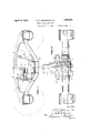
- FIG. 1 is an elevation of one side of the truck, with certain parts broken away, and
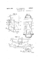
- Fig. 2 is a plan View partly in horizontal section, of one side of the truck and with the frame isto be attached to the end of the bol-' ster, or to be detached therefrom.
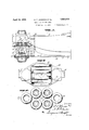
- Fig. 7 is a vertical sectional view of one of the side frames, taken on line 77 in Fig. '1, and with the spring planking, springs, spring cap and bolster removedr
- Fig. 8 is an end view of the bolster.
- Fig 9 is an-elevation of one of the improved In the drawings, ilfdesignates a bolster which may be of any desired construction, so long as it is provided at its ends with oppositely extending lugs 2, which may pass through guides 3 provided in the side frames 4. It will be obvious that instead of placing the lugs on the bolster and the guides on the side frames, these'parts might be reversed,
- this construction is to permit the side frames to be moved on to the ends of the bolster, when the latter is in an elevated position. At such times, the lugs will be aligned with the guides 3, and when the side frames are moved laterally, the lugs will. readily pass along the guides. After and the lugs might goon the side frames the ends of the bolster have been passed through the main openings 5 of the side frames, it is apparent that when the bolster is lowered, the lugs will be in position to strike projecting extensions 6 on the side frames, and this will limit the lateral movement of the bolster.
- Each end of the bolster is supported by a plurality of rollers 7, that roll in inverted grooves 8 on the underside of the bolster, and in similar grooves 9 on a spring cap 10. These rollers allow the lateral motion heretofore mentioned.
- Each of the spring caps is provided at its ends with lugs 11, preferablyforming' part of the casting from which the cap is made, and these lugs are designed to enter horizontal grooves or gates 12 arranged on the inner sidesof the side frames, (see Figs. 9r, 6 and 7
- These grooves or gates communicate with vertical grooves 13, formed in the columns 1a of the side frames, and the opposite walls 15 of each guide 13 form stops for limiting the lateral movement of the cap after the lugs 11 of the latter have been introduced through the gates 12 into the vertical guides.
- the spring cap 10 rests on springs 17, preferably of coiled type, and the end springs of each series are at a slightly higher elevation than the other springs of the series, and enter cavities 18 formed in the bottom of the extensions 19 of the cap.
- each set of springs rests on a spring plank 21, which is" specially shaped to engage With and rest on the yoke 20 of the side frame, and from this plank, but integral with it, rises brackets 22 for supporting the brake rigging.
- the side frames are provided with boxes 23 to receive the ends of the wheel axles.
- either side frame may be detached by simply moving the same horizontally in a direction away from the end of the bolster.
- the side frame may be replaced by a similar movement, but in the opposite direction, and of course when the j aeks are lowered, the lugs 2 will overlap the extensions 6 of the frame, and the lugs 11 of the spring cap will again engage the guideways' 13.
- a car truck including a bolster memher and a side frame member, said side frame member being adapted to be moved on or oil one end of the bolster member, one of said members having projecting lugs, and the other member having guides at its top portion to permit the passage of the lugs when the side frame member is placed on or taken off the bols er member, rollers supporting an end of the bolster member, a spring cap supporting the rollers, and springs supporting the spring caps and carried by the side frame member.
- a car truck including a bolster member and a side frame member, the side frame member having an opening through which an end of the bolster member may project and move upwardly and downwardly, one of said men'ibers havii'ig projections and the other having guideways at its top portion to accommodate said projections, for permitting the side frame member to be moved on or off.
- a car truck including a bolster and a side frame, the side frame having an opening into which one end ofthe bolster may project and move upwardly and downwardly, grooves in the side frame, oppositely projecting lugs on the bolster designed to occupy said grooves wnen the side frame is moved on or ofi the end of the bolster, and extension walls on the side frame projecting toward each other, below said grooves, and overlapping said lugs to prevent disengagement of the bolster with the side frame when the lugs are out of alignment with said grooves, said lugs being spaced from said extension walls, and the spaces being unobstructed to allow lateral shifting of the bolster.
- a side frame member having an opening therein, a bolster having one of its ends extending into said opening, a spring cap member on which the bolster end rests, one of said members being'provided with oppositely extending lugs, and the other member having angular grooves to receive said lugs, said members being disconnectible from one another when the spring seat member is in elevated position.
- a car truck including a side frame having an opening therein, a bolster having'one of its ends extending into said opening, a spring cap in the opening on which the bolster end rests, angular grooves provided in opposite side walls of the side frame, and oppositely extending lugs on the spring cap engaging said grooves, said grooves normally preventing the spring cap from detaching from the side frame, but permitting quick detachment when the cap and side frame are in certain relative positions.
- a car truck including a side frame member, a bolster member, one of said members having guides and the other having lugs slidable in said guides, a spring cap member on which the bolster end rests, other guides on one of said members, and additional lugs on another one of said members to permit the cap member to be interlocked with the side frame member.
- a car truck including a side frame having an opening therein, a bolster having one of its ends extending into said opening, guides on the side frame, lugs on the bolster adapted to slide through said guides for in terlocking the bolster to the side frame, a spring cap, rollers interposed between the bolster and cap and permitting lateral motion of the bolster,'angular guides on the side frame, and lugs on the cap engageable with the angular guides, said angular guides permitting quick detachment of the spring cap from the side frame.
- a car truck including a spring plank, springs supported by the plank, a spring cap resting on the springs, rollers carried by the cap, a bolster having one of its ends resting on said rollers, said parts capable of moving up and down as a unit, a side frame having an opening into which said parts extend, and interlocking elements on the bolster, cap and side frame permitting detachment of the side frame by a horizontal movement of the latter away from the bolster When said unit is in a certain position relatively to the side frame.
- a car truck including a wheel supported side frame having an opening therein, a spring plank in the opening and resting on said side frame, springs carried by the plank,
- a spring cap supported by the springs, said side frame having oppositely disposed an-. gular grooves, and said cap having lugs extending into said grooves, rollers'supported by the cap, a bolster having one of its ends extending into the opening of the side frame and resting on said rollers, other grooves provided in the side frame, and lugs on the bolster adapted to move through the last means on the cap, bolster and side frame for normally preventing the unit from moving laterallyto an undue extent relatively to the side frame, said means permitting quick detachment ofthe side frame when r the unit has been elevated to a certain position relatively to the side frame.
Landscapes
- Engineering & Computer Science (AREA)
- Mechanical Engineering (AREA)
- Body Structure For Vehicles (AREA)
Description
April 12, 1932. e. T. JOHNSON ET AL TRUCK FOR RAILWAY CARS Filed Dec. 17, 1928 3 Sheets-Sheet 1 April 12, 1932. G. T. JOHNSON ET AL TRUCK FOR RAILWAY CARS Filed Dec. 17, 1928 3 Sheets-Sheet 2 April 12,1932. G JOHNQQN ET AL 1,853,619
TRUCK FOR RAILWAY CARS Filed De .-l7, 1928 s Sheets-Sheet 3 "cially, quick removal Patented Apr. 12, 1932 i" umran STATES PATENT OFFICE f GEORGE T. JOHNSON AND .ABTHUR H. FILANDER, OF COLUMBUS, OHIO, ASSIGNOR-S TO THE BUCKEYE STEEL CASTINGSCOIYEPANY, 0F COLUMBUS, OHIO TRUCK FOB RAiLwAY cans I Application filed December 17, 1928. Serial No. 326,568,
This invention relates to railway rolling stock, and especially to a novel truck for railway cars. y
7 Such trucks usually include pairs, of wheels mounted on transverse axles having projecting ends which fit into hearings in side frames that support the spring assemblies on which the bolster rests. Some of such trucks are known as lateral motion trucks, for
in those structures, the bolster may shift laterally relatively to the side frames, and on the other hand, the side frames may shlft Our invention is directed particularly to trucks of this character, and the primary object 1s to furnish a structure which will facilitate assembly, and dismantling, and permit espeor replacement of the wheels. I A further object is to provide a truck 0 the lateral motion type, in which either one or both of the side frames may be expeditious- 7 1y removed after the spring planks, springs, spring caps, bolster, and the attached brake parts, have been elevated as a unit to a predetermined height relatively to one or both of the side frames.
A still further object is to furnish a lateral motion truck in which certain parts are provided with projecting portions designed to enter guideways in other parts, and to interlock the parts together, when the spring planks ,are lowered relatively to the side frames. V
Another'object is to provide a truck of this type, in which the side frames have horizontally disposed'guides to allow oppositely extending projections on the bolster to pass' through the side frames, and to them be lowered with the bolster relatively tothe side frames for interlocking the bolster and side frames. 7
Another object is to furnish spring caps having opposite projections designed to enter recesses in the side frames, which communicate with vertical guides, whereby after the projections ofa spring cap have been introduced through the recesses into the guides and lowered, the guides will interlock with the projections to prevent excess lateral "spring caps.
movement of the same while readily permitting the cap to move verticaly with the springs. 1 v
The invention will now be described in detail, in connection with the accompanying drawings, in which Fig; 1 is an elevation of one side of the truck, with certain parts broken away, and
other parts in dotted and dashlines to facilitate illustration. I
Fig. 2 is a plan View partly in horizontal section, of one side of the truck and with the frame isto be attached to the end of the bol-' ster, or to be detached therefrom.
Fig. 7 is a vertical sectional view of one of the side frames, taken on line 77 in Fig. '1, and with the spring planking, springs, spring cap and bolster removedr Fig. 8 is an end view of the bolster. Fig 9 is an-elevation of one of the improved In the drawings, ilfdesignates a bolster which may be of any desired construction, so long as it is provided at its ends with oppositely extending lugs 2, which may pass through guides 3 provided in the side frames 4. It will be obvious that instead of placing the lugs on the bolster and the guides on the side frames, these'parts might be reversed,
and the guideways be placed in the bolster.
' The purpose of this construction is to permit the side frames to be moved on to the ends of the bolster, when the latter is in an elevated position. At such times, the lugs will be aligned with the guides 3, and when the side frames are moved laterally, the lugs will. readily pass along the guides. After and the lugs might goon the side frames the ends of the bolster have been passed through the main openings 5 of the side frames, it is apparent that when the bolster is lowered, the lugs will be in position to strike projecting extensions 6 on the side frames, and this will limit the lateral movement of the bolster.
Each end of the bolster is supported by a plurality of rollers 7, that roll in inverted grooves 8 on the underside of the bolster, and in similar grooves 9 on a spring cap 10. These rollers allow the lateral motion heretofore mentioned.
Each of the spring caps, as best shown in Figs. 1, 6 and 9, is provided at its ends with lugs 11, preferablyforming' part of the casting from which the cap is made, and these lugs are designed to enter horizontal grooves or gates 12 arranged on the inner sidesof the side frames, (see Figs. 9r, 6 and 7 These grooves or gates communicate with vertical grooves 13, formed in the columns 1a of the side frames, and the opposite walls 15 of each guide 13 form stops for limiting the lateral movement of the cap after the lugs 11 of the latter have been introduced through the gates 12 into the vertical guides.
It will be observed at this point that as the end of the bolster rests on the rollers 7, which are in turn carried by the spring cap, that at the time the lugs 11 of the cap are in position to pass through the gates 12, the lugs 2 of the bolster will also be in position to travel in the grooves 3', as best shown in Fig. 6. Of "course, the Walls 16 of the columns 14: opposite the gates 12 form obstructions to prevent the lugs 11 from being passed entirely through the side frame from the inner side to the outer side of the latter.
As is customary in lateral motion trucks, the spring cap 10 rests on springs 17, preferably of coiled type, and the end springs of each series are at a slightly higher elevation than the other springs of the series, and enter cavities 18 formed in the bottom of the extensions 19 of the cap.
In the present invention, each set of springs rests on a spring plank 21, which is" specially shaped to engage With and rest on the yoke 20 of the side frame, and from this plank, but integral with it, rises brackets 22 for supporting the brake rigging.
The side frames, as is usual, are provided with boxes 23 to receive the ends of the wheel axles.
From the above it will be clear to those skilled in the art that when aoks are placed under the spring plank bar 21, and the latter is raised, its ends will be lifted off the 'yokes 20 of the side frames, and at the same time, the lugs 11 of the spring caps will rise to positions in alignment with the gates 12. Obviously, as the spring caps rise, they will lift the bolster 1 and its lugs 2 will be brought into alignment with the groox' es-i).
Now if the usual brasses and Wedges are removed, either side frame may be detached by simply moving the same horizontally in a direction away from the end of the bolster.
On the other hand, the side frame may be replaced by a similar movement, but in the opposite direction, and of course when the j aeks are lowered, the lugs 2 will overlap the extensions 6 of the frame, and the lugs 11 of the spring cap will again engage the guideways' 13.
(l hen the parts are properly assembled, it will be recognized that the spring caps may riseand fall with the bolster, and the Walls 15 of the grooves 13 will prevent undue lateral movement of these caps, and at the same time, the bolster may shift laterally on the rollers 7, but it will be prevented from shiftto-too great an extent by the lugs 2 striking the extensions 6.
From the foregoing, it is believed that the construction, operation and advantages of the invention may be readily understood. by those skilled in the art, and it is apparent hat changes be made in the details disclosed, without departing from the scope of the annexed claims What is claimed and desired to be secured by Letters Patent is:
1. A car truck including a bolster memher and a side frame member, said side frame member being adapted to be moved on or oil one end of the bolster member, one of said members having projecting lugs, and the other member having guides at its top portion to permit the passage of the lugs when the side frame member is placed on or taken off the bols er member, rollers supporting an end of the bolster member, a spring cap supporting the rollers, and springs supporting the spring caps and carried by the side frame member.
2. A car truck including a bolster member and a side frame member, the side frame member having an opening through which an end of the bolster member may project and move upwardly and downwardly, one of said men'ibers havii'ig projections and the other having guideways at its top portion to accommodate said projections, for permitting the side frame member to be moved on or off. one end of the bolster member, and resilient supporting means for an end of the bolster member, including rollers to allow the bolster member to shift laterally relatively to the side frame member.
3. A car truck including a bolster and a side frame, the side frame having an opening into which one end ofthe bolster may project and move upwardly and downwardly, grooves in the side frame, oppositely projecting lugs on the bolster designed to occupy said grooves wnen the side frame is moved on or ofi the end of the bolster, and extension walls on the side frame projecting toward each other, below said grooves, and overlapping said lugs to prevent disengagement of the bolster with the side frame when the lugs are out of alignment with said grooves, said lugs being spaced from said extension walls, and the spaces being unobstructed to allow lateral shifting of the bolster.
4. In a car truck, a side frame member having an opening therein, a bolster having one of its ends extending into said opening, a spring cap member on which the bolster end rests, one of said members being'provided with oppositely extending lugs, and the other member having angular grooves to receive said lugs, said members being disconnectible from one another whenthe spring seat member is in elevated position.
5. A car truck including a side frame having an opening therein, a bolster having'one of its ends extending into said opening, a spring cap in the opening on which the bolster end rests, angular grooves provided in opposite side walls of the side frame, and oppositely extending lugs on the spring cap engaging said grooves, said grooves normally preventing the spring cap from detaching from the side frame, but permitting quick detachment when the cap and side frame are in certain relative positions.
6. A car truck including a side frame member, a bolster member, one of said members having guides and the other having lugs slidable in said guides, a spring cap member on which the bolster end rests, other guides on one of said members, and additional lugs on another one of said members to permit the cap member to be interlocked with the side frame member.
7. A car truck including a side frame having an opening therein, a bolster having one of its ends extending into said opening, guides on the side frame, lugs on the bolster adapted to slide through said guides for in terlocking the bolster to the side frame, a spring cap, rollers interposed between the bolster and cap and permitting lateral motion of the bolster,'angular guides on the side frame, and lugs on the cap engageable with the angular guides, said angular guides permitting quick detachment of the spring cap from the side frame.
8. A car truck including a spring plank, springs supported by the plank, a spring cap resting on the springs, rollers carried by the cap, a bolster having one of its ends resting on said rollers, said parts capable of moving up and down as a unit, a side frame having an opening into which said parts extend, and interlocking elements on the bolster, cap and side frame permitting detachment of the side frame by a horizontal movement of the latter away from the bolster When said unit is in a certain position relatively to the side frame.
9. A car truck including a wheel supported side frame having an opening therein, a spring plank in the opening and resting on said side frame, springs carried by the plank,
a spring cap supported by the springs, said side frame having oppositely disposed an-. gular grooves, and said cap having lugs extending into said grooves, rollers'supported by the cap, a bolster having one of its ends extending into the opening of the side frame and resting on said rollers, other grooves provided in the side frame, and lugs on the bolster adapted to move through the last means on the cap, bolster and side frame for normally preventing the unit from moving laterallyto an undue extent relatively to the side frame, said means permitting quick detachment ofthe side frame when r the unit has been elevated to a certain position relatively to the side frame.
In testimonywhereof, we have signed this specification.
GEORGE T. JOHNSON. ARTHUR H. FILANDER.
Priority Applications (1)
| Application Number | Priority Date | Filing Date | Title |
|---|---|---|---|
| US326568A US1853619A (en) | 1928-12-17 | 1928-12-17 | Truck for railway cars |
Applications Claiming Priority (1)
| Application Number | Priority Date | Filing Date | Title |
|---|---|---|---|
| US326568A US1853619A (en) | 1928-12-17 | 1928-12-17 | Truck for railway cars |
Publications (1)
| Publication Number | Publication Date |
|---|---|
| US1853619A true US1853619A (en) | 1932-04-12 |
Family
ID=23272775
Family Applications (1)
| Application Number | Title | Priority Date | Filing Date |
|---|---|---|---|
| US326568A Expired - Lifetime US1853619A (en) | 1928-12-17 | 1928-12-17 | Truck for railway cars |
Country Status (1)
| Country | Link |
|---|---|
| US (1) | US1853619A (en) |
-
1928
- 1928-12-17 US US326568A patent/US1853619A/en not_active Expired - Lifetime
Similar Documents
| Publication | Publication Date | Title |
|---|---|---|
| US2031777A (en) | Car truck | |
| US1853619A (en) | Truck for railway cars | |
| US2104840A (en) | Resilient side bearing assembly | |
| US1936645A (en) | Car truck | |
| US2108378A (en) | Car truck construction | |
| US1745665A (en) | Truck for railroad cars | |
| US1973664A (en) | Car truck | |
| US1952378A (en) | Car truck | |
| US2063739A (en) | Truck | |
| US2055278A (en) | Railway truck | |
| US2594079A (en) | Inboard railway truck | |
| US1650173A (en) | Car truck | |
| US1793574A (en) | Car truck | |
| US1783737A (en) | Car truck | |
| US1703058A (en) | Spring support | |
| US1629476A (en) | Spring support | |
| US2011190A (en) | Railway truck | |
| US1952295A (en) | Car truck | |
| US1827854A (en) | Railway rolling stock | |
| US2006686A (en) | Coupler carrier mechanism | |
| US2460696A (en) | Railway car truck side frame | |
| US1434830A (en) | Truck side-frame construction | |
| US1891583A (en) | Truck bolster | |
| US1886417A (en) | Self-centering coupler carrier | |
| US1830512A (en) | Car truck |