US1853545A - Dam - Google Patents
Dam Download PDFInfo
- Publication number
- US1853545A US1853545A US448506A US44850630A US1853545A US 1853545 A US1853545 A US 1853545A US 448506 A US448506 A US 448506A US 44850630 A US44850630 A US 44850630A US 1853545 A US1853545 A US 1853545A
- Authority
- US
- United States
- Prior art keywords
- deck
- bents
- dam
- supports
- joints
- Prior art date
- Legal status (The legal status is an assumption and is not a legal conclusion. Google has not performed a legal analysis and makes no representation as to the accuracy of the status listed.)
- Expired - Lifetime
Links
Images

Classifications
-
- E—FIXED CONSTRUCTIONS
- E02—HYDRAULIC ENGINEERING; FOUNDATIONS; SOIL SHIFTING
- E02B—HYDRAULIC ENGINEERING
- E02B7/00—Barrages or weirs; Layout, construction, methods of, or devices for, making same
- E02B7/02—Fixed barrages
- E02B7/04—Dams across valleys
- E02B7/08—Wall dams
- E02B7/14—Buttress dams
Definitions
- This invention relates to a noveland improved'form of dam, the novel features ofwhich will bebest understood from the fol-- ;lowing description and the annexed drawgings, in which are shown selectedembodiments of the invention, and in which Fig. 1 is a vertical sectional View taken on a plane extending up stream and down. stream through a dam and illustrating. the
- Fig. 2 is a view on the same plane-as Fig. 1 and showingone form. which the invention may take; o
- Fig. 3 is a section'on the. line 3+3 o-f "Fig. 2;
- Figs. 4 and 5 are viewssimilar-toFig. 3, but showing different forms which the inventionmaytake;
- V Fig. 6 is a View similar to Fig. 2,.but illustrating another embodiment of, the ,inven-.
- the bents 5 are separated by joints 6, these joints being arranged approximately on surfaces parallel to thedirection'l of first principal stress atthatlocationfand,
- Each'bentf) is preferably designed so as to be laterally stablein'depend- I ently of other 'bents, and. in Fig. '3, I have shown. this as being accomplished by'makin'g the bent of U-formandhaving grooves 7 .re-' DCving keys 8 on adjoining bents.
- Thearms of the may extend'up stream, as shownin the upper and lowerb'ents of F ig: 3,"or"may extend downstream, as shown in the middle,
- V V i I Theresultthen' is a pluralityof bents sepa rated by "surfaces of *zero' shearand which nat e beneath the deck,.whic h is shown asbes.
- the inclined or curved bents not only are monolithic incharacter but may be designed to be of such proportions that their lateral stability is assured.
- Fig. 4 is shown another form which the invention may take, in this case the bents being formed of H-sections and comprising cross pieces 14 ⁇ connecting legs 15 and these legs 15 being provided with grooves and keys 7 and 8 forming the joints between adjacent bents. It is to be understood that these joints are disposed on surfaces following the directions of first principal stresses, as in Figs. 2 and 3.
- Fig. 5 is shown another form which the bents'may take. In this case they are formed 'as boxes 16 having transverse portions 17 in contact with each other. In this form the. keys and grooves have been omitted although they may be employed, if found desirable.
- Fig. 2 the joints betweenbents termiing continuous.
- Fig. 6 is shown an embodiment in which the joints 18are ex,- tended throughthe deck, as shown at 19, thus a section of the deck between consecutive joints acts as apart of the bent between these same joints.
- internal stresses in the superstructure are reduced.
- Each bent is supported by the one beneath it, while there is no tendency forthe shrinkage in one part of the deck to affect another part, beyond one of the joints 19.
- the water tightness of the joints 19 in the deck may be provided for by the use of flashing or other suitable means.
- I Preferably, I
- a dam comprising an inclined up-stream water-bearing deck and a plurality ofsupports beneath said deck and extending down stream therefrom, each of said supports being formed of a plurality of bents separated from each other by joints substantially parallel to the direction. of first principal stress.
- a dam comprisingan incllned up-stream water-bearing deck and a plurality of supports beneath said deck and extending down stream therefrom, each of said supports being formed of a plurality of bents extending from the deck to foundation material and each constructed to transmit its load from the deck to the foundation independently of the other bents.
- a dam comprising an inclined up-stream water-bearing dec'k'and a plurality of supports beneath said deck and extending down stream therefrom, each of said supports being formed of a plurality of bents having their upper ends substantially normal to the deck and their lower ends substantially asymptotic to thedown-stream face of thedam.
- a dam comprising an inclined up -stream water-bearing deckand a plurality of sup-, ports beneath sai-ddeck and extending down stream therefrom, each'of saidsupports com prising bents disposed substantiallyparallel to the 'direction of first principal stress.
- a dam comprising an inclined up-stream water-bearing deck and a plurality of supports beneath said deck and extending down stream therefrom,each of said supports com-:
- a dam comprising an inclined lip-stream Water-bearing deck and a plurality of supports beneath said deck and extending down stream therefrom, each of said supports comprising a plurality of separate bents separated from each other by curved surfaces substantially normal to the deck and asymptotic to the down-stream face of the dam.
- a dam comprising an inclined up-stream Water-bearing deck and a plurality of supports beneath said deck and extending down stream therefrom, each of said supports comprising a plurality of separate bents separated from each other by curved surfaces substantially normal to the deck and asymptotic to the down-stream face of the dam, and keyed connections between adjacent bents permitting relative longitudinal movement but resisting relative lateral movement therebetween.
- a dam comprising an inclined up-stream Water-bearing deck and a plurality of supports beneath said deck and'extending down stream therefrom, each of said supports being formed of a plurality of bents separated from each other by joints substantially parallel to the direction of first principal stress, and means resisting relative movement between said bents along said oints.
- a dam comprising an inclined up-stream water-bearing deck and a plurality of supports beneath said deck and extending down stream therefrom, each of said supports being formed of a plurality of bents separated from each other by joints substantially parallel to the direction of first principal stress, and overlapping elements on adjacent bents to transmit part of any excess of load on one to the other, to prevent relative movement therebetween.
- a dam comprising an inclined upstream Water-bearing deck and a plurality of supports beneath said deck and extending down stream therefrom, each of said supports being formed of a plurality of bents separated from each other by joints substantially parallel to the direction of first principal stress and extending through said deck.
- a dam comprising an inclined upstream Water-bearing deck and a plurality of supports beneath said deck and extending down stream therefrom, each of said supports being formed of a plurality of bents separated from each other by joints substantially parallel to the direction of first principal stress and extending through said deck, and drains leading from said joints adjacent the deck.
Landscapes
- Engineering & Computer Science (AREA)
- Structural Engineering (AREA)
- General Engineering & Computer Science (AREA)
- Mechanical Engineering (AREA)
- Civil Engineering (AREA)
- Revetment (AREA)
Description
April 12, 1932.
E. H. BURROUGHS DAM 4 Sheets-Sheet l- Fi1ed April 30, 1930 p l 32. H. BURROUGHS 1,853,545
DAM
Filed April 30-, 1930 4 Sheets-Sheet 2 INVENTOR ATTORNEY 4 Sheets-Sheet 3 INVENTOR ATTORN E fis April 12, 1932. E. H. BURROUGHS DAM Filed April 30, 1930 y A. mxam.
WWZZ
April 12, 1932.
E.- H. BURROUGHS DAM Filed April 39, 1930 4 Sheets-Sheet 4 INVENTQR ATTOR Y Patented Apr. 12, 1 932 IJ ISI ITED EDGAR HTBURRQUGHS, or scA-RsnALE, NEW YORK; ASSIGNOIR. rro .AIMIBUIRSEIIST "(ION smuczrron COMPANY, 1110., or 11\TEW,Y0RK,'N. Y., A'GORPORATION or NEWIYORKF Application filed April '30,"
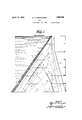
This invention relates to a noveland improved'form of dam, the novel features ofwhich will bebest understood from the fol-- ;lowing description and the annexed drawgings, in which are shown selectedembodiments of the invention, and in which Fig. 1 is a vertical sectional View taken on a plane extending up stream and down. stream through a dam and illustrating. the
io direction of certain stresses;
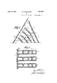
Fig. 2 is a view on the same plane-as Fig. 1 and showingone form. which the invention may take; o
Fig. 3 is a section'on the. line 3+3 o-f "Fig. 2;
Figs. 4 and 5 are viewssimilar-toFig. 3, but showing different forms which the inventionmaytake;
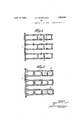
V Fig. 6 is a View similar to Fig. 2,.but illustrating another embodiment of, the ,inven-.
tion..
The type of dam covered by this application isthat inwhich there is provided an up-stream water-bearing deck 1 carried bya plurality of supports beneath it. For the purpose of illustration, Ihave shown the deck as being of the flat slab typeibut it is to be understood that when I use the term deck I intend as well to .cover other forms of 1 "water-bearing surfaces, such as arches and domes, as the invention is not limited to any particular type of :such surface. H V
In the past it has beencustomary llOQSllP- H port the deck on buttresses of generally tri- "angular form. While this. type. of. support for a deck has become practically standard, nevertheless there are certain disadvantages in its use, particularly caused by the uneven distribution of stresses. Itis to overcome these objections that I havedevised this in vention.""
Referring now to Fig. 1, I have indicated thereon certain lines 2 indicating the directions taken-by the first'principal stresses, at" spaced'intervals along thefoun'dation, or along thewater-bearingdeck: These-stresses and their directions'may becalculated. by. known methods, and it isknown that these directions are substantially normalto itlie-'-- wat'er-bearing surface and" are so curved as 1930. a Serial no. 448,506;
\ cipal stresses at spaced intervals; and it will be seen that these lines crossthe lines 4 substantially at right'an l'esi Referring. now to igs;2andf3, I have shown away in which the above principles can-be employed to obtain adanrinwhich the stresseswill be better distributed, which can be more'economically and rapidly built,
and which will have higher factors'of satay;
. than the dams of the prior art.
In Figs. 2'and 3, Ihave shownfeachsup-i I port as comprising a plurality of structural bents 5. By the-termbent Imeana'plw rality of structural elements rigidly secured together to act as one member anddesigned as a column to support a-load 'placedon' one' end thereof, The bents 5 are separated by joints 6, these joints being arranged approximately on surfaces parallel to thedirection'l of first principal stress atthatlocationfand,
therefore, on'surfaces' whichhave approxi' matelyizero shear. Each'bentf)is preferably designed so as to be laterally stablein'depend- I ently of other 'bents, and. in Fig. '3, I have shown. this as being accomplished by'makin'g the bent of U-formandhaving grooves 7 .re-' ceiving keys 8 on adjoining bents. Thearms of the may extend'up stream, as shownin the upper and lowerb'ents of F ig: 3,"or"may extend downstream, as shown in the middle,
- bent oflthis figure. The'bent 'adjacentthe face of the dam shown as closedat 9 and the bents adjacent the deck'are'slfown'aspro vided with flared portions 10 to 'form' seats ll for the slabs here shownas forming the'de cki This lip-stream portionof'thei bent will,'of course, vary'according to the ,particula'rztype of deck whichis used. Lateral stability. may
" also be'increased by theuse of fillets 12 and, 1
of course, the'transverse portions 13'forming the bottoms ofthe' Us add "greatly to this lateralf stability." a V V i I Theresultthen' is a pluralityof bents sepa rated by "surfaces of *zero' shearand which nat e beneath the deck,.whic h is shown asbes.
have to be designedto act as columnsand. I epensive bracing systems have been used, the
e ectiveness of which at best was unknown.
With this invention, however, the inclined or curved bents not only are monolithic incharacter but may be designed to be of such proportions that their lateral stability is assured.
Moreover in the priorart constructions the resultanto'f'all the loads on the dam falls some distance downstream from the center of gravity of the .dam, thus giving a higher normal pressure, onthe hOriZQIItalplane at the down-streainface or toe of the danithan at the lip-stream face or heel. With this invention, however, there is a better distribution of stressesbecause the center of gravity upon each horizontal section is drawn further down stream, or nearer the point of application of theresultant force, thus providing morenearly uniform distribution of the -pressures on ,each horizontal plane. With this construction again the span between supports may be increased, thus cutting down the number of supports for. the deck and saving a substantial amount of masonry.
While I have illustrated the dam as formed of concrete alone, it is to be understood that reinforcing steel may be employed where found necessary. I
In Fig. 4, is shown another form which the invention may take, in this case the bents being formed of H-sections and comprising cross pieces 14 {connecting legs 15 and these legs 15 being provided with grooves and keys 7 and 8 forming the joints between adjacent bents. It is to be understood that these joints are disposed on surfaces following the directions of first principal stresses, as in Figs. 2 and 3. j I I In Fig. 5, is shown another form which the bents'may take. In this case they are formed 'as boxes 16 having transverse portions 17 in contact with each other. In this form the. keys and grooves have been omitted although they may be employed, if found desirable.
In Fig. 2 the joints betweenbents termiing continuous. In Fig. 6, however, is shown an embodiment in which the joints 18are ex,- tended throughthe deck, as shown at 19, thus a section of the deck between consecutive joints acts as apart of the bent between these same joints. Bythis arrangement internal stresses in the superstructure are reduced. Each bent is supported by the one beneath it, while there is no tendency forthe shrinkage in one part of the deck to affect another part, beyond one of the joints 19.
The water tightness of the joints 19 in the deck may be provided for by the use of flashing or other suitable means. Preferably, I
provide drains 20 leading from the .joints 18 beneath the deck, to take care of anywater that may leak through the joints 19, and to prevent this water from building up a pressure between adjacent bents. w
While the -be'ntsaredesigned to act independently, and while the joints between bents are disposed on surfaces of approximately zero shear, nevertheless with varying loads a condition" may obtain in which some shear will be developed along these surfaces, although probably nota very great-amount. In order to take care of. this shear, however, Iprovide the adjacent surfaces of adjoining bentswith overlapping elements in the form of projections 21, which resist relative move-.
ment between the bents in a direction lengthwise of the joint. I
I claim: Y
1. A dam comprising an inclined up-stream water-bearing deck and a plurality ofsupports beneath said deck and extending down stream therefrom, each of said supports being formed of a plurality of bents separated from each other by joints substantially parallel to the direction. of first principal stress. 2. A dam comprisingan incllned up-stream water-bearing deck and a plurality of supports beneath said deck and extending down stream therefrom, each of said supports being formed of a plurality of bents extending from the deck to foundation material and each constructed to transmit its load from the deck to the foundation independently of the other bents.
A dam comprising an inclined up-stream water-bearing dec'k'and a plurality of supports beneath said deck and extending down stream therefrom, each of said supports being formed of a plurality of bents having their upper ends substantially normal to the deck and their lower ends substantially asymptotic to thedown-stream face of thedam.
4. A dam comprising an inclined up -stream water-bearing deckand a plurality of sup-, ports beneath sai-ddeck and extending down stream therefrom, each'of saidsupports com prising bents disposed substantiallyparallel to the 'direction of first principal stress.
5.1 A dam comprising an inclined up-stream water-bearing deck and a plurality of supports beneath said deck and extending down stream therefrom,each of said supports com-:
prising bents disposed substantially parallel to the direction of first principal stress and each constructed to transmitits load from the deck to the foundation independently of the other bents. 7 r
6. A dam comprising an inclined lip-stream Water-bearing deck and a plurality of supports beneath said deck and extending down stream therefrom, each of said supports comprising a plurality of separate bents separated from each other by curved surfaces substantially normal to the deck and asymptotic to the down-stream face of the dam.
7 A dam comprising an inclined up-stream Water-bearing deck and a plurality of supports beneath said deck and extending down stream therefrom, each of said supports comprising a plurality of separate bents separated from each other by curved surfaces substantially normal to the deck and asymptotic to the down-stream face of the dam, and keyed connections between adjacent bents permitting relative longitudinal movement but resisting relative lateral movement therebetween.
8. A dam comprising an inclined up-stream Water-bearing deck and a plurality of supports beneath said deck and'extending down stream therefrom, each of said supports being formed of a plurality of bents separated from each other by joints substantially parallel to the direction of first principal stress, and means resisting relative movement between said bents along said oints.
9. A dam comprising an inclined up-stream water-bearing deck and a plurality of supports beneath said deck and extending down stream therefrom, each of said supports being formed of a plurality of bents separated from each other by joints substantially parallel to the direction of first principal stress, and overlapping elements on adjacent bents to transmit part of any excess of load on one to the other, to prevent relative movement therebetween.
10. A dam comprising an inclined upstream Water-bearing deck and a plurality of supports beneath said deck and extending down stream therefrom, each of said supports being formed of a plurality of bents separated from each other by joints substantially parallel to the direction of first principal stress and extending through said deck.
11. A dam comprising an inclined upstream Water-bearing deck and a plurality of supports beneath said deck and extending down stream therefrom, each of said supports being formed of a plurality of bents separated from each other by joints substantially parallel to the direction of first principal stress and extending through said deck, and drains leading from said joints adjacent the deck.
EDGAR H. BURROUGHS.
Priority Applications (1)
| Application Number | Priority Date | Filing Date | Title |
|---|---|---|---|
| US448506A US1853545A (en) | 1930-04-30 | 1930-04-30 | Dam |
Applications Claiming Priority (1)
| Application Number | Priority Date | Filing Date | Title |
|---|---|---|---|
| US448506A US1853545A (en) | 1930-04-30 | 1930-04-30 | Dam |
Publications (1)
| Publication Number | Publication Date |
|---|---|
| US1853545A true US1853545A (en) | 1932-04-12 |
Family
ID=23780561
Family Applications (1)
| Application Number | Title | Priority Date | Filing Date |
|---|---|---|---|
| US448506A Expired - Lifetime US1853545A (en) | 1930-04-30 | 1930-04-30 | Dam |
Country Status (1)
| Country | Link |
|---|---|
| US (1) | US1853545A (en) |
Cited By (1)
| Publication number | Priority date | Publication date | Assignee | Title |
|---|---|---|---|---|
| WO2014142672A1 (en) * | 2013-03-13 | 2014-09-18 | Konow Thomas | A method and a system for reinforcing a buttress dam |
-
1930
- 1930-04-30 US US448506A patent/US1853545A/en not_active Expired - Lifetime
Cited By (1)
| Publication number | Priority date | Publication date | Assignee | Title |
|---|---|---|---|---|
| WO2014142672A1 (en) * | 2013-03-13 | 2014-09-18 | Konow Thomas | A method and a system for reinforcing a buttress dam |
Similar Documents
| Publication | Publication Date | Title |
|---|---|---|
| US1933483A (en) | Wall construction | |
| US1853545A (en) | Dam | |
| CN111676800A (en) | A detachable floating bridge | |
| US1879467A (en) | Building structure | |
| US2863291A (en) | Reinforced dam | |
| US3481091A (en) | Floor beam construction utilizing post-stressed beams formed of an assembly of hollow elements | |
| US1681427A (en) | noetzli | |
| CN211689843U (en) | A structure for reducing deflection of steel-concrete composite multi-box simply supported girder bridge | |
| US1536750A (en) | Method for piling lumber for drying purposes | |
| US1902353A (en) | Dam | |
| US1646997A (en) | Concrete pavement for reservoirs, dams, levees, and the like | |
| US591788A (en) | Henry pennie | |
| US1864976A (en) | Dam | |
| GB176031A (en) | Improvements in interlocking blocks, bricks and the like, for building and other similar purposes | |
| US1010602A (en) | Dam construction. | |
| US788885A (en) | Dam. | |
| NO163524B (en) | CEMENT MIXTURE FOR PLANT UNDER WATER. | |
| US1619270A (en) | Corner-fill furnace-wall construction | |
| US2060361A (en) | Brick | |
| US1343392A (en) | Ship construction | |
| US1887875A (en) | Floor construction | |
| US2038979A (en) | Gravity dam | |
| US2189108A (en) | Reinforced-concrete structure | |
| US1863205A (en) | Buttress type dam | |
| US1867119A (en) | Multiple arch dam |