US185347A - Improvement in bale-band stretchers - Google Patents
Improvement in bale-band stretchers Download PDFInfo
- Publication number
- US185347A US185347A US185347DA US185347A US 185347 A US185347 A US 185347A US 185347D A US185347D A US 185347DA US 185347 A US185347 A US 185347A
- Authority
- US
- United States
- Prior art keywords
- band
- bale
- bar
- griping
- elbow
- Prior art date
- Legal status (The legal status is an assumption and is not a legal conclusion. Google has not performed a legal analysis and makes no representation as to the accuracy of the status listed.)
- Expired - Lifetime
Links
Images
Classifications
-
- B—PERFORMING OPERATIONS; TRANSPORTING
- B25—HAND TOOLS; PORTABLE POWER-DRIVEN TOOLS; MANIPULATORS
- B25B—TOOLS OR BENCH DEVICES NOT OTHERWISE PROVIDED FOR, FOR FASTENING, CONNECTING, DISENGAGING OR HOLDING
- B25B25/00—Implements for fastening, connecting or tensioning of wire or strip
Definitions
- the object of my invention is to provide a convenient and effective bale-band stretcher to be used in baling cotton, hay, 820., for the purpose of taking out the slack of the band that cannot be taken out by hand, while the bale is under the press; to which end my invention consists in a bar, carrying at its end a griping device for one end of the band, and a guide-socket, in combination with an elbow-lever, pivoted at its end to a slide-bar moving through said guide-socket, and carrying also a griping device for the other end of the band, which two griping devices are adapted to be brought together by bringing the handles of the elbow-lever and bar together, and tilting the elbow-lever upon its angle, at which point it is attached to the bar by a keeper, and slides over an inclined portion of the same upon rollers, as hereinafter more fully described.
- a B represent the griping devices that hold the bent ends of the band, the first of which, A, is located upon the side of the end of bar C, while the second, B, is 10- caled upon the side of the lower end of slidebar X.
- These griping devices consist of four projecting plates or lugs, having three intervening slots, of which the two outside slots areintended to receive the bent ends of the band, while the central slot is made deeper than the rest, and is intended to accommodate the bale-tie, which is slipped into the same, so as to connect the two bent ends of the band when brought together.
- the said elbow-lever is provided with a keeper or strap, 1), that embraces the bar 0, and carries upon opposite sides of said bar friction-rollers c g, which move upon a curved or inclined portioinf, of the bar 0.
- bale-band stretcher In making use of the bale-band stretcher, as thus described, it is applied to the bale of cotton, as shown in Fig. 3, with the bar 0 at right angles to the side of the bale, and the handle of the elbow-lever I) nearly vertical, in which position the griping devices are farthest apart.
- the ends of the band are then passed through the outside slots of the griping devices, and after being bent around are turned inwardly next to the bale, and passed through the inside slots, so as to have the free ends of the band inside, and next to the bale.
- the handle or elbow-lever is then brought down to bar 0, bringing the griping devices together, and tightening the bale-band, while a tie, such as is shown in detail at G, is inserted in the deep central slot of the griping devices, and around the bent ends of the band, so as to securely hold the same after the stretcher is removed.
- a tie such as is shown in detail at G
- Fig. 3 four of the hands are shown with the slack all taken out, and the band secured by means of my improved stretcher, while the rest represent those in which the slack has been partially taken out by hand, and to which my stretcher is shown applied in both its open and closed position for completing the tightening and securing ot' the tie.
- the bar 0 carrying a griping' device at its end, and a guide, in combination with the slide-ber'X, having argriping device, and" moving insaid guide, and the elbow-lever D,
Landscapes
- Engineering & Computer Science (AREA)
- Mechanical Engineering (AREA)
- Basic Packing Technique (AREA)
- Preliminary Treatment Of Fibers (AREA)
Description
C. M. PEMWE.
BALE BAND-STRETCHERS.
Patented Dec.1Z,1876.
No.185Q347/ ATTBBNEYS.
TH E GRAPHIC FILM-Y CHARLES M. PEARRE, OF GALVESTON, TEXAS.
IMPROVEMENT IN BALE-BAND STRETCHERS.
Specification forming part of Letters Patent No. 185,347, dated December 12,1876; application filed October 11, N576.
To all whom it may concern:
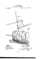
Be it known that I, CHARLES M. PEARRE, of the city and county of Galveston, and State of Texas, have invented a new and Improved Bale-Band Stretcher; and 1 do hereby declare that the following is a full, clear, and exact description of the same, reference being had to the accompanying drawing, forming part of this specification, in which- Figure l is a perspective view of the baleband stretcher in its open position. Fig. 2 is a perspective view of the same in its closed position. Fig. 3 is a view of the device applied to a cotton-bale in both its open and closed position.
The object of my invention is to provide a convenient and effective bale-band stretcher to be used in baling cotton, hay, 820., for the purpose of taking out the slack of the band that cannot be taken out by hand, while the bale is under the press; to which end my invention consists in a bar, carrying at its end a griping device for one end of the band, and a guide-socket, in combination with an elbow-lever, pivoted at its end to a slide-bar moving through said guide-socket, and carrying also a griping device for the other end of the band, which two griping devices are adapted to be brought together by bringing the handles of the elbow-lever and bar together, and tilting the elbow-lever upon its angle, at which point it is attached to the bar by a keeper, and slides over an inclined portion of the same upon rollers, as hereinafter more fully described.
In the drawing, A B represent the griping devices that hold the bent ends of the band, the first of which, A, is located upon the side of the end of bar C, while the second, B, is 10- caled upon the side of the lower end of slidebar X. These griping devices consist of four projecting plates or lugs, having three intervening slots, of which the two outside slots areintended to receive the bent ends of the band, while the central slot is made deeper than the rest, and is intended to accommodate the bale-tie, which is slipped into the same, so as to connect the two bent ends of the band when brought together. D is an elbow-lever, the outer arm of which is pivoted to the top of the slide-bar X, which latter passes through the guide-socket a, formed in the end of the bar 0 beside the griping device A, so that the two griping devices A and B are brought together in alignment. The said elbow-lever isprovided with a keeper or strap, 1), that embraces the bar 0, and carries upon opposite sides of said bar friction-rollers c g, which move upon a curved or inclined portioinf, of the bar 0.
In making use of the bale-band stretcher, as thus described, it is applied to the bale of cotton, as shown in Fig. 3, with the bar 0 at right angles to the side of the bale, and the handle of the elbow-lever I) nearly vertical, in which position the griping devices are farthest apart. The ends of the band are then passed through the outside slots of the griping devices, and after being bent around are turned inwardly next to the bale, and passed through the inside slots, so as to have the free ends of the band inside, and next to the bale. The handle or elbow-lever is then brought down to bar 0, bringing the griping devices together, and tightening the bale-band, while a tie, such as is shown in detail at G, is inserted in the deep central slot of the griping devices, and around the bent ends of the band, so as to securely hold the same after the stretcher is removed.
in bringing the handle of the elbow-lever down it will be seen that its outer arm rises with the slide-bars X, while its angle moves upon the rollers along the incline f of the bar 0 until the arm of the elbow-lever is parallel with the bar X, as shown in Fig. 2; and I am thus enabled to avail myself of the greatest advantages of leverage at the end of the movement, and at the time when it is most required, the incline eo-operating to give a greater throw to the bar X and griping device at the end of the movement, and an easier movement at the start.
In Fig. 3 four of the hands are shown with the slack all taken out, and the band secured by means of my improved stretcher, while the rest represent those in which the slack has been partially taken out by hand, and to which my stretcher is shown applied in both its open and closed position for completing the tightening and securing ot' the tie.
By means of my improved stretcher I am enabled to take from eight to fourteen inches of slack'out of a band more than can be done by hand, whereby the bale may he reduced in dimension, so as to occupy 211 much smaller space.
Having thus described'iny invention; what lclainrasnewisr r l. The gripers A and"B,-arrenged 'tzo he separated or brought together; and hau ing" projectinglngsor plates forming-e central "deep slot for the reception 0fthebale-tie,and
shallower slots for the band, substantially as" and for the purpose described.
2. The bar 0, carrying a griping' device at its end, and a guide, in combination with the slide-ber'X, having argriping device, and" moving insaid guide, and the elbow-lever D,
having one arm pivoted to the bar X; and moving at its angle upon har'O by means of rollers and keepers, substantially as described. 3. The bar 0, curved or inclined at f; and
carrying socket a, andn griping device, in'
combination with the bar X, carrying e griping device, and the 'elbow'le ver '1'), substan tially as and for the purpose described.
CHARLES M. 'PE ARRE; Witnesses:
'J. P. JOHNSON,
HENRY G. NoLn.
Publications (1)
| Publication Number | Publication Date |
|---|---|
| US185347A true US185347A (en) | 1876-12-12 |
Family
ID=2254753
Family Applications (1)
| Application Number | Title | Priority Date | Filing Date |
|---|---|---|---|
| US185347D Expired - Lifetime US185347A (en) | Improvement in bale-band stretchers |
Country Status (1)
| Country | Link |
|---|---|
| US (1) | US185347A (en) |
-
0
- US US185347D patent/US185347A/en not_active Expired - Lifetime
Similar Documents
| Publication | Publication Date | Title |
|---|---|---|
| US185347A (en) | Improvement in bale-band stretchers | |
| US136640A (en) | Improvement in devices for coupling cars | |
| US699322A (en) | Packaging sheet-metal sections. | |
| US54810A (en) | Improvement in machines for tightening and securing the hoops of compressed bales | |
| US223048A (en) | Improvement in canvas covers for barrels | |
| US1132131A (en) | Baling-press. | |
| US1379299A (en) | Bill-file | |
| US151483A (en) | Improvement in bale-ties | |
| US403530A (en) | Metallic strap for boxes | |
| US436706A (en) | Device for securing hose-bands | |
| US1151399A (en) | Wire-tightener. | |
| US220636A (en) | Improvement in bale-band benders | |
| US302243A (en) | Lemuel e | |
| US374372A (en) | Andeew j | |
| US112375A (en) | Improvement in bale-ties | |
| US326419A (en) | Wire-stretcher | |
| US1126325A (en) | Sole-press. | |
| US902864A (en) | Bale-tie. | |
| US59141A (en) | Improvement in cotton-bale ties | |
| US427190A (en) | Shock-compressor | |
| US363569A (en) | Implement for buckling bale-ties | |
| US291179A (en) | Press-platen | |
| US277432A (en) | Amos a | |
| US220770A (en) | Improvement in coin-holders | |
| US291560A (en) | Assionob op one-h |