US1853150A - Spring controlled roller for roller blinds - Google Patents
Spring controlled roller for roller blinds Download PDFInfo
- Publication number
- US1853150A US1853150A US418579A US41857930A US1853150A US 1853150 A US1853150 A US 1853150A US 418579 A US418579 A US 418579A US 41857930 A US41857930 A US 41857930A US 1853150 A US1853150 A US 1853150A
- Authority
- US
- United States
- Prior art keywords
- roller
- spring
- blind
- bearing
- spring controlled
- Prior art date
- Legal status (The legal status is an assumption and is not a legal conclusion. Google has not performed a legal analysis and makes no representation as to the accuracy of the status listed.)
- Expired - Lifetime
Links
- 230000008878 coupling Effects 0.000 description 1
- 238000010168 coupling process Methods 0.000 description 1
- 238000005859 coupling reaction Methods 0.000 description 1
- 238000000034 method Methods 0.000 description 1
- 238000003825 pressing Methods 0.000 description 1
- 238000004804 winding Methods 0.000 description 1
Images
Classifications
-
- E—FIXED CONSTRUCTIONS
- E06—DOORS, WINDOWS, SHUTTERS, OR ROLLER BLINDS IN GENERAL; LADDERS
- E06B—FIXED OR MOVABLE CLOSURES FOR OPENINGS IN BUILDINGS, VEHICLES, FENCES OR LIKE ENCLOSURES IN GENERAL, e.g. DOORS, WINDOWS, BLINDS, GATES
- E06B9/00—Screening or protective devices for wall or similar openings, with or without operating or securing mechanisms; Closures of similar construction
- E06B9/56—Operating, guiding or securing devices or arrangements for roll-type closures; Spring drums; Tape drums; Counterweighting arrangements therefor
- E06B9/60—Spring drums operated only by closure members
Definitions
- Thisinvention relates to aspring controlled the roller according to the invention in the roller for roller blinds, route indicators and dismounted condition with the clutch memthe like, in which the blind or the strip bearher in engagement.- ing the route indications is kept taut in any In the drawings a is the spring controlled particular position of the bottom bar of the roller, 4" the blind or the strip bearing the "blind by the stressing of the helical spring charactersmthe bottom blind rod and p and g which actuates the roller and by means prothe lateral bearings which are screwed inside vided on the said bottom bar and in which the the window frame and in which the roller a raising and lowering of the blind or strip is is journalled.
- the roller a consists of the M effected automatically through the stressing tubular shell part m, the enddisc o fixed rigof the roller spring through the said bottom idly to it and having the round journal 0 bar being pushed up and down by hand, the the end ring e also fixed rigidly to the shell blind or strip winding up on to the spring part m and the two bearing discs h and Z also roller. fixed to the shell part.:
- the spring con- The present invention relates to a spring trolled roller a is rotatable with its bearing controlled roller of the kind stated, which is discs h and Z andthe end ring 6 on the roller provided with an arrangement for enabling shaft d.
- the spring controlled roller which projects it and the bearing disc Z the helical spring 71 out of the latter, and the bearing belonging which actuates the roller is fixed in a known 3o toit are so constructed that the roller shaft manner at one end at s to the roller shaft (Z cannot be turned when the roller is in posiand at the other end to the bearing disc Z. tion.
- the free end of the roller is suitably n is the free end of the roller shaft cl which made square and the bearing belonging to it projects out of the roller a and is preferably rovided with a corresponding square hole. made square.
- the hole in the lateral bearing 5 The novel feature of the roller blind aois correspondingly square.
- the other latcording to the invention is that within the eralbearing g has a round hole for receiving spring controlled roller is a clutch arrangethe round journal 0. ment by which the spring actuating the roller For stressing the spring 6 before the roller is'held in its stressed state while the roller is is placed n Position, h T011611 a is rm- 40 being placed in position and removed, ly in one hand and the end journal at of the 3
- the roller a is pushed on the roller shaft 03 in the direction of the bearing 9 until the bearing q, releases the round journal 0 when the roller a can be withdrawn from the bearing p. This will cause the clutch f to engage automatically through the action of the spring 9 with the teeth 6 on the end ring 6, so that the spring is kept in its stressed condition.
- the roller blind according to the invention has this advantage over the known devices of this kind that the blind or the strip bearing the characters can occupy almost the entire width of the window frame and that, when letting up the blind or strip, there can be no check owing to the sudden engagement of the clutch member due to its centrifugal force.
- the spring a being fixed to the bearing disc Z it may be fixed to a carriage which is slidable in the tubular shell m, but secured from turning in the same.
- any other suitable coupling members may be used.
- a roller for shades including a hollow body part, a plurality of internal spaced bearing members therein, a single rotatable spindle passing through said bearings and rotatable and axially movable therein, spring means normally tending to turn said spindle.
- second spring means normally tending to displace the spindle axially, a clutch member carried by the body member, and a clutch member carried by the spindle, the second mentioned clutch member being under the influence of the second spring means, the second spring means being confined between the second clutch member and one of said bearings.
Landscapes
- Engineering & Computer Science (AREA)
- Structural Engineering (AREA)
- Architecture (AREA)
- Civil Engineering (AREA)
- Operating, Guiding And Securing Of Roll- Type Closing Members (AREA)
Description
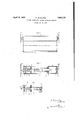
April 12, 1932. P.'SCHULTES SPRING CONTROLLED ROLLER FOR ROLLER BLTNDS Filed Jan, 4, 1930 NvE/xlTaZ Patented iApr. i 1932. i .1 v r 1 53 159 UNITErm STATES PATENT" OFFEQE PAUL SCHULTES, F LEIGHLINGEN, GERMANY SPRING CONTROLLED ROLLER FOR ROLLER BLINDS Application filed January 4, 1930, Serial No. 418,579, and inGermany July 4, 1929.
Thisinvention relates to aspring controlled the roller according to the invention in the roller for roller blinds, route indicators and dismounted condition with the clutch memthe like, in which the blind or the strip bearher in engagement.- ing the route indications is kept taut in any In the drawings a is the spring controlled particular position of the bottom bar of the roller, 4" the blind or the strip bearing the "blind by the stressing of the helical spring charactersmthe bottom blind rod and p and g which actuates the roller and by means prothe lateral bearings which are screwed inside vided on the said bottom bar and in which the the window frame and in which the roller a raising and lowering of the blind or strip is is journalled. The roller a consists of the M effected automatically through the stressing tubular shell part m, the enddisc o fixed rigof the roller spring through the said bottom idly to it and having the round journal 0 bar being pushed up and down by hand, the the end ring e also fixed rigidly to the shell blind or strip winding up on to the spring part m and the two bearing discs h and Z also roller. fixed to the shell part.: The spring con- The present invention relates to a spring trolled roller a is rotatable with its bearing controlled roller of the kind stated, which is discs h and Z andthe end ring 6 on the roller provided with an arrangement for enabling shaft d. Between the end ring 6 and the the spring which actuates the roller to be hearing disc hthere is fixed on the roller shaft stressed and unstressed so as to give the d by-means of the pin it a clutch member f spring the requisite tension before placing provided withratchet-teeth f Between the 50 Fig. 3 is a longltudinal section of part of far to disengage the clutch f; By this means the roller in its bearings and to keep the clutch member f and the bearing disc h and spring sotensioned while the roller in being wound round the roller shaft (Z there is a placed in the bearings and removed therehelical'springg by which the roller shaft (Z from, that is to prevent the spring running with the clutch member f is forced inthe di- F d rection of the end ring 6. The end ring e For this purpose according to the invenhas ratchet teeth 6 on the side facing the tion the end of the roller shaft supporting clutchmember 7. Between the bearing disc the spring controlled roller, which projects it and the bearing disc Z the helical spring 71 out of the latter, and the bearing belonging which actuates the roller is fixed in a known 3o toit are so constructed that the roller shaft manner at one end at s to the roller shaft (Z cannot be turned when the roller is in posiand at the other end to the bearing disc Z. tion. The free end of the roller is suitably n is the free end of the roller shaft cl which made square and the bearing belonging to it projects out of the roller a and is preferably rovided with a corresponding square hole. made square. The hole in the lateral bearing 5 The novel feature of the roller blind aois correspondingly square. The other latcording to the invention is that within the eralbearing g has a round hole for receiving spring controlled roller is a clutch arrangethe round journal 0. ment by which the spring actuating the roller For stressing the spring 6 before the roller is'held in its stressed state while the roller is is placed n Position, h T011611 a is rm- 40 being placed in position and removed, ly in one hand and the end journal at of the 3 The invention is illustrated by way of exroller shaft'cl turned by means of a key placed ample in the accompanying drawings, in on the square end until the spring i is suffi which ciently stressed. On=the key being removed Fig. 1 shows in elevation a roller blind with he cl tch f will engage automatically and the a spring controlled roller according to th springz'be held in its stressed condition. The inventionwhen in position, bearings 79 and 9 must be screwed to their Fig; 2 the spring controlled roller accord- HPP I'tS in Such a m nner that when placing to the invention .in longitudinal section ing the roller in position the shaft (Z with the when in position and end journal at can be pushed back sufficiently the spring is released for operating the blind. On the blind being drawn down, the spring z'is additionally stressed and on the blind being released, it will freely fly up automatically. For holding the blind at any desired intermediate height any of the ordinary commercially obtainable means may be used at the bottom end of the blind.
en removing the roller blind, the roller a is pushed on the roller shaft 03 in the direction of the bearing 9 until the bearing q, releases the round journal 0 when the roller a can be withdrawn from the bearing p. This will cause the clutch f to engage automatically through the action of the spring 9 with the teeth 6 on the end ring 6, so that the spring is kept in its stressed condition.
If the spring 71 is to be further stressed or unstressed, the procedure is thesame as that described above for stressing the spring, only that, when unstressing the spring 11 the roller shaft 03 is turned in the opposite direction, the clutch member 7 being disengaged by applying pressure towards the end journal 02.
The roller blind according to the invention has this advantage over the known devices of this kind that the blind or the strip bearing the characters can occupy almost the entire width of the window frame and that, when letting up the blind or strip, there can be no check owing to the sudden engagement of the clutch member due to its centrifugal force.
Instead of the spring a being fixed to the bearing disc Z it may be fixed to a carriage which is slidable in the tubular shell m, but secured from turning in the same.
In place of the ratchet teeth f and 6 any other suitable coupling members may be used.
Having now particularly described and ascertained the nature of my said invention and in what manner the same is to be per formed. I declare that what I claim is:
A roller for shades including a hollow body part, a plurality of internal spaced bearing members therein, a single rotatable spindle passing through said bearings and rotatable and axially movable therein, spring means normally tending to turn said spindle. second spring means normally tending to displace the spindle axially, a clutch member carried by the body member, and a clutch member carried by the spindle, the second mentioned clutch member being under the influence of the second spring means, the second spring means being confined between the second clutch member and one of said bearings.
In testimony whereof I aflix my signature.
PAUL SCHULTES.
Applications Claiming Priority (1)
| Application Number | Priority Date | Filing Date | Title |
|---|---|---|---|
| DE1853150X | 1929-07-04 |
Publications (1)
| Publication Number | Publication Date |
|---|---|
| US1853150A true US1853150A (en) | 1932-04-12 |
Family
ID=7746098
Family Applications (1)
| Application Number | Title | Priority Date | Filing Date |
|---|---|---|---|
| US418579A Expired - Lifetime US1853150A (en) | 1929-07-04 | 1930-01-04 | Spring controlled roller for roller blinds |
Country Status (1)
| Country | Link |
|---|---|
| US (1) | US1853150A (en) |
Cited By (11)
| Publication number | Priority date | Publication date | Assignee | Title |
|---|---|---|---|---|
| US5036898A (en) * | 1990-01-02 | 1991-08-06 | Chen Wen H | Continuously unfurlable car window shade |
| US20050087642A1 (en) * | 2002-02-19 | 2005-04-28 | Dalex S.R.L. | Operation group for automatically winding up curtains |
| US20050205224A1 (en) * | 2002-02-19 | 2005-09-22 | Dalex S.R.L. | Operation group for curtains with winding up roll |
| US20070074829A1 (en) * | 2005-10-03 | 2007-04-05 | Wieczorek Joseph P | Window shade |
| WO2007128288A1 (en) * | 2006-05-09 | 2007-11-15 | Webasto Ag | Roller blind arrangement |
| EP1970236A1 (en) * | 2007-03-15 | 2008-09-17 | Centre d'Etude et de Recherche pour l'Automobile (CERA) | Winding system for a blind for a vehicle component with a roller blind, comprising a locking device that can be deactivated during its assembly |
| GB2481448A (en) * | 2010-06-25 | 2011-12-28 | Levolux At Ltd | Roller blind compensator apparatus |
| CN102712239A (en) * | 2010-01-20 | 2012-10-03 | 芦森工业株式会社 | Sunshade device |
| WO2021174285A1 (en) * | 2020-03-02 | 2021-09-10 | ScreenAway Holdings Limited | Spring assist system |
| US12252932B2 (en) | 2021-09-01 | 2025-03-18 | Ublockout Technologies Pty Ltd | Lockable corner bracket |
| US12331590B1 (en) * | 2024-07-19 | 2025-06-17 | Jiani Zhong | Curtain roller |
-
1930
- 1930-01-04 US US418579A patent/US1853150A/en not_active Expired - Lifetime
Cited By (21)
| Publication number | Priority date | Publication date | Assignee | Title |
|---|---|---|---|---|
| US5036898A (en) * | 1990-01-02 | 1991-08-06 | Chen Wen H | Continuously unfurlable car window shade |
| US20050087642A1 (en) * | 2002-02-19 | 2005-04-28 | Dalex S.R.L. | Operation group for automatically winding up curtains |
| US20050205224A1 (en) * | 2002-02-19 | 2005-09-22 | Dalex S.R.L. | Operation group for curtains with winding up roll |
| US7147030B2 (en) * | 2002-02-19 | 2006-12-12 | Dalex S.R.L. | Operation group for curtains with winding up roll |
| US20070074829A1 (en) * | 2005-10-03 | 2007-04-05 | Wieczorek Joseph P | Window shade |
| US7597132B2 (en) * | 2005-10-03 | 2009-10-06 | Irvin Automotive Products, Inc. | Window shade |
| WO2007128288A1 (en) * | 2006-05-09 | 2007-11-15 | Webasto Ag | Roller blind arrangement |
| EP1970236A1 (en) * | 2007-03-15 | 2008-09-17 | Centre d'Etude et de Recherche pour l'Automobile (CERA) | Winding system for a blind for a vehicle component with a roller blind, comprising a locking device that can be deactivated during its assembly |
| FR2913715A1 (en) * | 2007-03-15 | 2008-09-19 | Cera | SYSTEM FOR WINDING A CURTAIN COMPONENT WITH A ROLL-UP CURTAIN OF A MOTOR VEHICLE, COMPRISING A LOCKING DEVICE THAT IS DISABLED DURING THE ASSEMBLY |
| CN102712239A (en) * | 2010-01-20 | 2012-10-03 | 芦森工业株式会社 | Sunshade device |
| US20120305204A1 (en) * | 2010-01-20 | 2012-12-06 | Ashimori Industry Co., Ltd | Sunshade device |
| US8607843B2 (en) * | 2010-01-20 | 2013-12-17 | Ashimori Industry Co., Ltd. | Sunshade device |
| CN102712239B (en) * | 2010-01-20 | 2015-03-25 | 芦森工业株式会社 | Sunshade device |
| GB2481448A (en) * | 2010-06-25 | 2011-12-28 | Levolux At Ltd | Roller blind compensator apparatus |
| WO2021174285A1 (en) * | 2020-03-02 | 2021-09-10 | ScreenAway Holdings Limited | Spring assist system |
| US20230340834A1 (en) * | 2020-03-02 | 2023-10-26 | Screenaway Usa Pty Ltd | Spring assist system |
| US12378817B2 (en) * | 2020-03-02 | 2025-08-05 | Ublockout Technologies Pty Ltd | Spring assist system |
| AU2021229903B2 (en) * | 2020-03-02 | 2026-01-22 | Ublockout Technologies Pty Ltd | Spring assist system |
| US12252932B2 (en) | 2021-09-01 | 2025-03-18 | Ublockout Technologies Pty Ltd | Lockable corner bracket |
| US12435563B2 (en) | 2021-09-01 | 2025-10-07 | Ublockout Technologies Pty Ltd | Lockable corner bracket |
| US12331590B1 (en) * | 2024-07-19 | 2025-06-17 | Jiani Zhong | Curtain roller |
Similar Documents
| Publication | Publication Date | Title |
|---|---|---|
| US1853150A (en) | Spring controlled roller for roller blinds | |
| US2520629A (en) | Automatically operated venetian blind | |
| US1779349A (en) | Mechanical toy | |
| US1941880A (en) | Reel | |
| US873438A (en) | Spring shade-roller. | |
| US1999457A (en) | Winding key | |
| US755675A (en) | Curtain-fixture. | |
| US1371149A (en) | Flexible-wall construction | |
| US1535502A (en) | Mechanical spinning top | |
| US1570607A (en) | Pulling device | |
| US1568203A (en) | Shade-roller-operating mechanism | |
| US1746936A (en) | Roller blind and fitting therefor | |
| GB339506A (en) | ||
| US1053658A (en) | Shade-roll-operating device. | |
| US772408A (en) | Cane. | |
| US1019653A (en) | Window-shade roller. | |
| US33708A (en) | Improved curtain-fixture | |
| US2025656A (en) | Shade roller | |
| US2094178A (en) | Window shade | |
| US94866A (en) | Improved window-shade fixture | |
| US78361A (en) | Robert j | |
| US31643A (en) | Bons l | |
| US1898680A (en) | Top-spinning device | |
| US36395A (en) | Improvement in stereoscopes | |
| US1818509A (en) | Changeable sign |