US185309A - Improvement in attaching hubs to axles - Google Patents
Improvement in attaching hubs to axles Download PDFInfo
- Publication number
- US185309A US185309A US185309DA US185309A US 185309 A US185309 A US 185309A US 185309D A US185309D A US 185309DA US 185309 A US185309 A US 185309A
- Authority
- US
- United States
- Prior art keywords
- disk
- hub
- improvement
- axles
- screw
- Prior art date
- Legal status (The legal status is an assumption and is not a legal conclusion. Google has not performed a legal analysis and makes no representation as to the accuracy of the status listed.)
- Expired - Lifetime
Links
- 210000003739 neck Anatomy 0.000 description 4
- 238000010276 construction Methods 0.000 description 2
- 230000000284 resting effect Effects 0.000 description 2
- 230000027455 binding Effects 0.000 description 1
- 239000010985 leather Substances 0.000 description 1
- 239000002184 metal Substances 0.000 description 1
Images
Classifications
-
- B—PERFORMING OPERATIONS; TRANSPORTING
- B60—VEHICLES IN GENERAL
- B60B—VEHICLE WHEELS; CASTORS; AXLES FOR WHEELS OR CASTORS; INCREASING WHEEL ADHESION
- B60B37/00—Wheel-axle combinations, e.g. wheel sets
- B60B37/10—Wheel-axle combinations, e.g. wheel sets the wheels being individually rotatable around the axles
Definitions
- My improvement relates to means for securing the hub to the axle at the inner end of' the hub, thereby leaving the outer end of the hub closed.
- Devices for this purpose are already known 5 hence I do not claim such, broadly.
- My invention consists of a locking-disk at the inner end of the hub, provided with slots having enlarged sockets at their ends, in combination with T-headed studs and a conical clamping-screw, as and for the purposes hereinafter more fully described.
- A is the hub, the outer end of which is closed.
- B is the axle.
- B is its journal, and B the collar.
- 0 is the box in which thejournal rests, being closed at its outer end.
- a a are leather or other packing-rings, resting on opposite sides of the collar B
- D is the lockingdisk. It is a thin plate of metal, which rests closely around the axle, against the collar, and abuts against the inner end of It has a central offset, 1), which incloses the packing-ring a.
- In the body of the disk are three or more concentric slots, E E E.
- Each of these slots has an enlarged opening, 0, at one end, a smaller opening, 0 at the other end, and a narrow neck, connecting the two openings. This is clearly shown in Figs. 2 and 4.
- the smaller opening 0 is of somewhat larger diameter than the neck, and its edges are beveled outward to receive the conical tightening-screw, as shown at j, Figs. 1 and 4.
- G G are T-heads, permanently attached to the inner end of the hub, and standin g outward therefrom.
- H is a screw, which passes through the'third slot of the locking-disk, and enters the end of the hub. It consists of a threaded end, f, which holds in the hub a conical body, j', which rests in the beveled smaller opening c of the disk, and a square head, f by which the screw is turned.
- the large openings 0 c are placed over the T- headed studs Gr G, and the disk is then turned, bringing the necks c c beneath the said T-heads, which holds the hub fast to the disk.
- the screw His then turned down in the small opening 0 so that the cone f fits closely in the beveled surface .the hub.
- the disk being close-fitting under the T- heads, this binding action of the screw makes a close fit of the whole disk to the hub, so that no loose action or rattling can occur, which is a matter of much importance.
- the two parts are joined together as one fixture.
- the screw is simply turned back one or two turns, which releases the disk. The latter can then be turned so as to remove it from the T- heads, which frees the hub from the axle.
- g g are holes near the edge of the disk, in which to insert the point or pin of a wrench
Landscapes
- Engineering & Computer Science (AREA)
- Mechanical Engineering (AREA)
- Connection Of Plates (AREA)
Description
C.FLESCH- ms T0 AXLES.
Patent mmcmm Dec. 1 1
the hub.
CHARLES FLESG H, OF ROCHESTER, NEWYORK, ASSIGNOR ONE-HALF OF HIS RIGHT TO JOSEPH RIPPIN, OF SAME PLACE.
IMPROVEMENT lN ATTACHiNG HUBS TOAXLES:
Specification forming part of Letters Patent No. 185.309, dated December 12, 1876; application filed October 7, 1876. v
To all whom it may concern:
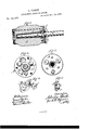
Be it known that I, CHARLES FLEsoH, of the city of Rochester, in the county of Monroe and State of New York, have invented a certain new and useful Improvement in Carriage-W'heels; and I do hereby declare that the following is a full, clear, and exact descriptionof the construction and operation of the same, reference being had to the accompanying drawings, in which- Figure lis a section of a carriage-hub, showing my improvement. Fig. 2 is an end view of the same. Fig. 3 is a similar view with the locking-disk removed'from place. Figs. 4 and 5 are detail views, showing the means for securing the locking-disk.
My improvement relates to means for securing the hub to the axle at the inner end of' the hub, thereby leaving the outer end of the hub closed. Devices for this purpose are already known 5 hence I do not claim such, broadly.
My invention consists of a locking-disk at the inner end of the hub, provided with slots having enlarged sockets at their ends, in combination with T-headed studs and a conical clamping-screw, as and for the purposes hereinafter more fully described.
A is the hub, the outer end of which is closed. B is the axle. B is its journal, and B the collar. 0 is the box in which thejournal rests, being closed at its outer end. a a are leather or other packing-rings, resting on opposite sides of the collar B Thus far the wheel is of ordinary construction. D is the lockingdisk. It is a thin plate of metal, which rests closely around the axle, against the collar, and abuts against the inner end of It has a central offset, 1), which incloses the packing-ring a. In the body of the disk are three or more concentric slots, E E E. Each of these slots has an enlarged opening, 0, at one end, a smaller opening, 0 at the other end, and a narrow neck, connecting the two openings. This is clearly shown in Figs. 2 and 4. The smaller opening 0 is of somewhat larger diameter than the neck, and its edges are beveled outward to receive the conical tightening-screw, as shown at j, Figs. 1 and 4. G G are T-heads, permanently attached to the inner end of the hub, and standin g outward therefrom. They are of a diameter smaller than the large openings 0 c of the lockingdisk, but larger than the small openings c c or the necks 0 so that when the locking-disk is inserted over thestuds and turned around, said locking-disk will be held by the Theads, as shown in Fig. 5. H is a screw, which passes through the'third slot of the locking-disk, and enters the end of the hub. It consists of a threaded end, f, which holds in the hub a conical body, j', which rests in the beveled smaller opening c of the disk, and a square head, f by which the screw is turned. The large openings 0 c are placed over the T- headed studs Gr G, and the disk is then turned, bringing the necks c c beneath the said T-heads, which holds the hub fast to the disk. The screw His then turned down in the small opening 0 so that the cone f fits closely in the beveled surface .the hub. The disk being close-fitting under the T- heads, this binding action of the screw makes a close fit of the whole disk to the hub, so that no loose action or rattling can occur, which is a matter of much importance. The two parts are joined together as one fixture.
Much difficulty has heretofore been-eXpe-I rienced in so securing the parts as to prevent looseness and rattling, as very great strain comes at this point. The single conical screw, fitting in its corresponding beveled seat, in connection with the T- heads, obviates all difficulty of the kind.
To remove the wheel from the axle, the screw is simply turned back one or two turns, which releases the disk. The latter can then be turned so as to remove it from the T- heads, which frees the hub from the axle.
g g are holes near the edge of the disk, in which to insert the point or pin of a wrench,
to turn the disk if it should stick.
7 Having thus describedmy invention, I do said screw resting in a beveled seatof the not claim, broadly, a slotted collar held by smallersocket, as and forthe purpose specified. screws but In witness whereof I have hereunto signed What I claim as new islily name in the presence of two subscribing In a carriage-wheel, the locking-disk D, prowitnesses. vided with slots E E E, having the enlarged sockets c at one end, and the slnaller sockets CHARLES FLESOH c at the other, in combination with fixed T- Witnesses headed studs G G, fitting in two of the slots, R. F. OSGOOD,
and the conical screw H, fitting in the third, EDWIN SCOTT.
Publications (1)
| Publication Number | Publication Date |
|---|---|
| US185309A true US185309A (en) | 1876-12-12 |
Family
ID=2254714
Family Applications (1)
| Application Number | Title | Priority Date | Filing Date |
|---|---|---|---|
| US185309D Expired - Lifetime US185309A (en) | Improvement in attaching hubs to axles |
Country Status (1)
| Country | Link |
|---|---|
| US (1) | US185309A (en) |
Cited By (1)
| Publication number | Priority date | Publication date | Assignee | Title |
|---|---|---|---|---|
| US20090080546A1 (en) * | 2005-03-30 | 2009-03-26 | Matsushita Electric Industrial Co., Ltd. | Limitation feedback method for multiantenna system, channel parameter generating method, and wireless receiver |
-
0
- US US185309D patent/US185309A/en not_active Expired - Lifetime
Cited By (1)
| Publication number | Priority date | Publication date | Assignee | Title |
|---|---|---|---|---|
| US20090080546A1 (en) * | 2005-03-30 | 2009-03-26 | Matsushita Electric Industrial Co., Ltd. | Limitation feedback method for multiantenna system, channel parameter generating method, and wireless receiver |
Similar Documents
| Publication | Publication Date | Title |
|---|---|---|
| US185309A (en) | Improvement in attaching hubs to axles | |
| US222556A (en) | whitman | |
| US430687A (en) | eeinhold | |
| US214623A (en) | Improvement in brake-shoes | |
| US608855A (en) | Advertising device | |
| US1011982A (en) | Brake-shoe. | |
| US720984A (en) | Tackle-block. | |
| US491937A (en) | Wheel-hub | |
| US221701A (en) | Improvement in hub-attaching devices | |
| US425252A (en) | Sand-band | |
| US1134136A (en) | Trolley-head. | |
| US1170668A (en) | Demountable wheel. | |
| US439670A (en) | Car-wheel | |
| US353052A (en) | Chaeles albeet coopee | |
| US659857A (en) | Caster. | |
| US241816A (en) | Matthias miller | |
| US1046231A (en) | Disk-mounting. | |
| US656607A (en) | Car-axle-box lid. | |
| US463272A (en) | Hub and axle | |
| US222683A (en) | Improvement in vehicle-wheel hubs | |
| US1015248A (en) | Neck-yoke center. | |
| US421341A (en) | William ii | |
| USD32545S (en) | Design for a draft-plate for cars | |
| US164005A (en) | Improvement in paper boxes | |
| US441916A (en) | Singletree |