US1853033A - Permanent hair waver - Google Patents
Permanent hair waver Download PDFInfo
- Publication number
- US1853033A US1853033A US488380A US48838030A US1853033A US 1853033 A US1853033 A US 1853033A US 488380 A US488380 A US 488380A US 48838030 A US48838030 A US 48838030A US 1853033 A US1853033 A US 1853033A
- Authority
- US
- United States
- Prior art keywords
- hair
- clamp
- sleeve
- members
- rods
- Prior art date
- Legal status (The legal status is an assumption and is not a legal conclusion. Google has not performed a legal analysis and makes no representation as to the accuracy of the status listed.)
- Expired - Lifetime
Links
- 210000004761 scalp Anatomy 0.000 description 10
- XLYOFNOQVPJJNP-UHFFFAOYSA-N water Substances O XLYOFNOQVPJJNP-UHFFFAOYSA-N 0.000 description 6
- 230000005494 condensation Effects 0.000 description 5
- 238000009833 condensation Methods 0.000 description 5
- 230000000295 complement effect Effects 0.000 description 4
- 208000027418 Wounds and injury Diseases 0.000 description 3
- 230000001012 protector Effects 0.000 description 3
- ISWSIDIOOBJBQZ-UHFFFAOYSA-N Phenol Chemical compound OC1=CC=CC=C1 ISWSIDIOOBJBQZ-UHFFFAOYSA-N 0.000 description 2
- 239000007859 condensation product Substances 0.000 description 2
- 239000004020 conductor Substances 0.000 description 2
- 230000002939 deleterious effect Effects 0.000 description 2
- 229920001342 Bakelite® Polymers 0.000 description 1
- 238000004873 anchoring Methods 0.000 description 1
- 239000004637 bakelite Substances 0.000 description 1
- 238000010276 construction Methods 0.000 description 1
- 230000006378 damage Effects 0.000 description 1
- 230000000994 depressogenic effect Effects 0.000 description 1
- 208000014674 injury Diseases 0.000 description 1
- 239000000463 material Substances 0.000 description 1
- 238000000034 method Methods 0.000 description 1
- 230000002093 peripheral effect Effects 0.000 description 1
- 230000001681 protective effect Effects 0.000 description 1
Images
Classifications
-
- A—HUMAN NECESSITIES
- A45—HAND OR TRAVELLING ARTICLES
- A45D—HAIRDRESSING OR SHAVING EQUIPMENT; EQUIPMENT FOR COSMETICS OR COSMETIC TREATMENTS, e.g. FOR MANICURING OR PEDICURING
- A45D2/00—Hair-curling or hair-waving appliances ; Appliances for hair dressing treatment not otherwise provided for
- A45D2/02—Hair winders or hair curlers for use substantially perpendicular to the scalp, i.e. steep-curlers
- A45D2/06—Hair winders or hair curlers for use substantially perpendicular to the scalp, i.e. steep-curlers in the form of rods with base plate or base clamp
Definitions
- a further object of our invention is to pro# vide a novel form or hair clamp in which a V bodyis provided with a vcavity or depression for receiving the hair, which body has prefer-v ably pivotally associated therewith a clamp#A ing device or j aw of desired form,which devicel is adapted to force the hair into said cavity or depression and hold same securely therein.
- Y v y Y Itis also within the province of our inventionto provide a novel means foi-preventladapted to be associated withour apparatus,
- said means yprefer'ablyY taking theform of apairo flanged complementary members, pivoted together at able'clasp for'holding said members together, said members being preferably of water im,- pervious .and non-heat conducting material, such, for example, as the phenol condensation product, known to the trade as balrelite
- at leastfone of thehair waving and curling members may be provided with Vameans for forming' awave or curloffdierent size, said means, ifdesired, taking the formofa sleeve, and provided ing ythe4 condensation Adrip of the heater,v
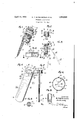
- Fig. 1 is a perspectivev view ofour invention applied to a lock or strand 4ot' hair, but with the'scalpprotector omitted
- F ig. ⁇ 2 is a cross-sectional view of our novel form of clamp,taken onthe line 2 2, Fig..1, ⁇ y y ,A
- Fig. 3 is a similar view, taken on the line 3 3, Fig. 2,
- Fig. 4 is aview similar vto Fig. 1with Vheater and scalpprotector in position,
- Fig. 5 is a somewhat enlarged cross-sectional View, takenonthe line 5 5, Fig. 4,
- Fig. 7 is a cross-sectional viewof the permanent hair waver, illustrating also they f means by which waves orfcurls may. be made f of .different sizes,
- FIG. 8 isan'enlarged sectional detail view of Fig..7, ⁇ andm Jfragmentary crossythe loweroend .of
- Fig..9' is ari/enlarged,cross-sectional views f' inv which a lock or strand of hair is anchored l by a suitabley anchoringmeans, such as a novel form ofhair clamping means, with f which is associated a means, ⁇ such as a pair. of members or rods, which maybe in par- -allelrelatiom and aboutwhichgthe hair is wound over and under to provide a succession of ydoubleloops, oney of said members or, rods, 'ifv desired, being yof greater length A than the other so the end of said hair ymay. be woundspirally thereaboutftoiorm a o curl, meansbeing also associated ywith the apparatus, and preferably with one of said members whereby the looped and curled hair may be held under tension.
- Another important feature of our invention resides in the means for preventingthe condensation drip of the heater from reach ⁇ n ing the scalp, which may be associated with said heater in such a way that such a deleterious result will be effectively prevented.
- our invention comprises a permanent hair waving apparatus having on one end a hair anchoring means or clamp 2, which may be of conventional form or that presently to be described, said clamp having associated therewith, in any manner in practice preferred, suitable members or rods 4 and 6, the rod 4 being rigidly secured to the clamp 2, while the rod or member 6 may take the form of a sleeve 8, crimped or otherwise associated with a rod 10 rigidly secured to the clamp 2, so that the sleeve 8 may be rotated about the rod 10 to place the required tension upon the hair as presently to be described.
- the lower end of the sleeve 8v is provided with a kerf 12, adapted to beengagedby a suitable tool whereby said sleeve 8 may be rotated upon the rigid rod or member10 ⁇ so that a variable tension may be placed upon the treated hair.
- the clamp 2 comprises a body 14 of any desired configuration and constructed of suitable material, and which body has on one side a plane face or surface 16, and on theother a cut-out portion or depression 18 in which the hair 20 is adapted tobe anchored.
- a bifurcation 22 adapted to receive a pintle 24, to which is hinged a preferably flexible member 26, and of such flexibility that the hair 20 will be effectively depressed and securely held within thecavity or depression 18 so it may be anchored therein, the other end of said flexible member having a loop 28 (Figs. 1 and 3) to engage on a projection 30 on the body 2, one end of said'v loop being hinged to the flexible member, while the other is hinged to the cam portion 32 ofl an operating lever 34.
- said cam portion engaging said body to apply an effective pressure upon said flexible member to force the hair 20 within the cavity or depression 18, the dotted lines in Fig. 3 showing the various positions of the parts of the clamp as the strand or lock of hair is being clamped in place.
- the hair 20 having been clamped-or anchored as seen in Fig. 1, the loose strand is passed over and under the members 6 and 4, successively, to form a succession of double loops 36, which take the form of a figure 8, and, if desired, the lower end of the looped hair may be wound upon the member 6 s irally to form the curl 38.
- a suitable tension is then placed upon the looped and curled hair by means of a suitable tool engaging the kerf 12, by which the sleeve 8 may be rotated.
- the treated hair is then ready for treatment by placing same in any conventional or other form ofheater 40 (Fig. 4).
- a protector 42 preferably constructed'of a water impervious and non-heat conducting material, such as the phenol condensation product, known to the trade as bakelite.7
- the protector 42 preferably consists of a pair of complementary members 44, of suitable shape and dimensions, and having cutout or cut-away portions 46 of such size as to engage the hair 20 above the clamp 2 so the water of condensation will effectively be prevented from reaching the scalp.
- the complementary members 44 are provided with depending flanges, which flanges are adapted to receive snugly the end of the casing. of the heater 40 (Fig. 4,) and are suitably hinged together as indicated by the reference numeral 50, while at the other end said members are provided with a suitable clasp orlocking means 52 of conventional or other form, overlapping members 3, with curved cam edges ⁇ 5 being provided to force the hair 20 between the cut-away portions 46, so as to fit snugly therein.
- themember 6 may be equipped with a detachable sleeve 54 (Figs. 7-9) the lower end of which has a cross pin 56 for engaging the kerf 12, so said sleeve may be rotated simultaneously with the sleeve 8 as hereinbefore described.
- a hair kwaving apparatus a positive hair clamp, a pair of hair wavingmembers associated with said clamp, said members be# ing adapted to have the hair looped over and under thereon to form a succession of double loops in compact juxtaposition, a heater adapted to be positioned over said members and said hair, and means associated with saidL clamp for preventing lany steamor hot water from reaching the scalp.
- a hair waving apparatus a hair clamp, a pair of parallel rods' extending from said clamp, saidrods being of unequal length, whereby both a wave and a curl may be given to said hair, a sleeve associated with at least one of said rods, and means associated with said sleeve and its rod whereby Vsaid sleeve may be locked to said rod.
- a scalp protective device V adapted for use in connection with a hair waving and curling apparatus,the combination of ⁇ a pair of peripherally flanged complementary members, peripheral pivot means for pivoting said ⁇ ing a pair of rods ofunequal length extending therefrom, said rods being adapted to have a lock of hair looped thereabout and wound into a spiral to provide a wave to said hair and a curl, means for preventing water of condensation from reaching the scalp, and
- a hair clamp comprising a body, a flexiblek member pivoted to said body,'a loop pivoted to said member, and anoperating lever pivoted to said loop, said lock of hair being ⁇ adapted'to be positioned between said flexible member and said body, on one side thereof, and said lever swung to the other side of said body, said loop straddling one end of said Y body, whereby said lock of hair will "be clamped between'said flexiblel member and body.
- said clamp comprising a body' provided with Va hair receiving depressiononA one side thereof, and hair clamping means, pivotally connected at one end of said body, said means being adapted to be swung about the other end of saidr body and positioned upon both sides thereof, whereby said hair will be clamped within said depression.
- clamp for clamping a lockV of hair, a pair of rods of unequaly length secured to said clamp and extending therefrom, and a sleeve assoprovided with means wherebysaid sleeve may be rotated on said rod;
- a hair clamp for clamping a lock of hair and means extending from said clamp whereby a Iwave may be given said lock of hair
- said clamp comprising a body, and plural means, pivoted toyone end of said "body, whereby said plural means maybe swung about said body and said lock of hair clamped between a part of said lplural means and said c cluding hair ywaving means, the combination 11ok f
Landscapes
- Hair Curling (AREA)
- Cosmetics (AREA)
Description
April 12, 1932 G. F. BoTscHr-:IDER ETAL 1,853,033
PERMANENT HAR wAvER Filed Oct. 13, 1930 Patented Apr., 12,1932.
UNITED; STATES PATE-Nr rec PERMANENT HAIR WAvER i Application-filed October 13,1930.' Serial No. 488,380.
'Our inventionrelates to permanent hair waving and hair curlingapparatus, in which hair may not only be quickly and eXpeditiousu ly given a permanent wave', and, if desired, lthe end portion thereof formed into a curl,
but will eectively prevent any condensation` drip yformed the heater from reaching the scalp. Y A' 'f n 'N v It accordinglyis anobj ect of our invention to provide `a novel form of permanent hair waving apparatusin which a khair holding member, such as a novel or conventional form of clamp has associated therewith, a'means l such as a set of preferably parallel members, -or ro`ds,and which may be both detachably and adjustably connectedfwith said clamp, whereby a strandy or lock' of hair may be held or clamped, looped over and under said membersor rods tol form a successionjof '20 double loops, means being 1 also provided whereby the looped hair maybe held under tension. f y
Y A further object of our invention is to pro# vide a novel form or hair clamp in which a V bodyis provided with a vcavity or depression for receiving the hair, which body has prefer-v ably pivotally associated therewith a clamp#A ing device or j aw of desired form,which devicel is adapted to force the hair into said cavity or depression and hold same securely therein. Y v y Y Itis also within the province of our inventionto provide a novel means foi-preventladapted to be associated withour apparatus,
from yreaching the. scalp, said means, yprefer'ablyY taking theform of apairo flanged complementary members, pivoted together at able'clasp for'holding said members together, said members being preferably of water im,- pervious .and non-heat conducting material, such, for example, as the phenol condensation product, known to the trade as balrelite It desired, falso, at leastfone of thehair waving and curling members may be provided with Vameans for forming' awave or curloffdierent size, said means, ifdesired, taking the formofa sleeve, and provided ing ythe4 condensation Adrip of the heater,v
one end,and providedat the other with a suitv with'a suitable lock for locking said sleeve to saidmembers.V y f TheV above, Vand further objects and kad,-k va'ntagesof our invention, as will herein-y aftermore fully' appear, vwe attainfby the` construction describedy inl thespecication and illustrated in the preferred form on the plrawings, forming a part of' our applicaion. f
Reference is hadto the accompanyingy drawings, in which similar reference characters denote similar parts. In the drawings,
Fig. 1 is a perspectivev view ofour invention applied to a lock or strand 4ot' hair, but with the'scalpprotector omitted, F ig.` 2 is a cross-sectional view of our novel form of clamp,taken onthe line 2 2, Fig..1,` y y ,A
Fig. 3 is a similar view, taken on the line 3 3, Fig. 2,
Fig. 4 is aview similar vto Fig. 1with Vheater and scalpprotector in position,
Fig. 5 is a somewhat enlarged cross-sectional View, takenonthe line 5 5, Fig. 4,
' Fig. Gleis an enlarged top plan view of the scalp protector,
Fig. 7 'is a cross-sectional viewof the permanent hair waver, illustrating also they f means by which waves orfcurls may. be made f of .different sizes,
f Fig. 8 isan'enlarged sectional detail view of Fig..7,`andm Jfragmentary crossythe loweroend .of
Fig..9'is ari/enlarged,cross-sectional views f' inv which a lock or strand of hair is anchored l by a suitabley anchoringmeans, such as a novel form ofhair clamping means, with f which is associated a means,`such as a pair. of members or rods, which maybe in par- -allelrelatiom and aboutwhichgthe hair is wound over and under to provide a succession of ydoubleloops, oney of said members or, rods, 'ifv desired, being yof greater length A than the other so the end of said hair ymay. be woundspirally thereaboutftoiorm a o curl, meansbeing also associated ywith the apparatus, and preferably with one of said members whereby the looped and curled hair may be held under tension. l
It is also within the province of our 1nvention to provide a means, such as at least one sleeve, adapted to be associated with one or both of said rods or members, wher'eby a Wave or a curl of different size may be made, means being also provided, if desired, for locking said sleeve to said rod or member.
Another important feature of our invention resides in the means for preventingthe condensation drip of the heater from reach`n ing the scalp, which may be associated with said heater in such a way that such a deleterious result will be effectively prevented.
More specifically our invention comprises a permanent hair waving apparatus having on one end a hair anchoring means or clamp 2, which may be of conventional form or that presently to be described, said clamp having associated therewith, in any manner in practice preferred, suitable members or rods 4 and 6, the rod 4 being rigidly secured to the clamp 2, while the rod or member 6 may take the form of a sleeve 8, crimped or otherwise associated with a rod 10 rigidly secured to the clamp 2, so that the sleeve 8 may be rotated about the rod 10 to place the required tension upon the hair as presently to be described.
As seen more particularly in Fig. 7, the lower end of the sleeve 8v is provided with a kerf 12, adapted to beengagedby a suitable tool whereby said sleeve 8 may be rotated upon the rigid rod or member10`so that a variable tension may be placed upon the treated hair.
The clamp 2 comprises a body 14 of any desired configuration and constructed of suitable material, and which body has on one side a plane face or surface 16, and on theother a cut-out portion or depression 18 in which the hair 20 is adapted tobe anchored.
One end of the body 14 isprovided with a bifurcation 22 adapted to receive a pintle 24, to which is hinged a preferably flexible member 26, and of such flexibility that the hair 20 will be effectively depressed and securely held within thecavity or depression 18 so it may be anchored therein, the other end of said flexible member having a loop 28 (Figs. 1 and 3) to engage on a projection 30 on the body 2, one end of said'v loop being hinged to the flexible member, while the other is hinged to the cam portion 32 ofl an operating lever 34. said cam portion engaging said body to apply an effective pressure upon said flexible member to force the hair 20 within the cavity or depression 18, the dotted lines in Fig. 3 showing the various positions of the parts of the clamp as the strand or lock of hair is being clamped in place.
The hair 20 having been clamped-or anchored as seen in Fig. 1, the loose strand is passed over and under the members 6 and 4, successively, to form a succession of double loops 36, which take the form of a figure 8, and, if desired, the lower end of the looped hair may be wound upon the member 6 s irally to form the curl 38. A suitable tension is then placed upon the looped and curled hair by means of a suitable tool engaging the kerf 12, by which the sleeve 8 may be rotated. The treated hair is then ready for treatment by placing same in any conventional or other form ofheater 40 (Fig. 4).
It has been found in practice that the water of condensation from the moist hair frequently drops to the Scalp, causing pain and possible injury to the scalp. To overcome this deleterious effect, we provide a protector 42, preferably constructed'of a water impervious and non-heat conducting material, such as the phenol condensation product, known to the trade as bakelite.7
The protector 42 preferably consists of a pair of complementary members 44, of suitable shape and dimensions, and having cutout or cut-away portions 46 of such size as to engage the hair 20 above the clamp 2 so the water of condensation will effectively be prevented from reaching the scalp.
The complementary members 44 are provided with depending flanges, which flanges are adapted to receive snugly the end of the casing. of the heater 40 (Fig. 4,) and are suitably hinged together as indicated by the reference numeral 50, while at the other end said members are provided with a suitable clasp orlocking means 52 of conventional or other form, overlapping members 3, with curved cam edges `5 being provided to force the hair 20 between the cut-away portions 46, so as to fit snugly therein.
To provide a means for forming a wave or curl of different size, themember 6 may be equipped with a detachable sleeve 54 (Figs. 7-9) the lower end of which has a cross pin 56 for engaging the kerf 12, so said sleeve may be rotated simultaneously with the sleeve 8 as hereinbefore described.
In accordance with the provisions of the patent statues, we have described the principle ofoperation of our invention together with the apparatus which we now consider to represent the best embodiment thereof; but we desire to have it understood that the apparatus shown is only illustrative, and that the invention can be carried out by other means.
lVe claim as our invention:
1.. The process of permanently Waving hair and simultaneously forming curls at the ends thereof which consists in forming a tightly drawn succession of double loops from a lock of hair by passing said lockover and under itself so said succession of double loops will be in compact juxtaposition, each succession of double loops touching each other,
' vciated with one of said rods, said sleeve being p body.
forming the end portion ofsaidlock in a spiral, and applying heat tosaidloops and said spiral. Y
2. In a hair kwaving apparatus, a positive hair clamp, a pair of hair wavingmembers associated with said clamp, said members be# ing adapted to have the hair looped over and under thereon to form a succession of double loops in compact juxtaposition, a heater adapted to be positioned over said members and said hair, and means associated with saidL clamp for preventing lany steamor hot water from reaching the scalp.
3.- Ivn a hair waving apparatus, a hair clamp, a pair of parallel rods' extending from said clamp, saidrods being of unequal length, whereby both a wave and a curl may be given to said hair, a sleeve associated with at least one of said rods, and means associated with said sleeve and its rod whereby Vsaid sleeve may be locked to said rod.
4. A scalp protective device Vadapted for use in connection with a hair waving and curling apparatus,the combination of `a pair of peripherally flanged complementary members, peripheral pivot means for pivoting said` ing a pair of rods ofunequal length extending therefrom, said rods being adapted to have a lock of hair looped thereabout and wound into a spiral to provide a wave to said hair and a curl, means for preventing water of condensation from reaching the scalp, and
a casing positioned over said rods, said.
clamp, and ininternal engagement with said last mentioned means.
9. Ina hair waving and hair curling apparatus, including means for waving and curling a lockof hair, the combination of a hair clamp, said clamp comprising a body, a flexiblek member pivoted to said body,'a loop pivoted to said member, and anoperating lever pivoted to said loop, said lock of hair being` adapted'to be positioned between said flexible member and said body, on one side thereof, and said lever swung to the other side of said body, said loop straddling one end of said Y body, whereby said lock of hair will "be clamped between'said flexiblel member and body.V
10. In a device of the class described, in-
of a clamp, said clamp comprising a body' provided with Va hair receiving depressiononA one side thereof, and hair clamping means, pivotally connected at one end of said body, said means being adapted to be swung about the other end of saidr body and positioned upon both sides thereof, whereby said hair will be clamped within said depression.
In testimony whereof we have signed our names to this specication. e
GEORGE F. BOTSCHEIDER.l HORACE I-I. vrSCI-IUDER.
7. In a device ofthe class described, a Y
clamp for clamping a lockV of hair, a pair of rods of unequaly length secured to said clamp and extending therefrom, and a sleeve assoprovided with means wherebysaid sleeve may be rotated on said rod; f
8. In a device of the class described includinga hair clamp for clamping a lock of hair and means extending from said clamp whereby a Iwave may be given said lock of hair, said clamp comprising a body, and plural means, pivoted toyone end of said "body, whereby said plural means maybe swung about said body and said lock of hair clamped between a part of said lplural means and said c cluding hair ywaving means, the combination 11ok f
Priority Applications (1)
| Application Number | Priority Date | Filing Date | Title |
|---|---|---|---|
| US488380A US1853033A (en) | 1930-10-13 | 1930-10-13 | Permanent hair waver |
Applications Claiming Priority (1)
| Application Number | Priority Date | Filing Date | Title |
|---|---|---|---|
| US488380A US1853033A (en) | 1930-10-13 | 1930-10-13 | Permanent hair waver |
Publications (1)
| Publication Number | Publication Date |
|---|---|
| US1853033A true US1853033A (en) | 1932-04-12 |
Family
ID=23939513
Family Applications (1)
| Application Number | Title | Priority Date | Filing Date |
|---|---|---|---|
| US488380A Expired - Lifetime US1853033A (en) | 1930-10-13 | 1930-10-13 | Permanent hair waver |
Country Status (1)
| Country | Link |
|---|---|
| US (1) | US1853033A (en) |
-
1930
- 1930-10-13 US US488380A patent/US1853033A/en not_active Expired - Lifetime
Similar Documents
| Publication | Publication Date | Title |
|---|---|---|
| US1510359A (en) | Hair waver and curler | |
| US20190183224A1 (en) | Apparatus for Curling Hair | |
| US2145539A (en) | Hair drying and waving apparatus | |
| US1652356A (en) | Hair waving and curling device | |
| US1636967A (en) | Permanent-marcel-wave apparatus | |
| US1853033A (en) | Permanent hair waver | |
| US3540457A (en) | Hair curler | |
| US2652839A (en) | Hair-waving apparatus | |
| US3444864A (en) | Hair styling devices | |
| US2575589A (en) | Method of curling hair | |
| US6314968B1 (en) | Hair-curler and method for setting hair | |
| US1909894A (en) | Hair-dressing apparatus | |
| US1839668A (en) | Hair treating apparatus | |
| US2621664A (en) | Heating clip for permanent hair waving | |
| US1852933A (en) | Permanent hair waving apparatus | |
| US2760499A (en) | Hair curler | |
| US2145045A (en) | Permanent hair waving apparatus and method | |
| US1829826A (en) | Hair waving apparatus | |
| US2769449A (en) | Hair curler | |
| US1504791A (en) | Hair waver | |
| US2256819A (en) | Hair curler | |
| US2150504A (en) | Hair curling device | |
| US2985176A (en) | Curling rod | |
| US1631781A (en) | Hair curler and waver | |
| US1906756A (en) | Hair waver |