US1852955A - Roof-flashing retaining and sealing device - Google Patents
Roof-flashing retaining and sealing device Download PDFInfo
- Publication number
- US1852955A US1852955A US388521A US38852129A US1852955A US 1852955 A US1852955 A US 1852955A US 388521 A US388521 A US 388521A US 38852129 A US38852129 A US 38852129A US 1852955 A US1852955 A US 1852955A
- Authority
- US
- United States
- Prior art keywords
- strip
- ply
- wall
- flashing
- roof
- Prior art date
- Legal status (The legal status is an assumption and is not a legal conclusion. Google has not performed a legal analysis and makes no representation as to the accuracy of the status listed.)
- Expired - Lifetime
Links
- 238000007789 sealing Methods 0.000 title description 10
- XLYOFNOQVPJJNP-UHFFFAOYSA-N water Substances O XLYOFNOQVPJJNP-UHFFFAOYSA-N 0.000 description 7
- 238000010276 construction Methods 0.000 description 4
- 239000000463 material Substances 0.000 description 4
- 238000003780 insertion Methods 0.000 description 3
- 230000037431 insertion Effects 0.000 description 3
- 239000007788 liquid Substances 0.000 description 2
- 239000002184 metal Substances 0.000 description 2
- 238000006073 displacement reaction Methods 0.000 description 1
- 230000008030 elimination Effects 0.000 description 1
- 238000003379 elimination reaction Methods 0.000 description 1
- 239000012530 fluid Substances 0.000 description 1
- 238000012986 modification Methods 0.000 description 1
- 230000004048 modification Effects 0.000 description 1
- 239000007787 solid Substances 0.000 description 1
Images
Classifications
-
- E—FIXED CONSTRUCTIONS
- E04—BUILDING
- E04D—ROOF COVERINGS; SKY-LIGHTS; GUTTERS; ROOF-WORKING TOOLS
- E04D13/00—Special arrangements or devices in connection with roof coverings; Protection against birds; Roof drainage ; Sky-lights
- E04D13/14—Junctions of roof sheathings to chimneys or other parts extending above the roof
- E04D13/1407—Junctions of roof sheathings to chimneys or other parts extending above the roof for flat roofs
- E04D13/1415—Junctions to walls extending above the perimeter of the roof
Definitions
- My kinvention relates todevices for retaining and sealing roof-flashing, and it has particular reference to such devices las are employed in connection with roof-hashing for 6 concrete walls.
- the receiving strip of which is capable of being contained wholly between the two walls or parts of a wall .form and to the elimination of the necessity ofconstructing the form boards of prescribed widths, there being no part of. the receiving strip projecting from' lthe form, and thus permitting the use of form the wall in the usual manner.
- V'It is also a purpose of my invention to provide a deviceof the character described having a multiply-receivingystripV and a counterflashing strip adapted to bey inserted between the ply of the receiving strip, and which receiving strip in its association with a wall and roof-'flashing is constructed to maintain vthe plies thereof spaced to allow the subse-
- a further purpose ofy my invention is the a provision ofv a device having a receivingstrip the inherent construction of.
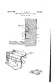
- u Fig.1 is a view showing in fragmentary vertical section ⁇ a concrete wall" and the yadj ayboards of any width and th-e construction of quent insertion of the counter stripy evenr cent parts of a roof and roof covering and flashing, -havingzapplied thereto one form Vof t s roof-flashing sealing ⁇ and lretaining device embodying my invention.
- Fig. 2 isa sectional fragmentary perspective view of the device and the relative posil tions. which its parts assume in respect tothe lroof-hashing.
- I provide ⁇ a device which consists in the mainof a receiving strip Rand a counter flashing-strip;
- strips are formed of suitable sheet metal, the strip R beingv bentlongitudinally along ther medial yline to provide lan upper ply or ⁇ layer 15-and a lower layer' or ply 16, the two layers being ⁇ disposed horizontally when the strip is yin applied position within a wall. That portion of the strip Vat the yinner marginal edge of the plies 15 and 16 is bent upwardly, preferably at right angles to form an upstanding flange 17 provided for they purpose of locking the strip within the wall,
- the lower ply 16 is bent to provide kan'oifset portion 18 in 'order'to space Vthat part'of the to the outerv side ⁇ ofy the offset portion from thelupper ply 15, and to there- 'by form anintervening channel adapted for the receptionof the horizontal portion of the stripis embedded ywithin the concrete ofi( a wall as illustrated in Fig. 1, the aforesaid channel remains open, because the side-walls sition ythereof assumes a vertical position 'as illustrated in'solid linesin Fig. v1. However, this flangeis adapted tobebent tothe inclined position indicated'in dash lines in Fig;
- tlieliange y,19 is ycounter strip C. Even when they receiving loo bent inwardly to form a lip coextensive in length with the flange, and adapted to have Contact with the outer side of the counter strip to effect a liquid tight seal between4 the flange and strip so as to prevent water entering therebetween.
- This flange 19 constitutes an outer vertical ply and, as previously expressed herein, is a continuation of the upper horizontal ply 15.
- the lower horizontal ply 16 is likewise provided with an extension 21 which constitutes an inner vertical ply and exceeds in width that of the outer vertical ply 19.
- the ply 21 at its lower end is extended inwardly and upwardly to form an L-shaped extension 22 adapted to be embedded in the concrete as illustrated in Fig. 1, and to thus coact with the flange 17 in locking the receiving strip firmly within the wall.
- the vertical portion of the extension 22 serves as a stop to prevent the passage of water around and beneath the extension to the outer side of the wall, that is, should the water find its way around the flange 17.
- the counter strip C consists of a sheet of metal having its upper marginal edge bent substantially at right angles to form a flange 23, while its lower edge is bent inwardly at van angle to provide a lip v ⁇ 211.
- the flange and lip are coextensive in length with the strip, and in the applied position of the strip within the receiving strip, the vertical portion of the strip C is disposed between the inner and outer vertical plies 21 and 19, while the flange 23 is disposed in the channel provided between the plies 15 and 16, it being understood that the flange corresponds substantially in width with that of the channel.
- the Vlip 24 is adapted to contact with the vertical -ply 21 so as to form a liquid tight seal between the receiving strip and the ply to prevent the passage of water upwardly from beneath the extension 22.
- the receiving strip R- is secured in position between the wall forms and before that part of the wall projecting above the roof indicated at R is constructed.
- the receiving strip is secured to the inner side of the inner wall form by driving nails through the vertical ply 21 and into the boards forming the inner wall form.
- one or more strands of wire 25 may be connected to the flange 17 and extended upwardly and connected to the inner wall form as illustrated in Fig. 1.
- the concrete may now be poured into the form and preferably in a. manner to insure the passage of the concrete beneath the receiving strip so as to firmly embed the extension 22 therein as well as the flange 17.
- the receiving strip is securely locked within the wall and in such position that the Vertical plies 19 and 21 are disposed to the inner side of the wall.
- the inner wall form can now be readily removed, the boards being pulled from the nails holdingrthe receiving strip, as will be understood. he projecting nails may be clipped flush with the surface of the ply 21, and likewise the ends of the wires 25 cut free of the form boards.
- the plies 19 and 21 are exposed to the inner side of the wall to permit the placement of the counter strip into position.
- a device for retaining land sealing roofflashing comprising a receiving strip adapted to be placed in a wall form and secured in the wall during construction thereof, said' strip comprising a sheet of material folded along a longitudinal line to form superimposed horizontal plies the lower one of which is offset to space it from the other ply and form an intervening channel, said plies at their point of connection being bent upwardly to form a retaining flange, a vertical ply depending from the outer edge of the lower horizontal ply, an inwardly projecting extension at the lower edge of the vertical ply, a second vertical ply depending from the outer edge of the upper horizontal ply, a lip on the lower edge of the outer vertical ply, a counter strip comprising a sheet of material bent along a longitudinal line at its upper marginal edge to form a flange and at its lower edge to form a lip, the vertical portion of the counter strip being disposed between the vertical plies, and the flange within said channel.
- a counter flashing receiver of the type adapted for original embedment in a plastic structure comprising a single piece of sheet material bent to provide a face for fitting against a wall of a mold; a double thickness angle having one leg perpendicular to the face, said leghaving oneY of the component sheets thereof joining'theangle and the face andthe other of fthe component sheets thereof shaped to yprovide a shoulder coextensive in length With the sheetand at the extremity of the leg; a fiat portionparallel to the face and spaced romthe part of the sheet forming the face to provide 'spacev for the insertion of sheet material; a portion of the sheet Ijoining one extremity of the flat portion and the shoulder and spaced from the rst mentioned component sheetlto providel Y space for the insertion of sheetmaterial; and
- an anchor comprising an angle joined to the other extremity of the flat portion by one -leg thereof.
- a receiving strip adapted to be 2o placed ⁇ on a Wall form and secured'in the Wall" duringconstruction thereof, the lower ply of which is offset to space it from the upper ply for at least a portion of its Width to form an intervening channel, aninner vertical ply providing a depending extension of the lower ⁇ horizontal ⁇ ply from a point Where it is spaced yfrom the Yupper horizontaly ply5 said vertical Y ply having means thereon for securing it against outward displacement from the Wall7 and an outer vertical 4ply providing a depending extension of the upper horizontal ply, said vertical plies yco-acting tok dene a vertical channel between the horizontalxplies for the reception of a counter strip, the lower k edge of the outer vertical ply having a seal- Ving lip positioned to engage a counter strip When the latter is inserted Within the channels.
Landscapes
- Engineering & Computer Science (AREA)
- Architecture (AREA)
- Civil Engineering (AREA)
- Structural Engineering (AREA)
- Building Environments (AREA)
Description
April 5, 1932.
ROOF FLASHING RETAINING AND SEALING DEVICE Filed Aug. 26, A 1929 /HMT Clin/1912?' ATTORNEY F. E. CRAMPTON 1,852,955 v Patented .Apre 1932.
Y lFRANK :n.cmiiurroiv, oF Los ANGELES, CALIFORNIA f Roon-,FLASHING RETAINIG AND SEALING DEvioE s Application filed August 26,1929: v serial mj'assai.y v
My kinvention relates todevices for retaining and sealing roof-flashing, and it has particular reference to such devices las are employed in connection with roof-hashing for 6 concrete walls.-
y Devices of this character as heretofore constructed necessitate the use of formboards of prescribed width so that their joints ber kpositioned to permit the extension there- 10 through of the projecting partsof'the device. o
It is apurpose of my invention to provide a' roof-flashing retaining and sealing device,
the receiving strip of which is capable of being contained wholly between the two walls or parts of a wall .form and to the elimination of the necessity ofconstructing the form boards of prescribed widths, there being no part of. the receiving strip projecting from' lthe form, and thus permitting the use of form the wall in the usual manner. V'It is also a purpose of my invention to provide a deviceof the character described having a multiply-receivingystripV and a counterflashing strip adapted to bey inserted between the ply of the receiving strip, and which receiving strip in its association with a wall and roof-'flashing is constructed to maintain vthe plies thereof spaced to allow the subse- A further purpose ofy my invention is the a provision ofv a device having a receivingstrip the inherent construction of. which is such that when placedon a wall during construction thereof andfollowing setting of thev conjcrete, it is locked'inz the wall with suchl a degree of security as` to preventit's removal 'whenremoving'theywall forms, and toprevent seepage of `water therearound and beneathf the roof-ashingrand to thereby efn y i vided with a flangeQO which, in the final' pofectively Aseal the hashing against leakage.
I will describ'evonly one forml of roof-flashing retainingand sealing device embodying my invention, and will then point out the novel features thereof in claims.
a In the accompanyingdrawings:
u Fig.1 is a view showing in fragmentary vertical section `a concrete wall" and the yadj ayboards of any width and th-e construction of quent insertion of the counter stripy evenr cent parts of a roof and roof covering and flashing, -havingzapplied thereto one form Vof t s roof-flashing sealing `and lretaining device embodying my invention. f
Fig. 2 isa sectional fragmentary perspective view of the device and the relative posil tions. which its parts assume in respect tothe lroof-hashing.
l In carrying out my invention, I provide` a device which consists in the mainof a receiving strip Rand a counter flashing-strip;
C. These strips are formed of suitable sheet metal, the strip R beingv bentlongitudinally along ther medial yline to provide lan upper ply or `layer 15-and a lower layer' or ply 16, the two layers being `disposed horizontally when the strip is yin applied position within a wall. That portion of the strip Vat the yinner marginal edge of the plies 15 and 16 is bent upwardly, preferably at right angles to form an upstanding flange 17 provided for they purpose of locking the strip within the wall,
as well as to provide a stop for anyrwater which mayrlnd its wa along the upper surface of the strip,fan so as to prevent: the l water from passing to ythe lower.V side of Sthe strip. The lower ply 16 is bent to provide kan'oifset portion 18 in 'order'to space Vthat part'of the to the outerv side `ofy the offset portion from thelupper ply 15, and to there- 'by form anintervening channel adapted for the receptionof the horizontal portion of the stripis embedded ywithin the concrete ofi( a wall as illustrated in Fig. 1, the aforesaid channel remains open, because the side-walls sition ythereof assumes a vertical position 'as illustrated in'solid linesin Fig. v1. However, this flangeis adapted tobebent tothe inclined position indicated'in dash lines in Fig;
1 in order to permit the insertionof the counter strip as will be Amore fully described hereinafter. The lower edge of tlieliange y,19 is ycounter strip C. Even when they receiving loo bent inwardly to form a lip coextensive in length with the flange, and adapted to have Contact with the outer side of the counter strip to effect a liquid tight seal between4 the flange and strip so as to prevent water entering therebetween.
This flange 19 constitutes an outer vertical ply and, as previously expressed herein, is a continuation of the upper horizontal ply 15. The lower horizontal ply 16 is likewise provided with an extension 21 which constitutes an inner vertical ply and exceeds in width that of the outer vertical ply 19. The ply 21 at its lower end is extended inwardly and upwardly to form an L-shaped extension 22 adapted to be embedded in the concrete as illustrated in Fig. 1, and to thus coact with the flange 17 in locking the receiving strip firmly within the wall. The vertical portion of the extension 22 serves as a stop to prevent the passage of water around and beneath the extension to the outer side of the wall, that is, should the water find its way around the flange 17.
The counter strip C consists of a sheet of metal having its upper marginal edge bent substantially at right angles to form a flange 23, while its lower edge is bent inwardly at van angle to provide a lip v`211. The flange and lip are coextensive in length with the strip, and in the applied position of the strip within the receiving strip, the vertical portion of the strip C is disposed between the inner and outer vertical plies 21 and 19, while the flange 23 is disposed in the channel provided between the plies 15 and 16, it being understood that the flange corresponds substantially in width with that of the channel. The Vlip 24 is adapted to contact with the vertical -ply 21 so as to form a liquid tight seal between the receiving strip and the ply to prevent the passage of water upwardly from beneath the extension 22.
In actual practice, the receiving strip R- is secured in position between the wall forms and before that part of the wall projecting above the roof indicated at R is constructed. The receiving strip is secured to the inner side of the inner wall form by driving nails through the vertical ply 21 and into the boards forming the inner wall form. To sustain the receiving strip in proper position, particularly when pouring the fluid concrete into the wall form, one or more strands of wire 25 may be connected to the flange 17 and extended upwardly and connected to the inner wall form as illustrated in Fig. 1. With the receiving strip secured as described, the concrete may now be poured into the form and preferably in a. manner to insure the passage of the concrete beneath the receiving strip so as to firmly embed the extension 22 therein as well as the flange 17. Once the concrete is set, the receiving strip is securely locked within the wall and in such position that the Vertical plies 19 and 21 are disposed to the inner side of the wall. The inner wall form can now be readily removed, the boards being pulled from the nails holdingrthe receiving strip, as will be understood. he projecting nails may be clipped flush with the surface of the ply 21, and likewise the ends of the wires 25 cut free of the form boards. Thus, with the form boards removed, the plies 19 and 21 are exposed to the inner side of the wall to permit the placement of the counter strip into position. In applying the counter strip, it is of course necessary to bend the ply 19 outwardly to the dotted line position, the counter strip being placed to the outer side of the roof flashing indicated at 26 which is extended between the counter strip and the verticalply 21. The lip 24 bears against the roof flashing as illustrated in Fig. 1 and thus holds the latter snugly against the inner side of the wall so as to seal the roof flashing against the passage of water therebeneath. Once the counter strip is applied, the ply 19 is bent back to normal position so that its lip 20 engages the outer side of the counter strip to form a seal against the passage of water upwardly between the two plies.
Although I have herein shown and described only one form of roof-flashing retaining and sealing device embodying my invention, it is to be understood that various changes and modifications may be made herein without departing from the spirit of the invention and the spirit and scope of the appended claims.
I claim:
1. A device for retaining land sealing roofflashing, comprising a receiving strip adapted to be placed in a wall form and secured in the wall during construction thereof, said' strip comprising a sheet of material folded along a longitudinal line to form superimposed horizontal plies the lower one of which is offset to space it from the other ply and form an intervening channel, said plies at their point of connection being bent upwardly to form a retaining flange, a vertical ply depending from the outer edge of the lower horizontal ply, an inwardly projecting extension at the lower edge of the vertical ply, a second vertical ply depending from the outer edge of the upper horizontal ply, a lip on the lower edge of the outer vertical ply, a counter strip comprising a sheet of material bent along a longitudinal line at its upper marginal edge to form a flange and at its lower edge to form a lip, the vertical portion of the counter strip being disposed between the vertical plies, and the flange within said channel. f
2. A counter flashing receiver of the type adapted for original embedment in a plastic structure, said receiver comprising a single piece of sheet material bent to provide a face for fitting against a wall of a mold; a double thickness angle having one leg perpendicular to the face, said leghaving oneY of the component sheets thereof joining'theangle and the face andthe other of fthe component sheets thereof shaped to yprovide a shoulder coextensive in length With the sheetand at the extremity of the leg; a fiat portionparallel to the face and spaced romthe part of the sheet forming the face to provide 'spacev for the insertion of sheet material; a portion of the sheet Ijoining one extremity of the flat portion and the shoulder and spaced from the rst mentioned component sheetlto providel Y space for the insertion of sheetmaterial; and
an anchor comprising an angle joined to the other extremity of the flat portion by one -leg thereof. i f
3. In a device for retaining and sealing f 4roof flashing, a receiving strip adapted to be 2o placed `on a Wall form and secured'in the Wall" duringconstruction thereof, the lower ply of which is offset to space it from the upper ply for at least a portion of its Width to form an intervening channel, aninner vertical ply providing a depending extension of the lower` horizontal `ply from a point Where it is spaced yfrom the Yupper horizontaly ply5 said vertical Y ply having means thereon for securing it against outward displacement from the Wall7 and an outer vertical 4ply providing a depending extension of the upper horizontal ply, said vertical plies yco-acting tok dene a vertical channel between the horizontalxplies for the reception of a counter strip, the lower k edge of the outer vertical ply having a seal- Ving lip positioned to engage a counter strip When the latter is inserted Within the channels. l
FRANK E. CRAMPTON.
Priority Applications (1)
| Application Number | Priority Date | Filing Date | Title |
|---|---|---|---|
| US388521A US1852955A (en) | 1929-08-26 | 1929-08-26 | Roof-flashing retaining and sealing device |
Applications Claiming Priority (1)
| Application Number | Priority Date | Filing Date | Title |
|---|---|---|---|
| US388521A US1852955A (en) | 1929-08-26 | 1929-08-26 | Roof-flashing retaining and sealing device |
Publications (1)
| Publication Number | Publication Date |
|---|---|
| US1852955A true US1852955A (en) | 1932-04-05 |
Family
ID=23534442
Family Applications (1)
| Application Number | Title | Priority Date | Filing Date |
|---|---|---|---|
| US388521A Expired - Lifetime US1852955A (en) | 1929-08-26 | 1929-08-26 | Roof-flashing retaining and sealing device |
Country Status (1)
| Country | Link |
|---|---|
| US (1) | US1852955A (en) |
Cited By (3)
| Publication number | Priority date | Publication date | Assignee | Title |
|---|---|---|---|---|
| US2441676A (en) * | 1946-04-16 | 1948-05-18 | David D Smith | Flashing |
| US2664177A (en) * | 1947-10-10 | 1953-12-29 | Andrew B Hammitt | Flashing construction |
| US3793795A (en) * | 1971-09-23 | 1974-02-26 | C Annand | Waterproofing receiver |
-
1929
- 1929-08-26 US US388521A patent/US1852955A/en not_active Expired - Lifetime
Cited By (3)
| Publication number | Priority date | Publication date | Assignee | Title |
|---|---|---|---|---|
| US2441676A (en) * | 1946-04-16 | 1948-05-18 | David D Smith | Flashing |
| US2664177A (en) * | 1947-10-10 | 1953-12-29 | Andrew B Hammitt | Flashing construction |
| US3793795A (en) * | 1971-09-23 | 1974-02-26 | C Annand | Waterproofing receiver |
Similar Documents
| Publication | Publication Date | Title |
|---|---|---|
| US3319384A (en) | Construction for extruded reglets | |
| US5371980A (en) | Shower liner | |
| US2226886A (en) | Reglet | |
| US1852955A (en) | Roof-flashing retaining and sealing device | |
| US2054308A (en) | Sealing collar | |
| US2219992A (en) | Reglet and counterflashing securing member | |
| US5619827A (en) | Roof edge flashing and anchoring system | |
| US2168204A (en) | Interlocking flashing plate | |
| US3132445A (en) | Plastic gravel stop and fascia | |
| US2112332A (en) | Flashing block | |
| US2003503A (en) | Roofing or surfacing material | |
| US1338262A (en) | Roof | |
| US2360031A (en) | Roof flashing | |
| US1231711A (en) | Wall construction. | |
| US2255279A (en) | Flashing | |
| US1958622A (en) | Reglet and counter flashing | |
| US2807222A (en) | Flashing reglet assembly | |
| US1436945A (en) | Shingle | |
| US1625688A (en) | Roof-flashing sealing and retaining device | |
| US1935829A (en) | Flashing | |
| US1105422A (en) | Combination base and counter flashing. | |
| US1884259A (en) | Flashing for roofs | |
| US2032967A (en) | Roof edging strip | |
| US2252834A (en) | Roof flashing | |
| US2272310A (en) | Asphalt seal for metallic window frames |