US1852895A - Paper sack holder - Google Patents
Paper sack holder Download PDFInfo
- Publication number
- US1852895A US1852895A US453647A US45364730A US1852895A US 1852895 A US1852895 A US 1852895A US 453647 A US453647 A US 453647A US 45364730 A US45364730 A US 45364730A US 1852895 A US1852895 A US 1852895A
- Authority
- US
- United States
- Prior art keywords
- bags
- paper sack
- sack holder
- trough
- paper
- Prior art date
- Legal status (The legal status is an assumption and is not a legal conclusion. Google has not performed a legal analysis and makes no representation as to the accuracy of the status listed.)
- Expired - Lifetime
Links
- 238000005192 partition Methods 0.000 description 8
- 238000012986 modification Methods 0.000 description 4
- 230000004048 modification Effects 0.000 description 4
- 238000010276 construction Methods 0.000 description 2
- 238000004873 anchoring Methods 0.000 description 1
- 230000015572 biosynthetic process Effects 0.000 description 1
- 150000001768 cations Chemical class 0.000 description 1
- 238000012423 maintenance Methods 0.000 description 1
- 239000002184 metal Substances 0.000 description 1
- 238000000034 method Methods 0.000 description 1
Images
Classifications
-
- A—HUMAN NECESSITIES
- A47—FURNITURE; DOMESTIC ARTICLES OR APPLIANCES; COFFEE MILLS; SPICE MILLS; SUCTION CLEANERS IN GENERAL
- A47F—SPECIAL FURNITURE, FITTINGS, OR ACCESSORIES FOR SHOPS, STOREHOUSES, BARS, RESTAURANTS OR THE LIKE; PAYING COUNTERS
- A47F13/00—Shop or like accessories
- A47F13/08—Hand implements, e.g. grocers' scoops, ladles, paper-bag holders
- A47F13/085—Shopping-bag holders
-
- Y—GENERAL TAGGING OF NEW TECHNOLOGICAL DEVELOPMENTS; GENERAL TAGGING OF CROSS-SECTIONAL TECHNOLOGIES SPANNING OVER SEVERAL SECTIONS OF THE IPC; TECHNICAL SUBJECTS COVERED BY FORMER USPC CROSS-REFERENCE ART COLLECTIONS [XRACs] AND DIGESTS
- Y10—TECHNICAL SUBJECTS COVERED BY FORMER USPC
- Y10T—TECHNICAL SUBJECTS COVERED BY FORMER US CLASSIFICATION
- Y10T24/00—Buckles, buttons, clasps, etc.
- Y10T24/20—Paper fastener
- Y10T24/202—Resiliently biased
- Y10T24/205—One piece
- Y10T24/206—Mounted on support means
Definitions
- I tothe-r ends fof the"partition:mrmber5.11.v .i
- eyes or "other*-forms offa steningf vention consists of a support of this char-such as-indicated at'13,-may befarrangeclat acter includinga trough to accommodate intervals/uponthe upper edgeof-the' partithe bottoms of'the bags.
- the tion member 11- to adequately-"support;
- the Another object of the invention contemholder"constructioneabove:the counters and 19 plates the provision and arrangement of 'eye'level of-storeclerks ofaverage heighfi retaining means for the bags whereby the 'The retaining means comprises@substanlatter will be disposed in proper position: "tially inverted u-shaped yokes 14% disposed within the trough.
- 3 of-the :drawingsy-that isyverticallywithin the invention further consists of the followy each ⁇ of the-pockets;- formed-:in theztrough ing novel features and details of construe-t' likereceptacleandfiush against theopposed tion, to be hereinafter more fully described," ,”sl'des of the: partition :member.-
- Figure 6 is a front elevation of the modifi-, Tl le'p'late members are preferablyqdisposed cation.
- 7adj-acent the ends oflthe companion retain- Figure 7 is a fragmentary rear elevation: ingelementswhereby the invention'wi'll' beof the modification illustrating the manallowed tofunctionunrestrictedby fthepresner and means of anchoring the retaining ence" of the platemember 16.. Itmay b'efdemeans thereon.
- the difi'erence in construction tion projecting within the receptacle is pro jected centrally of the longitudinal axis thereof whereby pockets of even dimensions will be formed upon opposite sides thereof 0 within the trough-like receptacle.
- the endsidingbetween the preferred and modified forms of our invention primarily resides in the method and manner of securing the extremities of the substantially inverted U -shaped forms of retaining elements Mi Inasmuch as the modification is to be constructed of metal throughout, the rear walls of the receptacles are provided with spaced openings 19 through which portions of the spring loops are first outwardly projected,
- the bags are to be arranged in the manner shown in dotted lines in Figure 3 of the drawings whereby the flap formed by the folding of the bag bottoms against the sides of the bags proper will provide convenient finger holds or finger engaging portions by means of which the store clerk may readily remove the bags even as against the tension exercised thereupon by the retaining elements 14:.
- a holder for a series of groups of paper bags of different sizes comprising a partition member, a trough at the lower edge of the partition member and running the full length thereof, a series of spring yoke members of 50 different transverse breadth secured at their lower ends to the partition member at points below the upper edge of the trough said yoke members having coils standing out from the partition member and located in the trough and dividing the trough into compartments.
Landscapes
- Purses, Travelling Bags, Baskets, Or Suitcases (AREA)
Description
April 5, 1-932.
J. J. PETRICK ET AL I PAPER SACK HOLDER 2 Sheets-Sheet' 1 Filed May 19, 1930 l: I NVENTQR ATTORN EY April 5, 1932.
J.IJ.VPETRICK ETAL 1,852,895
PAPER SACK HOLDER Filed May 19, 1930 2 Sheets-Sheet 2 INVENTOR ATTORNEY Patented. Apr. 5, 1932:
UNITE STA res J'QHIN J. PETRICK AND JAMES C. PETRICKZOF QPLAINZEIE LD;'EWISGONSIN PAPER SACK Holman Application filed May 19, 1930. Serial No. 453,647.
This invention relates, to certain new and" :wallsof-thetrongh=like receptacle1are--prouseful improvements, in supports or holders sided with extensions 12 upwardlyand inof a type designed forfthe maintenance of'-'*wardly projected-therefrom-- and -secured paper bags and thelike. I tothe-r ends fof the"partition:mrmber5.11.v .i
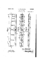
5 One of-the principal objects of the in- Screw. eyes or "other*-forms offa steningf vention consists ofa support of this char-such as-indicated at'13,-may befarrangeclat acter includinga trough to accommodate intervals/uponthe upper edgeof-the' partithe bottoms of'the bags. tion member, 11- to adequately-"support; the Another object of the invention contemholder"constructioneabove:the counters and 19 plates the provision and arrangement of 'eye'level of-storeclerks ofaverage heighfi retaining means for the bags whereby the 'The retaining means comprises@substanlatter will be disposed in proper position: "tially inverted u-shaped yokes 14% disposed within the trough. in the manner suggested Figures 1" and With the above and other objects in view, 3 of-the :drawingsy-that isyverticallywithin the invention further consists of the followy each} of the-pockets;- formed-:in theztrough ing novel features and details of construe-t' likereceptacleandfiush against theopposed tion, to be hereinafter more fully described," ,"sl'des of the: partition :member.- The "legs illustrated in the accompanying drawings or dependencies of -the: substantially "inand pointed out in the appended claim. fiver-ted Ur-shaped *retaining elements 14 form In the drawings: :"tspringrloops 1-5 having the-terminals there 70 Figure l is a front elevation of the pres of rigidlysecured-against theadjacentsur ent invention partly broken away to illusface of the partition member 'wherebyathe trate the relative arrangement of the retainj uppermost portions of that-retaining. elements will be sprung *toward 'saidpartition ing means. v
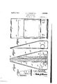
Figure 2 is a topplan view of the inven- VmemberJ-I 'Plateimem-bers 16 arranged'at in 1 1 =--ter-vals,;.-up oi1' diametrically oppositefsides of Figure 3 is a vertical sectional view taken 1 the; partition member and providediwith through the invention, pockets" orchannels" l7"*for the accommoda- Figure 4 is a top plan view of a modified tion ofv the ends or terminals ofther'spring 7 form of our invention; loops lo ar'eheld together byy'means of' 801 Figure 5 is a vertical sectional view taken ;fasten1ng=l8 common to the oppositelymosithrough the modification. "."itione d plate members. Figure 6 is a front elevation of the modifi-, Tl le'p'late members are preferablyqdisposed cation. 7adj-acent the ends oflthe companion retain- Figure 7 is a fragmentary rear elevation: ingelementswhereby the invention'wi'll' beof the modification illustrating the manallowed tofunctionunrestrictedby fthepresner and means of anchoring the retaining ence" of the platemember 16.. Itmay b'efdemeans thereon. sirofus, in someinstances toarrangethe bagv Referring tothe drawings in detail where-i holdenconstrimtiQn beneath tlIBStOI'QZCOIIHtEI 40 in like characters of referencs denote corre- "but thedOubIefOrm of bagholderconstruc sponding parts, the reference character 10""tion can not be employed for-thereasonthat indicates generally a receptacle of troughthelclerklwillbe unable to have access'to the like formation having rightangularly disothensideinasmuch asit will be either hung posed side and bottom walls respectively. A beneaththecounter orl'aid upon a shelf therepartition member 11 having its lower porbeneath. The difi'erence in construction tion projecting within the receptacle is pro jected centrally of the longitudinal axis thereof whereby pockets of even dimensions will be formed upon opposite sides thereof 0 within the trough-like receptacle. The endsidingbetween the preferred and modified forms of our invention primarily resides in the method and manner of securing the extremities of the substantially inverted U -shaped forms of retaining elements Mi Inasmuch as the modification is to be constructed of metal throughout, the rear walls of the receptacles are provided with spaced openings 19 through which portions of the spring loops are first outwardly projected,
extended for appreciable distances downwardly and against the other surface of the rear wall, inwardly through the lowermost of the openings 19 and then fiat against the inner surface of the rear wall in the manner shown in Figure 5 of the drawings. The structural details are the same in the modifications of our invention shown in Figures 4 and 6 of the drawings; the only difference being the pro- 15 portions thereof.
As will be noted the various forms of our invention may be constructed and arranged in such manner that suitable numbers of the various sizes of bags may be supported in po- "1 sition for immediate dispensing.
The bags are to be arranged in the manner shown in dotted lines in Figure 3 of the drawings whereby the flap formed by the folding of the bag bottoms against the sides of the bags proper will provide convenient finger holds or finger engaging portions by means of which the store clerk may readily remove the bags even as against the tension exercised thereupon by the retaining elements 14:. In-
' asniuch as the direction of pull upon the removed bag is in a direction toward the bottom wall of the receptacle, it is to be noted that the bottoms or at least the edges of the bottoms of each of the bags will be forced against the bottom of the receptacle whereby the initial disposition of the packet of bags will be preserved.
The invention is susceptible of various changes in its form, proportions and minor details of construction, and the right is herein reserved to make such changes as properly fall within the scope of the appended claim.
Having described the invention, what is claimed is:
46 A holder for a series of groups of paper bags of different sizes comprising a partition member, a trough at the lower edge of the partition member and running the full length thereof, a series of spring yoke members of 50 different transverse breadth secured at their lower ends to the partition member at points below the upper edge of the trough said yoke members having coils standing out from the partition member and located in the trough and dividing the trough into compartments.
In testimony whereof we affix our signatures.
JOHN J. PETRICK.
JAMES C. PETR-ICK.
Priority Applications (1)
| Application Number | Priority Date | Filing Date | Title |
|---|---|---|---|
| US453647A US1852895A (en) | 1930-05-19 | 1930-05-19 | Paper sack holder |
Applications Claiming Priority (1)
| Application Number | Priority Date | Filing Date | Title |
|---|---|---|---|
| US453647A US1852895A (en) | 1930-05-19 | 1930-05-19 | Paper sack holder |
Publications (1)
| Publication Number | Publication Date |
|---|---|
| US1852895A true US1852895A (en) | 1932-04-05 |
Family
ID=23801468
Family Applications (1)
| Application Number | Title | Priority Date | Filing Date |
|---|---|---|---|
| US453647A Expired - Lifetime US1852895A (en) | 1930-05-19 | 1930-05-19 | Paper sack holder |
Country Status (1)
| Country | Link |
|---|---|
| US (1) | US1852895A (en) |
-
1930
- 1930-05-19 US US453647A patent/US1852895A/en not_active Expired - Lifetime
Similar Documents
| Publication | Publication Date | Title |
|---|---|---|
| US2289751A (en) | Display rack | |
| US2684766A (en) | Stackable trays and holder for same | |
| US2198138A (en) | Holder for medicinal charts | |
| US2967611A (en) | Carton for merchandising display cards | |
| US1968880A (en) | Article display device | |
| US1852895A (en) | Paper sack holder | |
| US1966676A (en) | Counter dispensing device | |
| US2044231A (en) | Bag dispensing cabinet | |
| US1832158A (en) | Shelf box | |
| US2023150A (en) | Device for displaying containers | |
| US2397549A (en) | Portable bottle carrier | |
| US1664245A (en) | Tool box | |
| US1713185A (en) | Bag holder | |
| US1706307A (en) | Bag holder and display rack | |
| US2211666A (en) | Tag holder | |
| US2256985A (en) | Package | |
| US2186343A (en) | Retainer for paper bags | |
| US1640084A (en) | Bag holder | |
| US1365689A (en) | Dispensing appliance | |
| US1682069A (en) | Shipping and display box | |
| US2198183A (en) | Vertical card index or system | |
| US2165107A (en) | Package for dispensing paper sheets | |
| US1938970A (en) | Display rack | |
| US2091742A (en) | Paint brush holder | |
| US1568515A (en) | Paper-bag rack |