US1852890A - Engine - Google Patents
Engine Download PDFInfo
- Publication number
- US1852890A US1852890A US434133A US43413330A US1852890A US 1852890 A US1852890 A US 1852890A US 434133 A US434133 A US 434133A US 43413330 A US43413330 A US 43413330A US 1852890 A US1852890 A US 1852890A
- Authority
- US
- United States
- Prior art keywords
- piston
- engine
- crank
- pistons
- cylinder
- Prior art date
- Legal status (The legal status is an assumption and is not a legal conclusion. Google has not performed a legal analysis and makes no representation as to the accuracy of the status listed.)
- Expired - Lifetime
Links
- 230000006835 compression Effects 0.000 description 2
- 238000007906 compression Methods 0.000 description 2
- 241001591024 Samea Species 0.000 description 1
- 238000002485 combustion reaction Methods 0.000 description 1
- 238000003280 down draw process Methods 0.000 description 1
- 238000004880 explosion Methods 0.000 description 1
- 238000004519 manufacturing process Methods 0.000 description 1
- 239000004576 sand Substances 0.000 description 1
Images
Classifications
-
- F—MECHANICAL ENGINEERING; LIGHTING; HEATING; WEAPONS; BLASTING
- F02—COMBUSTION ENGINES; HOT-GAS OR COMBUSTION-PRODUCT ENGINE PLANTS
- F02B—INTERNAL-COMBUSTION PISTON ENGINES; COMBUSTION ENGINES IN GENERAL
- F02B75/00—Other engines
- F02B75/02—Engines characterised by their cycles, e.g. six-stroke
-
- F—MECHANICAL ENGINEERING; LIGHTING; HEATING; WEAPONS; BLASTING
- F02—COMBUSTION ENGINES; HOT-GAS OR COMBUSTION-PRODUCT ENGINE PLANTS
- F02B—INTERNAL-COMBUSTION PISTON ENGINES; COMBUSTION ENGINES IN GENERAL
- F02B1/00—Engines characterised by fuel-air mixture compression
-
- F—MECHANICAL ENGINEERING; LIGHTING; HEATING; WEAPONS; BLASTING
- F02—COMBUSTION ENGINES; HOT-GAS OR COMBUSTION-PRODUCT ENGINE PLANTS
- F02B—INTERNAL-COMBUSTION PISTON ENGINES; COMBUSTION ENGINES IN GENERAL
- F02B2700/00—Measures relating to the combustion process without indication of the kind of fuel or with more than one fuel
- F02B2700/02—Four stroke engines
Definitions
- This invention relates yto improvements in engines.
- the principal object of thisinvention is to produce an engine having a power stroke one exhaust and two intake strokes of the pistons for each revolution of the crank shaft.
- Another object is to produce an engine which will function in the same manner as an ordinary internal combustion engine, nainely by causing an explosion resulting in a power stroke and then exhausting the exploded gas to the atmosphere.
- a ⁇ further object is to vproduce a devlceV Which is relatively ⁇ inexpensive to manufacture.
- a still further kobject is to produce an engine which is positive in operation and therefore one which will function in proper sequence.v
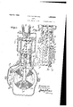
- Fgure 1 is a vertical cross section of my engine, f y
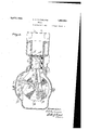
- Figure 2 is a fragmentary vertical cross section taken at right angles to that of Figure 1, in'order to show the crank mechanism, and f Figure 3 is a view similar to Figure 1 but showing the pistons at substantially the bottom of the power stroke.
- the nu- ⁇ meral 5 designates the customary crank case upon which is secured a cylinder 6 having a cylinderhead' 7 vWithinwhichl the exhaust valve ⁇ 8 and intake valve 9 are positioned.
- l Movable within the cylinder 6 is a piston'll connected through the medium of connecting rods 12 and 13 to the crank of a crank shaft 14 (see v Figure 2).
- cam discs 16 and 17 Secured to the crank shaft 14 are cam discs 16 and 17.
- the cam disc 16 has cam grooves 18 formed therein, in which a roller 19 carried upon an arm 21 is pivoted as at 22 to the side 4of the crank casing 5.
- link 23 connects the free end of the arm 21 to a ⁇ bell-crank 24'pivoted as at 26 to the crank case 5'.
- kThegfree endy of the. bell-crankpro-7 jects between the connecting'rods 112p ⁇ and 13 and is connected by'a link 27 tothe lowerend 55 of aypiston rod'28, .whichwpiston rod passes i throughthe pistony 11 land carries"y an auxilf. i Vietnamesey piston'29 upon its upper end; v i' A number of byfpasses 31 is formed inthe f g cylinder and at a .point substantially Leven' 1 6o with the bottom oi' A,the power stroke.
- crankshaft 14 When the crank shaftapf l preaches the 1 point .substantially yforty-five degrees A,before lower dead center E the .roller 19 will'approachaposition,inthe cam groove 18 ywhich will result in theauxiliary piston leaving .the main ⁇ piston and starting backwardly in an upward direction. At the sameA time the lever 33 riding upon the cam 17 will open the exhaust valve Sand the inlet rvalve .ii 32. VAs a consequence the burned gas ywill be .85. exhausted and a fresh chargeof gas will be drawn ⁇ inat a point between the 'auxiliaryk piston 291V and ythe rnaingpistonr 11.
- the cam l7 ⁇ Upon reaching .the lower dead center, the cam l7 ⁇ operates to close ythe ,exhaustl valve and the.l intake valve 32 and Lthe intake valve 9 is opened.
- the auxiliary piston now starts to travel down drawing in a first charge through the valve k9, at'thesame time compresses the. charge confined between the two pistons..
- a cylinder a crank shaft positioned beneath said cylinder, a piston movable in said cylinder and connected to said crank shaft, a cam secured to said crank shaft, a second piston mounted in said cylinder, a rod extending thru said first mentioned piston and connected'to said second mentioned piston, levers interposed between said rod and said cam whereby the movement of said second mentioned piston may be varied with relation to the movement of said iirsty mentioned piston, a.
Landscapes
- Engineering & Computer Science (AREA)
- Chemical & Material Sciences (AREA)
- Combustion & Propulsion (AREA)
- Mechanical Engineering (AREA)
- General Engineering & Computer Science (AREA)
- Valve-Gear Or Valve Arrangements (AREA)
- Transmission Devices (AREA)
Description
April 5, 1932. A. D. MacFARLANE ENGINE 2 Sheets-Sheet 2 Filed MarOh 7, 1930 Figs.
Th1/@J9 on /MMC Patented Apr. '5,1932' i.
ENr oiFElc-E .ARTHUR D. MACFARLANE, OIE" LOS ANGELES,-CALIFORNIA ENGINE vApplication mea 'March 7,-
This invention relates yto improvements in engines.
The principal object of thisinvention is to produce an engine having a power stroke one exhaust and two intake strokes of the pistons for each revolution of the crank shaft.
Another object is to produce an engine which will function in the same manner as an ordinary internal combustion engine, nainely by causing an explosion resulting in a power stroke and then exhausting the exploded gas to the atmosphere.
A` further object is to vproduce a devlceV Which is relatively` inexpensive to manufacture.
A still further kobject is to produce an engine which is positive in operation and therefore one which will function in proper sequence.v
Other objects and advantages will be ap,- parent during the course of the following description.
Inthe accompanying drawings forming a part of this specication and in which like numeralsare employed to .designate like parts throughout the same,
Fgure 1 is a vertical cross section of my engine, f y
Figure 2 is a fragmentary vertical cross section taken at right angles to that of Figure 1, in'order to show the crank mechanism, and f Figure 3 is a view similar to Figure 1 but showing the pistons at substantially the bottom of the power stroke.
In the accompanying` drawings wherein for the purpose `of illustration is shown a preerred embodimentof my invention, the nu-` meral 5 designates the customary crank case upon which is secured a cylinder 6 having a cylinderhead' 7 vWithinwhichl the exhaust valve `8 and intake valve 9 are positioned.l Movable within the cylinder 6 is a piston'll connected through the medium of connecting rods 12 and 13 to the crank of a crank shaft 14 (see vFigure 2)..v Secured to the crank shaft 14 are cam discs 16 and 17. The cam disc 16 has cam grooves 18 formed therein, in which a roller 19 carried upon an arm 21 is pivoted as at 22 to the side 4of the crank casing 5. A
'piston the charge compressed: therebetween 1930,. Serial No. 434,133.
link 23 connects the free end of the arm 21 to a` bell-crank 24'pivoted as at 26 to the crank case 5'. kThegfree endy of the. bell-crankpro-7 jects between the connecting'rods 112p` and 13 and is connected by'a link 27 tothe lowerend 55 of aypiston rod'28, .whichwpiston rod passes i throughthe pistony 11 land carries"y an auxilf. i iary piston'29 upon its upper end; v i' A number of byfpasses 31 is formed inthe f g cylinder and at a .point substantially Leven' 1 6o with the bottom oi' A,the power stroke. `With#l in one of these by-passes is positioned van' in? letvalve 32 whichfoperates s'muultaneously' y with ythe exhaust valve .8. These-valves are;` operated through a lever 33 traveling yon the 65 ca1n17. u Y Y f Y' I The operationof myengine is as followsf* Beginning at the end fof the compression stroke, -a spark `occurs in the compression chamber above the pistons and ignitesthe gas 7o `compressed therein and as at thistme the` auxiliary pistonuremains upon the main piston. y. The' result would be that both pistons will ftravel downwardly thus transmitting p power .through the crank 12 .and 13 to. the crankshaft 14. When the crank shaftapf l preaches the 1 point .substantially yforty-five degrees A,before lower dead center E the .roller 19 will'approachaposition,inthe cam groove 18 ywhich will result in theauxiliary piston leaving .the main `piston and starting backwardly in an upward direction. At the sameA time the lever 33 riding upon the cam 17 will open the exhaust valve Sand the inlet rvalve .ii 32. VAs a consequence the burned gas ywill be .85. exhausted and a fresh chargeof gas will be drawn` inat a point between the 'auxiliaryk piston 291V and ythe rnaingpistonr 11. Upon reaching .the lower dead center, the cam l7` operates to close ythe ,exhaustl valve and the.l intake valve 32 and Lthe intake valve 9 is opened. The auxiliary piston now starts to travel down drawing in a first charge through the valve k9, at'thesame time compresses the. charge confined between the two pistons..
At` thirty-,five degrees beyond lower dead n center'the upperintake .valve closes and as. the auxiliary piston approachesy the main will pass around the by-'pass 31 and enterfl into the cylinder at a point above the pistons. This double charge is now compressed by the upper movement of the pistons and when the pistons arrive at substantially top dead 5 center a spark again occurs and the cycle has been completed.
It is to be understood that the form of my invention herewith shown and described is to be taken as a preferred example of the same and that various changes relative to the materia-l, size, shape and arrangement of arts may be resorted to Without departing rom the spirit of the invention or the scope of the sub]oined claim. Having thus described my invention, I
claim In a device of the character described, a cylinder, a crank shaft positioned beneath said cylinder, a piston movable in said cylinder and connected to said crank shaft, a cam secured to said crank shaft, a second piston mounted in said cylinder, a rod extending thru said first mentioned piston and connected'to said second mentioned piston, levers interposed between said rod and said cam whereby the movement of said second mentioned piston may be varied with relation to the movement of said iirsty mentioned piston, a. by-pass formed in said cylinder at a point adjacent the lower most point of movement of said pistons, an intake valve positioned in said by-pass, an intake valve positioned above sa1d second mentioned piston, an exhaust valve positoned above said second mentioned piston, means for opening said first mentioned intake valve and said exhaust valve simultaneously, means for opening said second mentioned intake valve whereby a charge of'gas may be delivered above said second mentioned piston to be mixed with a charge admitted thru said first mentioned intake valve in the manner and for the purpose described.
In testimon whereof I aiiix my signature.
AR HUB D. MAoFAR-LANE.
Priority Applications (1)
| Application Number | Priority Date | Filing Date | Title |
|---|---|---|---|
| US434133A US1852890A (en) | 1930-03-07 | 1930-03-07 | Engine |
Applications Claiming Priority (1)
| Application Number | Priority Date | Filing Date | Title |
|---|---|---|---|
| US434133A US1852890A (en) | 1930-03-07 | 1930-03-07 | Engine |
Publications (1)
| Publication Number | Publication Date |
|---|---|
| US1852890A true US1852890A (en) | 1932-04-05 |
Family
ID=23722939
Family Applications (1)
| Application Number | Title | Priority Date | Filing Date |
|---|---|---|---|
| US434133A Expired - Lifetime US1852890A (en) | 1930-03-07 | 1930-03-07 | Engine |
Country Status (1)
| Country | Link |
|---|---|
| US (1) | US1852890A (en) |
Cited By (6)
| Publication number | Priority date | Publication date | Assignee | Title |
|---|---|---|---|---|
| US2962010A (en) * | 1958-09-02 | 1960-11-29 | Alwin B Newton | Internal combustion engine |
| US5243938A (en) * | 1992-07-30 | 1993-09-14 | Yan Miin J | Differential stroke internal combustion engine |
| WO2013177321A1 (en) * | 2012-05-22 | 2013-11-28 | Yan Engines, Inc. | Piston-train guide apparatus and method |
| RU2559421C2 (en) * | 2010-03-31 | 2015-08-10 | Ян Энджинз, Инк. | Perfected ice with differential stroke of piston |
| US9366179B2 (en) | 2012-05-22 | 2016-06-14 | Yan Engines, Inc. | Linear actuation for continuously variable-stroke cycle engine |
| WO2017168158A1 (en) * | 2016-04-01 | 2017-10-05 | Yan Engines, Ltd. | Guide cam assembly for differential and variable stroke cycle engines |
-
1930
- 1930-03-07 US US434133A patent/US1852890A/en not_active Expired - Lifetime
Cited By (14)
| Publication number | Priority date | Publication date | Assignee | Title |
|---|---|---|---|---|
| US2962010A (en) * | 1958-09-02 | 1960-11-29 | Alwin B Newton | Internal combustion engine |
| US5243938A (en) * | 1992-07-30 | 1993-09-14 | Yan Miin J | Differential stroke internal combustion engine |
| RU2559421C2 (en) * | 2010-03-31 | 2015-08-10 | Ян Энджинз, Инк. | Perfected ice with differential stroke of piston |
| US8851031B2 (en) | 2012-05-22 | 2014-10-07 | Yan Engines, Inc. | Piston-train guide apparatus and method |
| CN104379904A (en) * | 2012-05-22 | 2015-02-25 | 颜氏发动机有限公司 | Piston-train guide apparatus and method |
| JP2015518936A (en) * | 2012-05-22 | 2015-07-06 | ヤン エンジンズ インコーポレイテッド | Piston-train guide apparatus and method |
| WO2013177321A1 (en) * | 2012-05-22 | 2013-11-28 | Yan Engines, Inc. | Piston-train guide apparatus and method |
| KR101567271B1 (en) | 2012-05-22 | 2015-11-06 | 얀 엔진스, 인크. | Piston-train guide apparatus and method |
| US9366179B2 (en) | 2012-05-22 | 2016-06-14 | Yan Engines, Inc. | Linear actuation for continuously variable-stroke cycle engine |
| CN104379904B (en) * | 2012-05-22 | 2016-09-14 | 颜氏发动机有限公司 | Piston system guide device and method |
| WO2017168158A1 (en) * | 2016-04-01 | 2017-10-05 | Yan Engines, Ltd. | Guide cam assembly for differential and variable stroke cycle engines |
| CN109477428A (en) * | 2016-04-01 | 2019-03-15 | 颜氏发动机股份有限公司 | Guided cam assemblies for differential and variable stroke cycle engines |
| RU2698376C1 (en) * | 2016-04-01 | 2019-08-26 | Ян Энджинз, Лтд. | Guide cam assembly for engines with differential and controlled piston stroke |
| CN109477428B (en) * | 2016-04-01 | 2020-06-16 | 颜氏发动机股份有限公司 | Guide cam assembly for differential and variable stroke cycle engines |
Similar Documents
| Publication | Publication Date | Title |
|---|---|---|
| US1372216A (en) | Internal-combustion engine | |
| US1601548A (en) | Engine | |
| US1852890A (en) | Engine | |
| US1374915A (en) | Two-cycle internal-combustion engine | |
| US1168425A (en) | Internal-combustion engine. | |
| US1856048A (en) | Internal combustion engine | |
| US1662828A (en) | Two-stroke-cycle internal-combustion engine | |
| US1533926A (en) | Internal-combustion engine | |
| US1557710A (en) | Internal-combustion engine | |
| US1648780A (en) | Internal-combustion engine | |
| GB1389377A (en) | Crankcase inducted four stroke piston engine | |
| US1311148A (en) | John w | |
| US1315290A (en) | Joseph h | |
| US1789225A (en) | Internal-combustion engine | |
| US2136293A (en) | Internal combustion engine | |
| US2262265A (en) | Internal combustion engine | |
| US923496A (en) | Combustion-engine. | |
| US2727499A (en) | Two-cycle engine | |
| US2294332A (en) | Internal combustion engine | |
| US2962010A (en) | Internal combustion engine | |
| US2422238A (en) | Internal-combustion engine | |
| US1224814A (en) | Engine. | |
| US1511705A (en) | Internal-combustion engine | |
| GB383866A (en) | Improvements in twin cylinder internal combustion engines | |
| US1473515A (en) | Two-cycle gas engine |