US1852722A - Magazine for blank forming machinery - Google Patents
Magazine for blank forming machinery Download PDFInfo
- Publication number
- US1852722A US1852722A US25656828A US1852722A US 1852722 A US1852722 A US 1852722A US 25656828 A US25656828 A US 25656828A US 1852722 A US1852722 A US 1852722A
- Authority
- US
- United States
- Prior art keywords
- blanks
- magazine
- leg
- stack
- blank forming
- Prior art date
- Legal status (The legal status is an assumption and is not a legal conclusion. Google has not performed a legal analysis and makes no representation as to the accuracy of the status listed.)
- Expired - Lifetime
Links
- 239000000463 material Substances 0.000 description 7
- 238000004080 punching Methods 0.000 description 3
- 239000002699 waste material Substances 0.000 description 2
- 230000001174 ascending effect Effects 0.000 description 1
- 230000000295 complement effect Effects 0.000 description 1
- 238000010276 construction Methods 0.000 description 1
- OYFJQPXVCSSHAI-QFPUQLAESA-N enalapril maleate Chemical compound OC(=O)\C=C/C(O)=O.C([C@@H](C(=O)OCC)N[C@@H](C)C(=O)N1[C@@H](CCC1)C(O)=O)CC1=CC=CC=C1 OYFJQPXVCSSHAI-QFPUQLAESA-N 0.000 description 1
- 230000002452 interceptive effect Effects 0.000 description 1
- 239000002184 metal Substances 0.000 description 1
- 238000000034 method Methods 0.000 description 1
- 238000007789 sealing Methods 0.000 description 1
Images

Classifications
-
- B—PERFORMING OPERATIONS; TRANSPORTING
- B21—MECHANICAL METAL-WORKING WITHOUT ESSENTIALLY REMOVING MATERIAL; PUNCHING METAL
- B21D—WORKING OR PROCESSING OF SHEET METAL OR METAL TUBES, RODS OR PROFILES WITHOUT ESSENTIALLY REMOVING MATERIAL; PUNCHING METAL
- B21D43/00—Feeding, positioning or storing devices combined with, or arranged in, or specially adapted for use in connection with, apparatus for working or processing sheet metal, metal tubes or metal profiles; Associations therewith of cutting devices
- B21D43/20—Storage arrangements; Piling or unpiling
- B21D43/22—Devices for piling sheets
-
- Y—GENERAL TAGGING OF NEW TECHNOLOGICAL DEVELOPMENTS; GENERAL TAGGING OF CROSS-SECTIONAL TECHNOLOGIES SPANNING OVER SEVERAL SECTIONS OF THE IPC; TECHNICAL SUBJECTS COVERED BY FORMER USPC CROSS-REFERENCE ART COLLECTIONS [XRACs] AND DIGESTS
- Y10—TECHNICAL SUBJECTS COVERED BY FORMER USPC
- Y10T—TECHNICAL SUBJECTS COVERED BY FORMER US CLASSIFICATION
- Y10T83/00—Cutting
- Y10T83/202—With product handling means
- Y10T83/2033—Including means to form or hold pile of product pieces
- Y10T83/2037—In stacked or packed relation
- Y10T83/2063—Upon emergence from hollow cutter
Definitions
- This invention relates to magazines for blank forming machinery, and more particularly to a magazine for use in a mechanism for punching blanks from sheet material and for stacking the blanks in such manner that they may be removed at will without interruption to the punching operation and without disarrangement of the blanks remaining in the stack.
- a particular feature of the invention relates to the provision in a machine for operating on blanks and for continuously delivering them, of a blank magazine having a downwardly extending leg for the reception of the blanks and a communicating, upwardly extending leg from which the blanks may be removed.
- Figure 1 is a sectional, side elevation of a machine embodying features of the invention
- Figure 3 is a fragmentary, plan view showing particularly the blank forming dies and the magazines associated therewith;
- Figure 4 is a fragmentary elevation of one of the legs, broken away intermediate its ends for compactness of illustration, and shows the'manner in which the blanks are packaged in groups prior to their removal
- Figure 5 is a horizontal sectionthrough the discharge leg of a magazine, showing also a tie member applied to the blanks in the magazine;
- Figure 6 is a view showing a stack or package of after removal from the machine
- Figure 7 is a horizontal, sectional view, largely diagrammatic, showing-how the'blank material is fed to the punches.
- Figure 8 is a fragmentary, transverse, sectional view showing particularly a detail of the cutting die.
- the invention is shown as embodied in a machine for mak- 'velope, but which he blanks as they-are bound together plunger 12.
- each of these blanks is provided with body members 1 adapted to have prongs formed therein and to be clinched to the back of an envelope by such prongs.
- Each blank also comprises fingers 2 which normally lie flat against the back of the enmay be bent outward into substantial parallel relation, inserted through i the sealing flap of the envelope, and then folded down again to substantially their original positions to secure the envelope closed.
- the blanks are formed of rather soft, flexible sheet metal.
- the blank forming machine comprises a frame 3 in which a main shaft 4 is journaled.
- the shaft & is continuously driven by apulley 5 or other suitable means and carries a crank pin 6 which, througha connecting rod 7, reciprocates a plunger head 8 common :to a plurality of plunger units.
- the plunger head 8 is provided with guide ribs 9 which slide in suitable guideways or grooves 10 formed in the frame 3.
- the plunger head 8 is provided with a plurality of T-shaped slots or guideways 11 with which the complementary shaped upper ends'of plungers 12 slidingly interfit.
- Each plunger 12 forms a part of a. punch unit 13 which is detachably secured upon a bed plate 1 1 of the frame 3 by means of bolts 15.
- Each unit comprises a die supporting plate 16, a die block 17 detachablyssecured thereto, and a body member 18 forming a guide for the reciprocable The body'18 may be detachably secured to the die supporting block 16 by bolts 19.
- Each plunger 12 is cut away at the lower end thereof to form a cutting punch 20 of the configuration of one of the blanks.
- disarrangement of the formed punches are necessarily substantially separated from one another (see Figure 7) so that if the sheet of material 21 from which the blanks are to be punched were fed at right angles to the line of the punches, the proportion of waste of material would be very large.
- guides 22 and 23 for guiding the material to the plungers in a path oblique to the line of the plungers, as shown in Figure 7. This method of feeding the material to the plungers causes the cuts made in the material by the plungers to be situated much more closely together than the plungers themselves are situated with respect to one another.
- a magazine is provided for receiving the blanks punched by each of the punching units.
- This magazine is composed of two channeled bars 24 secured together in uni formly spaced relation by connecting mem bers 25.
- the magazine comprises a downwardly extending, introductory leg 26, an upwardly extending delivery leg 27, and a curved connecting portion 28 between said legs.
- the blanks are guided in such movement by the channel bars 24 which embrace the fingers 2, 2 of the blanks.
- the blanks rise in the delivery leg to a point substantially above the top of the introductory leg, so that the weight of the blanks in the delivery leg exceeds that of the blanks in the introductory leg.
- the excess weight of the blanks in the delivery leg tends to produce an unbalanced condition, and therefore to produce retrograde movement of the blanks in the magazine when the pressure of the plunger is withdrawn.
- This is overcome, however, by making the opening 29 in the upper face of the cutting die 17 somewhat smaller than the magazine, and flaring the opening downwardly, as indicated at 30.
- Each blank is stressed slightly by the cutting pressure, and consequently in its normal or unstressed condition is of slightly larger dimensions than the opening 29 through which it is punched. The blanks are therefore restrained by the die 17 against retrograde movement.
- the magazine is provided with an index mark 31 and is also provided with suitable means, such as a second index mark 32, to indicate when a predetermined number of blanks stands above an upwardly extending delivery leg is the mark 31.
- suitable means such as a second index mark 32, to indicate when a predetermined number of blanks stands above an upwardly extending delivery leg is the mark 31.
- the difference in level of the marks 31 and 32 may, for example, be equal to the thickness of a thousand blanks.
- means for forming blanks and a U-shaped magazine for receiving formed blanks, having a downwardly extending leg to receive the blanks, and a communicating, upwardly extending, straight leg from which the blanks may be removed, said upwardly extending leg being composed of separated confronting channel bars for embracing opposite extremities of the blanks to maintain the superposed blanks in substantially coinciding relation, said channel bars being spaced from one another sufficiently to permit a staple-like holding member to be inserted between them and be ne'ath a stack formed of a multiplicity of blanks and then into embracing relation to such stack, so that the stack of blanksmay be removed in orderly fashion and packaged with the holder, the said channel bars being connected to one another only at one side, and there only at widely separated points.
- means for forming blanks and a U-shaped magazine for receiving formed blanks, having a downwardly extending leg to receive the blanks, and a communicating, upwardly extending, straight leg from which the blanks may be removed, said upwardly extending leg being composed of separated confronting channel bars for embracing opposite extremities of the blanks to maintain the superposed blanks in substantially coinciding relation, said channel bars beingspaced from one another sufficiently to permit a staple-like holding member to be inserted between them and beneath a stack formed of a multiplicity of blanks and then into embracing relation to such stack, so that the stack of blanks may be removed in orderly fashion and packaged with the holder, the said channel bars being connected to one another only at one side, and there only at widely separated points, and by members which are bowed outward to avoid interference with the blanks and with the staple-like holding member.
Landscapes
- Engineering & Computer Science (AREA)
- Mechanical Engineering (AREA)
- Making Paper Articles (AREA)
Description
April 5, 1932. A. NOVICK MAGAZINE FOR BLANK FORMING MACHINERY 3 Sheets-Sheet INVENTOR BY M haw f'w ATTORNEYS April 5, A Nov gK 1,852,722
MAGAZINE FOR BLANK FORMING MACHINERY Filed Ffebv 24, 1928 3 Sheets-Sheet 2 INVZNTOR E BY %WM ATTORNEYS pril 5, '1932'.
I}- JJVIL Figure 2 I from the magazine;
Patented Apr. 5, 1932 UNITED STATES ABRAHAM novrox, or rnosmne,
(20., me, or new YORK,
NEW YORK, ASSIGNOR T 15. L. SMITHE MACHINE 7' N. Y., A CORPORATION OF NEW YORK MAGAZINE FOR BLANK FORMING MACHINERY Application filed. February 24, 1928.
This invention relates to magazines for blank forming machinery, and more particularly to a magazine for use in a mechanism for punching blanks from sheet material and for stacking the blanks in such manner that they may be removed at will without interruption to the punching operation and without disarrangement of the blanks remaining in the stack.
A particular feature of the invention relates to the provision in a machine for operating on blanks and for continuously delivering them, of a blank magazine having a downwardly extending leg for the reception of the blanks and a communicating, upwardly extending leg from which the blanks may be removed.
Other objects and advantages will hereinafter appear.
In the drawings forming part of this specification;
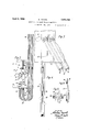
Figure 1 is a sectional, side elevation of a machine embodying features of the invention;
is a fragmentary, front elevation of the machine;
Figure 3 is a fragmentary, plan view showing particularly the blank forming dies and the magazines associated therewith;
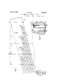
Figure 4 is a fragmentary elevation of one of the legs, broken away intermediate its ends for compactness of illustration, and shows the'manner in which the blanks are packaged in groups prior to their removal Figure 5 is a horizontal sectionthrough the discharge leg of a magazine, showing also a tie member applied to the blanks in the magazine;
Figure 6 is a view showing a stack or package of after removal from the machine;
Figure 7 is a horizontal, sectional view, largely diagrammatic, showing-how the'blank material is fed to the punches; and
Figure 8 is a fragmentary, transverse, sectional view showing particularly a detail of the cutting die.
, For purposes of illustration, the invention is shown as embodied in a machine for mak- 'velope, but which he blanks as they-are bound together plunger 12.
Serial 110,256,568.
ing and deliverin envelope fastening blanks of cross shape. ach of these blanks is provided with body members 1 adapted to have prongs formed therein and to be clinched to the back of an envelope by such prongs. Each blank also comprises fingers 2 which normally lie flat against the back of the enmay be bent outward into substantial parallel relation, inserted through i the sealing flap of the envelope, and then folded down again to substantially their original positions to secure the envelope closed. The blanks are formed of rather soft, flexible sheet metal.
It is desirable to form the blanks and then secure them in bundles or packages for shipment to envelope manufacturers. It is an important object of the present invention to avoid interruption of the blank forming operations or blanks when it becomes necessary to package and remove a group of the blanks from the machine. I
The blank forming machine comprises a frame 3 in which a main shaft 4 is journaled. The shaft & is continuously driven by apulley 5 or other suitable means and carries a crank pin 6 which, througha connecting rod 7, reciprocates a plunger head 8 common :to a plurality of plunger units. The plunger head 8 is provided with guide ribs 9 which slide in suitable guideways or grooves 10 formed in the frame 3.
As best seen in Figure 2, the plunger head 8 is provided with a plurality of T-shaped slots or guideways 11 with which the complementary shaped upper ends'of plungers 12 slidingly interfit. Each plunger 12 forms a part of a. punch unit 13 which is detachably secured upon a bed plate 1 1 of the frame 3 by means of bolts 15. Each unit comprises a die supporting plate 16, a die block 17 detachablyssecured thereto, and a body member 18 forming a guide for the reciprocable The body'18 may be detachably secured to the die supporting block 16 by bolts 19.
Each plunger 12 is cut away at the lower end thereof to form a cutting punch 20 of the configuration of one of the blanks. The
disarrangement of the formed punches are necessarily substantially separated from one another (see Figure 7) so that if the sheet of material 21 from which the blanks are to be punched were fed at right angles to the line of the punches, the proportion of waste of material would be very large. In order to avoid such waste, provision is made of guides 22 and 23 for guiding the material to the plungers in a path oblique to the line of the plungers, as shown in Figure 7. This method of feeding the material to the plungers causes the cuts made in the material by the plungers to be situated much more closely together than the plungers themselves are situated with respect to one another.
A magazine is provided for receiving the blanks punched by each of the punching units. This magazine is composed of two channeled bars 24 secured together in uni formly spaced relation by connecting mem bers 25. The magazine comprises a downwardly extending, introductory leg 26, an upwardly extending delivery leg 27, and a curved connecting portion 28 between said legs. As the blanks are punched, they descend in the introductory leg 26, then pass through the connecting portion 28, and up the delivery leg 27 so that they form an ascending column in leg 27. The blanks are guided in such movement by the channel bars 24 which embrace the fingers 2, 2 of the blanks.
It will be seen that the blanks rise in the delivery leg to a point substantially above the top of the introductory leg, so that the weight of the blanks in the delivery leg exceeds that of the blanks in the introductory leg. The excess weight of the blanks in the delivery leg tends to produce an unbalanced condition, and therefore to produce retrograde movement of the blanks in the magazine when the pressure of the plunger is withdrawn. This is overcome, however, by making the opening 29 in the upper face of the cutting die 17 somewhat smaller than the magazine, and flaring the opening downwardly, as indicated at 30. Each blank is stressed slightly by the cutting pressure, and consequently in its normal or unstressed condition is of slightly larger dimensions than the opening 29 through which it is punched. The blanks are therefore restrained by the die 17 against retrograde movement.
T e purpose in providing the magazine with g to enable the blanks to be removed in groups from the magazine without interrupting the operation of the punch and without interfering with the orderly reception of the blanks by the magazine. The magazine is provided with an index mark 31 and is also provided with suitable means, such as a second index mark 32, to indicate when a predetermined number of blanks stands above an upwardly extending delivery leg is the mark 31. The difference in level of the marks 31 and 32 may, for example, be equal to the thickness of a thousand blanks. When the attendant observes that the desired number of blanks to be formed into a package stands above the mark 31, he lifts the blanks situated above said mark without removing them from the magazine, as indicated in Figure 4, and inserts from beneath the stack of blanks thus lifted a staple-like binding number 33 which embraces the blank stack and has its legs situated at the vertices of diagonally opposite angles formed by the bodies 1 and fingers 2 of the blanks. When the lifted blanks have been thus united, the staple member 33 is withdrawn from the magazine, at the top, with the stack of blanks embraced by it, and thebundle or package illustrated in Figure 6 is completed by impaling holding and locking plates 34- and 35 upon the projecting ends of the staple legs. The stack binding means here disclosed is disclosed and claimed in my pending application Serial No. 241,001, filed December 19, 1927, entitled Blankstack and holder therefor.
It will be observed that the delivery legs of the several magazines lie side by side so that a single attendant can watch all of them and remove the blanks from them, as required.
lVhile I have illustrated and described in detail certain preferred forms of my invention, it is to be understood that changes may be made therein and the invention embodied in other structures. I do not, therefore, clesire to limit myself to the specific constructions illustrated, but intend to cover my invention broadly in whatever form its principle may be utilized.
I claim:
1. In combination, means for forming blanks, and a U-shaped magazine for re ceiving formed blanks, having a downwardly extending leg to receive the blanks, and a communicating, upwardly extending, straight leg from which the blanks may be removed, said upwardly extending leg being composed of separated confronting channel bars for embracing opposite extremities of the blanks to maintain the superposed blanks in substantially coinciding relation, said channel bars being spaced from one another sufficiently to permit a staple-like holding member to be inserted between them and beneath a stack formed of a multiplicity of blanks and then into embracing relation to such stack, so that the stack of blanks may be removed in orderly fashion and packaged with the holder.
2. In combination, means for forming blanks, and a U-shaped magazine for receiving formed blanks, having a downwardly extending leg to receive the blanks, and a communicating, upwardly extending, straight leg from which the blanks may be removed, said upwardly extending leg being composed of separated confronting channel bars for embracing opposite extremities of the blanks to maintain the superposed blanks in substantially coinciding relation, said channel bars being spaced from one another sufficiently to permit a staple-like holding member to be inserted between them and be ne'ath a stack formed of a multiplicity of blanks and then into embracing relation to such stack, so that the stack of blanksmay be removed in orderly fashion and packaged with the holder, the said channel bars being connected to one another only at one side, and there only at widely separated points.
3. In combination, means for forming blanks, and a U-shaped magazine for receiving formed blanks, having a downwardly extending leg to receive the blanks, and a communicating, upwardly extending, straight leg from which the blanks may be removed, said upwardly extending leg being composed of separated confronting channel bars for embracing opposite extremities of the blanks to maintain the superposed blanks in substantially coinciding relation, said channel bars beingspaced from one another sufficiently to permit a staple-like holding member to be inserted between them and beneath a stack formed of a multiplicity of blanks and then into embracing relation to such stack, so that the stack of blanks may be removed in orderly fashion and packaged with the holder, the said channel bars being connected to one another only at one side, and there only at widely separated points, and by members which are bowed outward to avoid interference with the blanks and with the staple-like holding member.
In testimony whereof I have afiixed my signature to this specification.
ABRAHAM NOVICK,
Priority Applications (1)
| Application Number | Priority Date | Filing Date | Title |
|---|---|---|---|
| US25656828 US1852722A (en) | 1928-02-24 | 1928-02-24 | Magazine for blank forming machinery |
Applications Claiming Priority (1)
| Application Number | Priority Date | Filing Date | Title |
|---|---|---|---|
| US25656828 US1852722A (en) | 1928-02-24 | 1928-02-24 | Magazine for blank forming machinery |
Publications (1)
| Publication Number | Publication Date |
|---|---|
| US1852722A true US1852722A (en) | 1932-04-05 |
Family
ID=22972726
Family Applications (1)
| Application Number | Title | Priority Date | Filing Date |
|---|---|---|---|
| US25656828 Expired - Lifetime US1852722A (en) | 1928-02-24 | 1928-02-24 | Magazine for blank forming machinery |
Country Status (1)
| Country | Link |
|---|---|
| US (1) | US1852722A (en) |
Cited By (3)
| Publication number | Priority date | Publication date | Assignee | Title |
|---|---|---|---|---|
| US2429821A (en) * | 1945-07-23 | 1947-10-28 | Motor Products Corp | Metal-working machine |
| US3149516A (en) * | 1960-04-22 | 1964-09-22 | Reynolds Metals Co | Machine with guide means for product |
| FR2340783A1 (en) * | 1976-02-14 | 1977-09-09 | Schuler Gmbh L | DEVICE INTENDED FOR ALIGNED STACKING OF PRESS CUT PARTS |
-
1928
- 1928-02-24 US US25656828 patent/US1852722A/en not_active Expired - Lifetime
Cited By (3)
| Publication number | Priority date | Publication date | Assignee | Title |
|---|---|---|---|---|
| US2429821A (en) * | 1945-07-23 | 1947-10-28 | Motor Products Corp | Metal-working machine |
| US3149516A (en) * | 1960-04-22 | 1964-09-22 | Reynolds Metals Co | Machine with guide means for product |
| FR2340783A1 (en) * | 1976-02-14 | 1977-09-09 | Schuler Gmbh L | DEVICE INTENDED FOR ALIGNED STACKING OF PRESS CUT PARTS |
Similar Documents
| Publication | Publication Date | Title |
|---|---|---|
| US1910688A (en) | Staple | |
| DE2927991A1 (en) | PACKAGING WITH CONTAINER PART | |
| US649762A (en) | Mechanism for punching metal strips. | |
| US1852722A (en) | Magazine for blank forming machinery | |
| CN105836234A (en) | Packing device of packaging paperboards | |
| US854706A (en) | Sheet-metal-punching press. | |
| US2697968A (en) | Machine for making set up boxes | |
| US4442742A (en) | Rotary apparatus for forming sheets with rounded corners | |
| US2299606A (en) | Method of making slide fasteners | |
| US2196440A (en) | Manufacture of cartons | |
| US1389197A (en) | Tray-making machine | |
| DE19820408C2 (en) | Device for punching out containers from a film web | |
| US1881868A (en) | Magazining device | |
| US1558345A (en) | Die | |
| US1778155A (en) | Punching and indexing apparatus for sheets, cards, and the like | |
| US1865947A (en) | Machine for forming perforated blanks | |
| US1847515A (en) | Machine for making blanks for cardboard boxes | |
| DE3701603A1 (en) | Flat-bed sheet-punching machine, especially for producing paper or cardboard blanks | |
| US1574481A (en) | Apparatus for and process of making pulley units | |
| US2014046A (en) | Box folding mechanism | |
| US1970550A (en) | Method and mechanism for assembling cartons | |
| US2136533A (en) | Machine for forming ribbed strips | |
| US2224993A (en) | Method of and apparatus for removing burrs from metallic fasteners | |
| US2867157A (en) | Machine for forming package trays | |
| US1474048A (en) | Method of and apparatus for cutting deckle-edged envelope blanks |