US1852700A - Visible link cartridge fuse - Google Patents
Visible link cartridge fuse Download PDFInfo
- Publication number
- US1852700A US1852700A US465747A US46574730A US1852700A US 1852700 A US1852700 A US 1852700A US 465747 A US465747 A US 465747A US 46574730 A US46574730 A US 46574730A US 1852700 A US1852700 A US 1852700A
- Authority
- US
- United States
- Prior art keywords
- fuse
- cartridge
- cartridge fuse
- visible link
- opening
- Prior art date
- Legal status (The legal status is an assumption and is not a legal conclusion. Google has not performed a legal analysis and makes no representation as to the accuracy of the status listed.)
- Expired - Lifetime
Links
- 238000007664 blowing Methods 0.000 description 5
- 230000000875 corresponding effect Effects 0.000 description 3
- 238000004880 explosion Methods 0.000 description 3
- 230000000694 effects Effects 0.000 description 2
- 239000002184 metal Substances 0.000 description 2
- 239000010445 mica Substances 0.000 description 2
- 229910052618 mica group Inorganic materials 0.000 description 2
- 238000005192 partition Methods 0.000 description 2
- 210000002105 tongue Anatomy 0.000 description 2
- 239000012780 transparent material Substances 0.000 description 2
- 238000005452 bending Methods 0.000 description 1
- 239000004020 conductor Substances 0.000 description 1
- 230000006378 damage Effects 0.000 description 1
- 238000001514 detection method Methods 0.000 description 1
- 239000000835 fiber Substances 0.000 description 1
- 239000000463 material Substances 0.000 description 1
- 239000011819 refractory material Substances 0.000 description 1
Images
Classifications
-
- H—ELECTRICITY
- H01—ELECTRIC ELEMENTS
- H01H—ELECTRIC SWITCHES; RELAYS; SELECTORS; EMERGENCY PROTECTIVE DEVICES
- H01H85/00—Protective devices in which the current flows through a part of fusible material and this current is interrupted by displacement of the fusible material when this current becomes excessive
- H01H85/02—Details
- H01H85/30—Means for indicating condition of fuse structurally associated with the fuse
Definitions
- the invention relates to improvements in cartridge fuses of the non-refillable type, particularly, and has for its principal object the provision of the ferrule, lug, and knife blade terminal type in which provision is made by which the location of the cartridge containing the blown fuse of a circuit may be readily ascertained, this information being obtained by providing a window in the cartridge at one end and forming the fuse memher with a reduced portion to localize the blowing of a fuse, and providing a reduced chamber in the cartridge to limit the effect of the blowing of the fuse and thereby eliminate danger in explosion incidental to the destruction of the fuse, and also localize the t explosion relatively to the window to more clearly indicate the blown fuse in the circuit.
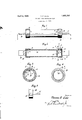
- Figure 1 is a side view partly broken away and in section of the improved fuse cartridge
- Figure 2 is a longitudinal sectional view on a plane indicated by the line 2-2 of Figure 1
- Figures 3 and 4 are transverse sectional views on planes indicated by the lines 33, and 44, respectively, of Figure 2, and
- Figure 5 is a view in elevation of one of the knife blade ferrules.
- the fuse cartridge includes a hollow tubular member 1 made of any suitable non-conducting material such as vulcanized fiber or its equivalent, said tubular body 1 having its r ends open, and provided with an opening 2 adjacent to one of the open ends thereof for the purpose to be hereinafter described.
- a cup-shaped metallic caps 3 and 4 Secured in any suitable manner on the ends of the body 1 are cup-shaped metallic caps 3 and 4, the cap 4 having an opening 5 correspond ing to the opening 2 and adapted to be arranged in alinement therewith to provide a window in the member, 6 designating a piece of mica or other suitable refractory and transparent material arranged between the flange of the cap 4 and the body 1 and closing the window formed by the openings 2 and 5.
- Caps 3 and 4 have openings 7 and 8, respectively, preferably formed by cutting the metal of the caps and bending the tongues 9 and 10 formed thereby inwardly, the outer portions of said tongues as shown at 11 and 12 being curved and providing a surface for engagement with the fuse element 13 that is passed longitudinally through the body portion 1 and has its ends 14 secured in any suitable manner to the outer surface of the caps, the curved portions 11 and 12 preventing breaking of the fuse element 13 and then to be secured to the outer portion of the caps.
- the fuse element 13 has its portion opposite the openings 2 and 5 reduced in width as shown at 15 to localize the blowing of the fuse occasioned by an overloading of the circuit in which the fuse is placed.
- the cartridge hereinbefore described is adapted for use in fuse boxes of the ferrule and knife blade type, and 18 and 19 indicate the ferrules in which are secured the blades 20 and 21, the ferrule 18 being provided with an opening 22 for alinementwith the openings 2 and 5 providing for detection through said openings of the condition of-"the fuse in the cartridge, as heretofore stated.
- a fuse cartridge a hollow body open at opposite ends, metal, cup-shaped caps closing the open ends of said body, a fuse element extending from end to end of said body and 95 terminally secured to said caps, a partition in said body intermediate of its ends and dividing the body into two chambers, the fuse element having a reduced portion located in one of said chambers, the body being provided 10 With an opening in its wall alined with the reduced portion of the fuse element, the cap on the corresponding end of the body having an opening alining with the opening in the body wall, and a plate of transparent material arranged between the body wall and cap and alined with said openings.
Landscapes
- Fuses (AREA)
Description
AprilS, 1932. T. F. COTE VISIBLE LINK CARTRIDGE FUSE Filed July 3, 1950 Patented Apr. 5, 1932 PATENT OFFICE THOMAS E. COTE, OF CLINTON, IOWA VISIBLE LINK CARTRIDGE FUSE Application filed July 3, 1930. Serial No. 465,747.
The invention relates to improvements in cartridge fuses of the non-refillable type, particularly, and has for its principal object the provision of the ferrule, lug, and knife blade terminal type in which provision is made by which the location of the cartridge containing the blown fuse of a circuit may be readily ascertained, this information being obtained by providing a window in the cartridge at one end and forming the fuse memher with a reduced portion to localize the blowing of a fuse, and providing a reduced chamber in the cartridge to limit the effect of the blowing of the fuse and thereby eliminate danger in explosion incidental to the destruction of the fuse, and also localize the t explosion relatively to the window to more clearly indicate the blown fuse in the circuit. K The invention will be described in detail hereinafter and will be found illustrated in the accompanying drawings, in which Figure 1 is a side view partly broken away and in section of the improved fuse cartridge, Figure 2 is a longitudinal sectional view on a plane indicated by the line 2-2 of Figure 1,
Figures 3 and 4 are transverse sectional views on planes indicated by the lines 33, and 44, respectively, of Figure 2, and
Figure 5 is a view in elevation of one of the knife blade ferrules.
In the drawings similar reference characters are used to designate corresponding parts throughout the several views.
The fuse cartridge includes a hollow tubular member 1 made of any suitable non-conducting material such as vulcanized fiber or its equivalent, said tubular body 1 having its r ends open, and provided with an opening 2 adjacent to one of the open ends thereof for the purpose to be hereinafter described. Secured in any suitable manner on the ends of the body 1 are cup-shaped metallic caps 3 and 4, the cap 4 having an opening 5 correspond ing to the opening 2 and adapted to be arranged in alinement therewith to provide a window in the member, 6 designating a piece of mica or other suitable refractory and transparent material arranged between the flange of the cap 4 and the body 1 and closing the window formed by the openings 2 and 5. Caps 3 and 4 have openings 7 and 8, respectively, preferably formed by cutting the metal of the caps and bending the tongues 9 and 10 formed thereby inwardly, the outer portions of said tongues as shown at 11 and 12 being curved and providing a surface for engagement with the fuse element 13 that is passed longitudinally through the body portion 1 and has its ends 14 secured in any suitable manner to the outer surface of the caps, the curved portions 11 and 12 preventing breaking of the fuse element 13 and then to be secured to the outer portion of the caps. The fuse element 13 has its portion opposite the openings 2 and 5 reduced in width as shown at 15 to localize the blowing of the fuse occasioned by an overloading of the circuit in which the fuse is placed.
16 indicates a partition of electrically nonconducting material closely fitting the bore of the tubular member 1 and arranged adjacent to the opening 2 so as to limit the efiect of the blowing of the fuse to a reduced compartment 17, thus adding to the safety of the fuse cartridge, by eliminating danger of explosion of the entire fuse, and also localizing the effect of the blowing of the fuse so that the cartridge containing the blown fuse may be readily detected by the smutting of the mica plate 6 when a fuse is blown.
The cartridge hereinbefore described is adapted for use in fuse boxes of the ferrule and knife blade type, and 18 and 19 indicate the ferrules in which are secured the blades 20 and 21, the ferrule 18 being provided with an opening 22 for alinementwith the openings 2 and 5 providing for detection through said openings of the condition of-"the fuse in the cartridge, as heretofore stated.
What is claimed is In a fuse cartridge, a hollow body open at opposite ends, metal, cup-shaped caps closing the open ends of said body, a fuse element extending from end to end of said body and 95 terminally secured to said caps, a partition in said body intermediate of its ends and dividing the body into two chambers, the fuse element having a reduced portion located in one of said chambers, the body being provided 10 With an opening in its wall alined with the reduced portion of the fuse element, the cap on the corresponding end of the body having an opening alining with the opening in the body wall, and a plate of transparent material arranged between the body wall and cap and alined with said openings.
In testimony whereof I afiix my signature.
THOMAS F. COTE.
Priority Applications (1)
| Application Number | Priority Date | Filing Date | Title |
|---|---|---|---|
| US465747A US1852700A (en) | 1930-07-03 | 1930-07-03 | Visible link cartridge fuse |
Applications Claiming Priority (1)
| Application Number | Priority Date | Filing Date | Title |
|---|---|---|---|
| US465747A US1852700A (en) | 1930-07-03 | 1930-07-03 | Visible link cartridge fuse |
Publications (1)
| Publication Number | Publication Date |
|---|---|
| US1852700A true US1852700A (en) | 1932-04-05 |
Family
ID=23849017
Family Applications (1)
| Application Number | Title | Priority Date | Filing Date |
|---|---|---|---|
| US465747A Expired - Lifetime US1852700A (en) | 1930-07-03 | 1930-07-03 | Visible link cartridge fuse |
Country Status (1)
| Country | Link |
|---|---|
| US (1) | US1852700A (en) |
Cited By (1)
| Publication number | Priority date | Publication date | Assignee | Title |
|---|---|---|---|---|
| US20050253679A1 (en) * | 2004-05-13 | 2005-11-17 | Chun-Chang Yen | Fuse structure with venting aperture |
-
1930
- 1930-07-03 US US465747A patent/US1852700A/en not_active Expired - Lifetime
Cited By (2)
| Publication number | Priority date | Publication date | Assignee | Title |
|---|---|---|---|---|
| US20050253679A1 (en) * | 2004-05-13 | 2005-11-17 | Chun-Chang Yen | Fuse structure with venting aperture |
| US6992560B2 (en) * | 2004-05-13 | 2006-01-31 | Chun-Chang Yen | Fuse structure |
Similar Documents
| Publication | Publication Date | Title |
|---|---|---|
| US1852700A (en) | Visible link cartridge fuse | |
| US821873A (en) | Electric fuse. | |
| US1562984A (en) | Incased fuse | |
| US1540119A (en) | Renewable fuse element | |
| US737281A (en) | Safety-fuse. | |
| US1861893A (en) | Firecracker | |
| US1446554A (en) | Fusible link | |
| US1334572A (en) | Renewable cartridge-fuse | |
| US2105113A (en) | Electric alarm switch | |
| US1447122A (en) | Fuse | |
| US1881351A (en) | Electric fuse and alpha method of assembling same | |
| US2668887A (en) | Mechanical indicating current limiter | |
| US1237211A (en) | Fuse. | |
| US1375171A (en) | Renewable saeety-etjse | |
| US1486960A (en) | Expulsion fuse box | |
| US1257100A (en) | Electrical fuse. | |
| US905905A (en) | Electric cut-out and holder. | |
| US1573392A (en) | Renewable fuse element | |
| US1074434A (en) | Fuse. | |
| US661241A (en) | Thermal cut-out or fuse. | |
| US1447150A (en) | Fuse | |
| US1565644A (en) | Automatic excess-heat fuse for electric machines and apparatus | |
| US1120221A (en) | Electric fuse. | |
| US1779697A (en) | Fuse indicator | |
| US945594A (en) | Fuse. |