US1852492A - Grate bar - Google Patents
Grate bar Download PDFInfo
- Publication number
- US1852492A US1852492A US329735A US32973529A US1852492A US 1852492 A US1852492 A US 1852492A US 329735 A US329735 A US 329735A US 32973529 A US32973529 A US 32973529A US 1852492 A US1852492 A US 1852492A
- Authority
- US
- United States
- Prior art keywords
- bars
- bar
- pipes
- grate
- pipe
- Prior art date
- Legal status (The legal status is an assumption and is not a legal conclusion. Google has not performed a legal analysis and makes no representation as to the accuracy of the status listed.)
- Expired - Lifetime
Links
- XLYOFNOQVPJJNP-UHFFFAOYSA-N water Substances O XLYOFNOQVPJJNP-UHFFFAOYSA-N 0.000 description 7
- 238000010276 construction Methods 0.000 description 4
- 238000001816 cooling Methods 0.000 description 4
- 230000008602 contraction Effects 0.000 description 2
- 239000002826 coolant Substances 0.000 description 2
- 230000000284 resting effect Effects 0.000 description 2
- 208000027418 Wounds and injury Diseases 0.000 description 1
- 238000005266 casting Methods 0.000 description 1
- 230000006378 damage Effects 0.000 description 1
- 230000000694 effects Effects 0.000 description 1
- 208000014674 injury Diseases 0.000 description 1
- 238000009434 installation Methods 0.000 description 1
- 238000004519 manufacturing process Methods 0.000 description 1
- 239000002184 metal Substances 0.000 description 1
- 239000002893 slag Substances 0.000 description 1
- 239000007787 solid Substances 0.000 description 1
Images
Classifications
-
- F—MECHANICAL ENGINEERING; LIGHTING; HEATING; WEAPONS; BLASTING
- F23—COMBUSTION APPARATUS; COMBUSTION PROCESSES
- F23H—GRATES; CLEANING OR RAKING GRATES
- F23H3/00—Grates with hollow bars
- F23H3/02—Grates with hollow bars internally cooled
Definitions
- This invention relates to grate bars for furnaces and particularly to demountable, water cooled grate bars; this being in the nature of an improvement on the bar described in an application for lletters Patent filed May 25, 1927 and bearing Serial Number l9-il,l08l
- the principal object of this invention is to provide grate bars that are adapted to be removebly supported on pipes through which water or other cooling medium may be circulated; the pipes being so arranged that they can be erected on the furnace plates or supports so as to serve as a base or foundation for the grate bars, but entirely independent thereof, and the bars are of such construction that they may be placed in or removed from the furnace withoutdisrupting; or disconnecting the pipe system.
- :inother object of the invention is to provide an arrangement of pipes for the cooling medium, permitting expansion, contraction and incidental movement of the bars and oipes together with the least number of connections, thus reducing to a minimum the liability of leakage as well as the cost of installation.
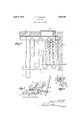
- ltn accomplishingthese and other objects of the invention, 1 have provided the improved details of construction, the preferred forms of which are illustrated in the accompan ring drawings, wherein lligure 1 is a horizontal sectional View of a portion of furnace equipped with grate bar. nd cooling pipes in accordance with the present invention. some of the grate bars being); removed for better illustration.
- Figure 2 is a perspective View of end portion: of: adjacent ,o rate bars illustrating the mounting and rocking i'neohanism therefor.
- Figure 3 is a cross section of one of the bars.
- FIG. 1 designates aside wall of a furnace fire hon supporting ends of the cross beams 2 and 3, which respectively, serve as front and rear supports for a section of grate bars and cooling pipes; the furnace door being designated at l.
- a pipe system composed of a plurality of U-shaped sections 5 joined end to end by preferably would be water, enters the pipe system at one end and flows back and forth through the coils, and passes out at the other end; the intake and outlet being through the front or side wall of the furnace as found convenient.
- the pipe coils may be limited to the length of a single bar or they may extend beyond the beam 2, as indiacted at 11, the
- Each bar 7 is an integral piece as shown in Figure 1, is formed on the under surface with a shallow groove 12 extending; the full length thereof for receiving a pipe 5 and which permits relative movement of the pipes and bars incident to expansion and contraction of these parts, or, if it is preferred. the grooves may be omitted and the bar rested flatly upon the pipe.
- the bars 7 are mounted pivotally or retatablv, on the pipes and are provided at opposite ends with downwardly extending arms 22 and 23 spaced apart and these are slotted to receive the kevs 25 which extend beneath the pipes to hold the parts in assembled relation.
- Each of the bars is also pro vided with a depending lever 26 for connection at their lower ends with a rod 27 which, in turn, connects with a lever 28, by means of which shaking of the grates may be effected.
- Many attempts have heretofore been made to keep the temperature of grate bars below the fusing point as a means of preventing the adhesion of slag and consequent clogging of the circulation vents and burninp: out of bars.
- a gratelconstruction comprising horizontal supports, apipe section resting thereon formed of aseriesof back and forth loops of regular spacing arranged in the same plane,
Landscapes
- Engineering & Computer Science (AREA)
- Chemical & Material Sciences (AREA)
- Combustion & Propulsion (AREA)
- Mechanical Engineering (AREA)
- General Engineering & Computer Science (AREA)
- Coke Industry (AREA)
Description
April 5, 1932. J. T. TAWLKS GRATE BAR INVENTOR 727mm /(5 Filed Jan. 2, 1929 A TTORNEYS Patented Apr. 5, 1932 STATES PATENT orrlce JUHN T. TAWLKS, OF EVERETT, WASHINGTON, ASSIGNOE TO TAWLKS GRATE BAR COM- PANY, A CORPORATION OF WASHINGTON ena'rn BAR Application filed January 2, 1929. ,Ser1a1 No. 329,735.
This invention relates to grate bars for furnaces and particularly to demountable, water cooled grate bars; this being in the nature of an improvement on the bar described in an application for lletters Patent filed May 25, 1927 and bearing Serial Number l9-il,l08l
The principal object of this invention is to provide grate bars that are adapted to be removebly supported on pipes through which water or other cooling medium may be circulated; the pipes being so arranged that they can be erected on the furnace plates or supports so as to serve as a base or foundation for the grate bars, but entirely independent thereof, and the bars are of such construction that they may be placed in or removed from the furnace withoutdisrupting; or disconnecting the pipe system.
:inother object of the invention is to provide an arrangement of pipes for the cooling medium, permitting expansion, contraction and incidental movement of the bars and oipes together with the least number of connections, thus reducing to a minimum the liability of leakage as well as the cost of installation.
Uther objects of the invention reside in the various details of construction and in the combination oi parts as is hereinafter described.
ltn accomplishingthese and other objects of the invention, 1 have provided the improved details of construction, the preferred forms of which are illustrated in the accompan ring drawings, wherein lligure 1 is a horizontal sectional View of a portion of furnace equipped with grate bar. nd cooling pipes in accordance with the present invention. some of the grate bars being); removed for better illustration.
Figure 2 is a perspective View of end portion: of: adjacent ,o rate bars illustrating the mounting and rocking i'neohanism therefor.
Figure 3 is a cross section of one of the bars.
deferring more in detail to the drawings- 1 designates aside wall of a furnace fire hon supporting ends of the cross beams 2 and 3, which respectively, serve as front and rear supports for a section of grate bars and cooling pipes; the furnace door being designated at l. Disposed on the beams 2 and 3, which are substantially in the same horizontal plane, is a pipe system composed of a plurality of U-shaped sections 5 joined end to end by preferably would be water, enters the pipe system at one end and flows back and forth through the coils, and passes out at the other end; the intake and outlet being through the front or side wall of the furnace as found convenient. The pipe coils may be limited to the length of a single bar or they may extend beyond the beam 2, as indiacted at 11, the
full length of two or more sections of bars placed end to end.
Each bar 7 is an integral piece as shown in Figure 1, is formed on the under surface with a shallow groove 12 extending; the full length thereof for receiving a pipe 5 and which permits relative movement of the pipes and bars incident to expansion and contraction of these parts, or, if it is preferred. the grooves may be omitted and the bar rested flatly upon the pipe.
The bars 7 are mounted pivotally or retatablv, on the pipes and are provided at opposite ends with downwardly extending arms 22 and 23 spaced apart and these are slotted to receive the kevs 25 which extend beneath the pipes to hold the parts in assembled relation. Each of the bars is also pro vided with a depending lever 26 for connection at their lower ends with a rod 27 which, in turn, connects with a lever 28, by means of which shaking of the grates may be effected. Many attempts have heretofore been made to keep the temperature of grate bars below the fusing point as a means of preventing the adhesion of slag and consequent clogging of the circulation vents and burninp: out of bars. but as a general thing, owing to the intense furnace heat and the different rates of expansion between the super-heated bars and the water cooled pipes, such water IOU cooling systems have broken down through leakage. The system herein described overcomes the liability of leakage, has withstood the severest service tests and by reason of the fact that the piping is in intimate contact with the grate bars and all lie in the same plane with sleeve joints only, is subject to no twisting or pulling strains. The piping arrangement offers the minimum of resistance to the water flow, thus facilitating drainage and reducing the amount of water 7 required. In case of any stoppage of the cooling system, the bar being of the conventional type, will function in the usual manner and without injury to the piping until the stoppage can be remedied.
Another advantage of the above described construction resides in the fact that the coils resting directly on the supports 2and 3, will tend to reduce the disintegrating effect of' the heat thereon, thus tending to keep the surface level and the bars in better alinement- One of the greatest advantages over other types of bars is that this bar can be punched put of ordinary boiler plate metal; the webs being formed as shown in Figure 2, thus Y avoiding the use of patterns, molds and castings, and making the manufacture of the grate bars posslble 1n machlne shops lnstead of foundrles as heretofore.
It is further apparent that by arranging the legs of the pipe sections in parallel relation and all equally spaced, this will permit interchangeable use of one piece grate bars which are easily and quickly replaceable thereon.
Having thus described my invention, what I claim as new therein and desire to secure by Letters Patent, is:
A gratelconstruction comprising horizontal supports, apipe section resting thereon formed of aseriesof back and forth loops of regular spacing arranged in the same plane,
a series of grate bars supported rotatably thereon and having solid portions directly overlying the pipes as a protection thereto,
each having U-shaped and slotted rocking arms extending downwardly to embrace the pipe on which it is supported, a key inserted through the arm slots to hold bar and pipe .in contacted relation, rods connecting therocking arms and means for oscillating the same.
Signed at Everett, Washington, this 23rd day of November, 1928.
JOHN T. TAWLKS.
Priority Applications (1)
| Application Number | Priority Date | Filing Date | Title |
|---|---|---|---|
| US329735A US1852492A (en) | 1929-01-02 | 1929-01-02 | Grate bar |
Applications Claiming Priority (1)
| Application Number | Priority Date | Filing Date | Title |
|---|---|---|---|
| US329735A US1852492A (en) | 1929-01-02 | 1929-01-02 | Grate bar |
Publications (1)
| Publication Number | Publication Date |
|---|---|
| US1852492A true US1852492A (en) | 1932-04-05 |
Family
ID=23286771
Family Applications (1)
| Application Number | Title | Priority Date | Filing Date |
|---|---|---|---|
| US329735A Expired - Lifetime US1852492A (en) | 1929-01-02 | 1929-01-02 | Grate bar |
Country Status (1)
| Country | Link |
|---|---|
| US (1) | US1852492A (en) |
Cited By (4)
| Publication number | Priority date | Publication date | Assignee | Title |
|---|---|---|---|---|
| US2608958A (en) * | 1949-08-20 | 1952-09-02 | Charles M Hazelton | Grate bar |
| US3439652A (en) * | 1967-08-07 | 1969-04-22 | Joseph A Clark | Furnace grate construction |
| US4026247A (en) * | 1975-12-15 | 1977-05-31 | S. J. Agnew | Fluid cooled dump grate |
| WO2009023977A3 (en) * | 2007-08-22 | 2009-06-18 | Doikos Investments Ltd | Liquid-cooled grill plate comprising wear plates and stepped grill made of such grill plates |
-
1929
- 1929-01-02 US US329735A patent/US1852492A/en not_active Expired - Lifetime
Cited By (8)
| Publication number | Priority date | Publication date | Assignee | Title |
|---|---|---|---|---|
| US2608958A (en) * | 1949-08-20 | 1952-09-02 | Charles M Hazelton | Grate bar |
| US3439652A (en) * | 1967-08-07 | 1969-04-22 | Joseph A Clark | Furnace grate construction |
| US4026247A (en) * | 1975-12-15 | 1977-05-31 | S. J. Agnew | Fluid cooled dump grate |
| WO2009023977A3 (en) * | 2007-08-22 | 2009-06-18 | Doikos Investments Ltd | Liquid-cooled grill plate comprising wear plates and stepped grill made of such grill plates |
| US20110232623A1 (en) * | 2007-08-22 | 2011-09-29 | Doikos Investments Limited | Liquid-cooled grill plate comprising wear plates and stepped grill made of such grill plates |
| EA016515B1 (en) * | 2007-08-22 | 2012-05-30 | Доикос Инвестмент Лимитед | Liquid-cooled grill plate comprising wear plates and stepped grill made of such grill plates |
| CN101960220B (en) * | 2007-08-22 | 2012-10-10 | 多伊克斯投资有限公司 | Fluid-cooled baking pan with wear-resistant plates and a stepped grill consisting of such a baking pan |
| US8590465B2 (en) | 2007-08-22 | 2013-11-26 | Doikos Investments Ltd. | Liquid-cooled grill plate comprising wear plates and stepped grill made of such grill plates |
Similar Documents
| Publication | Publication Date | Title |
|---|---|---|
| US3007455A (en) | Vapor generator wall and buckstay arrangement | |
| US1852492A (en) | Grate bar | |
| US2305611A (en) | Heater | |
| US2415068A (en) | Tube spacer and support | |
| US908236A (en) | Burner. | |
| US1666028A (en) | Fluid heating | |
| US547802A (en) | Grate | |
| US184948A (en) | Improvement in sediment-collectors for steam-boilers | |
| US1633975A (en) | Superheater baffle | |
| US1977637A (en) | Boiler superheater support | |
| US1674080A (en) | Furnace baffle | |
| US2630790A (en) | Steam generator | |
| US2211270A (en) | Grate | |
| US1926046A (en) | Water tube boiler baffle | |
| US2726644A (en) | Heating boiler with horizontal circulation produced by upflow pipes | |
| US2294946A (en) | Skewback | |
| US1021597A (en) | Device for steam-boilers. | |
| US1663910A (en) | Water-tube boiler | |
| US1147216A (en) | Steam-boiler furnace. | |
| US1764173A (en) | Furnace wall | |
| US1990945A (en) | Boiler and superheater | |
| KR200169989Y1 (en) | Structure of a screen tube | |
| US554872A (en) | hersey | |
| US2074900A (en) | Boiler | |
| KR890006774Y1 (en) | Device for exhausting of hot-water boiler |