US1852449A - Window display support - Google Patents
Window display support Download PDFInfo
- Publication number
- US1852449A US1852449A US457968A US45796830A US1852449A US 1852449 A US1852449 A US 1852449A US 457968 A US457968 A US 457968A US 45796830 A US45796830 A US 45796830A US 1852449 A US1852449 A US 1852449A
- Authority
- US
- United States
- Prior art keywords
- cup
- display support
- display
- attached
- hole
- Prior art date
- Legal status (The legal status is an assumption and is not a legal conclusion. Google has not performed a legal analysis and makes no representation as to the accuracy of the status listed.)
- Expired - Lifetime
Links
- 239000011521 glass Substances 0.000 description 7
- 229920001971 elastomer Polymers 0.000 description 5
- 238000010276 construction Methods 0.000 description 2
- 230000004048 modification Effects 0.000 description 2
- 238000012986 modification Methods 0.000 description 2
- 229920001342 Bakelite® Polymers 0.000 description 1
- 101100327917 Caenorhabditis elegans chup-1 gene Proteins 0.000 description 1
- 101100001672 Emericella variicolor andG gene Proteins 0.000 description 1
- 239000004637 bakelite Substances 0.000 description 1
- 239000000835 fiber Substances 0.000 description 1
- 230000005484 gravity Effects 0.000 description 1
- 239000000463 material Substances 0.000 description 1
- 230000008520 organization Effects 0.000 description 1
- 239000002023 wood Substances 0.000 description 1
Images
Classifications
-
- G—PHYSICS
- G09—EDUCATION; CRYPTOGRAPHY; DISPLAY; ADVERTISING; SEALS
- G09F—DISPLAYING; ADVERTISING; SIGNS; LABELS OR NAME-PLATES; SEALS
- G09F1/00—Cardboard or like show-cards of foldable or flexible material
- G09F1/10—Supports or holders for show-cards
Definitions
- This invention relates to devices for holding flags, ornaments or advertising matter inside show windows in stores or oflice windows in ofiice buildings or ordinary windows in dwelling houses.
- the device also preferably includes means by which a card on which is a photograph, picture or other ornament can be held in position with reference to such flags inside the window.
- the device is of such character that it can instantly be attached or detached but will be held in place so firmly that it can support a go very substantial weight.
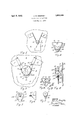
- Fig. 1 is an elevation of the device with display articles in position as viewed from the front through a pane of glass.
- Fig. 2 is a front elevation of the body with the suction cup removed and with a nail in place.
- Fig. 3 is a front elevation Similar to Fig. 1, but on an enlarged scale and showing mainly the support itself.
- Fig. 3A is a front elevation similar to Fig. 2 of a modification of the holding body, part being broken away to show the interior.
- Fig. 3B is a side elevation of another form of nail or means by which to hang a display article.
- Fig. 4.- is a side elevation partly in suction as from the left of Fig. 3, but with the flags removed and other display articles attached in a different way, the body being shown partly in section to show the construction.
- Fig. 5 is a front elevation of a modified form of support the suction cup being broken away and part being shown in section to show the construction.
- Fig. 6 is a side elevation of the suction cup shown in Fig. 5 removed from the body.
- Fig. 7 is a front elevation similar to Fig. 5 of another modification.
- A represents a sheet of 1930.
- B is the body of my holding device Shown as made of a block of wood bakelite, fibre or other suitable material of substantially triangular shape with the top side 12 substantially horizontal when in positionand having the holes 10 and 11 which are relatively vertical if viewed from theside as in Fig. 4 or as making an angle if viewed as shownin Fig. 3.
- holes 10 and 11 are eachadapted to receive a staff such as 20 or 21 each of which may be part of a flag suchas F or G or a banner, fan or other similar article.
- the sides 13 and 14 converge to arounded "o5 point 15 and in the front near the bottom is a nail hole 18 adapted to receivea nail such as K by which a card or similar article such as H can be attached or detached.
- R isa brace'attached to the front of the body proximate and under cup C in such a position that whenthe cup is in holding position against the glass it touches along the lower part of the cup thereby stiffening that part and helping to keep the center of gravity of the whole outfit, including the card H and the flags F andG by their weight, from forcing out the top part such as 9 of cup G, thus allowing the air to enter.
- Brace R is preferably of curved shape where it touches cup C.
- the hole 18 is one means by which to hang a display article such as H, but I prefer to use also another hole or horizontal groove 19 which makes, a sort of hook 29 whereby a loop such as 28 attached to an article such as 90 M can be used to support such an article M, as shown in Fig. 4.
- FIG. 5 I show a body 50 of a different shape having in the top one stafi' hole 51 and having at the lower front 54: no nail hole.
- the brace 40 is straight instead of curved or annular as shown at R and in the front at the bottom, the means to hang or display is only the nail hole 18, there being no hook such as 29 nor groove such as 19.
- the suction cup such as C
- the suction cup may be attached by means of a bolt 24 and nut 25 as shown in Fig. i or as shown in Figs. 5 and 6, the rubber part 52 may be integral with a screw 55 which is screwed into a suitable hole'56 in body 50.
- Fig. 3A I show a triangular body having a brace 62 and hole to receive an at-' taching shank 61 for a suction cup and inthe top, the. diverging holes 63 and 64 which are wider at the top than at the bottom so that a staff can be easily put in-or taken out.
- a nail 65 having an elongated head with an annular groove in ,which'a loop such as 28 can be held and a pointed shank 66 to enter a nail hole such as 18.
- a body of substantially triangular shape having a flat front and in the top qrelatively vertical diverging holes each adapted to receive a staff and in the front,
- a window display support the combination of a body having a flat front and in the top a relatively vertical hole adapted to receive a staff and in the front near the bottom means by which to hang a display article; with a concavo-convex rubber suction cup having a flat back whichis fastened to, the flat front of the body and adapted to adhere to a pane of glass; and a brace attached to the front of the body and which fits and extends under the convex part of said cup.
- a window display support the combination of a body having a flat front andin the top a hole adapted to receive a stafi with a concavo-convex rubber suction cup having a flat back which is fastened to the flat front of the body and adapted to adhere to apane of glass; and a brace attached to the front of the body and which fits and extends under the convex part of said cup.
Landscapes
- Physics & Mathematics (AREA)
- General Physics & Mathematics (AREA)
- Engineering & Computer Science (AREA)
- Theoretical Computer Science (AREA)
- Hooks, Suction Cups, And Attachment By Adhesive Means (AREA)
Description
A ril 5, 1932. J, w, DEMPSEY' 1,852,449
WINDOW DI SPLAY SUPPORT Filed May 51, 1950 IN ENTOR ATTORNEY Patented Apr. 5, 1932 UNITED STATES JOHN W. DEMPSEY, OF
LOWELL, MASSACHUSETTS wnvnow DISPLAY SUPPORT Application filed May 31,
This invention relates to devices for holding flags, ornaments or advertising matter inside show windows in stores or oflice windows in ofiice buildings or ordinary windows in dwelling houses.
While it might be used outside, its special purpose is to provide the occupant with a neat, convenient holder by which flags, fans or other similar devices which include a staff can be supported on the inside of a window pane in any position desired.
The device also preferably includes means by which a card on which is a photograph, picture or other ornament can be held in position with reference to such flags inside the window.
The device is of such character that it can instantly be attached or detached but will be held in place so firmly that it can support a go very substantial weight.
In the drawings, Fig. 1 is an elevation of the device with display articles in position as viewed from the front through a pane of glass.
Fig. 2 is a front elevation of the body with the suction cup removed and with a nail in place.
Fig. 3 is a front elevation Similar to Fig. 1, but on an enlarged scale and showing mainly the support itself.
Fig. 3A is a front elevation similar to Fig. 2 of a modification of the holding body, part being broken away to show the interior.
Fig. 3B is a side elevation of another form of nail or means by which to hang a display article.
Fig. 4.- is a side elevation partly in suction as from the left of Fig. 3, but with the flags removed and other display articles attached in a different way, the body being shown partly in section to show the construction.
Fig. 5 is a front elevation of a modified form of support the suction cup being broken away and part being shown in section to show the construction.
Fig. 6 is a side elevation of the suction cup shown in Fig. 5 removed from the body.
Fig. 7 is a front elevation similar to Fig. 5 of another modification.
In the drawings, A represents a sheet of 1930. Serial No. 457,968.
glass which may be a store or oflice window or an ordinary window pane in a dwelling house.
B is the body of my holding device Shown as made of a block of wood bakelite, fibre or other suitable material of substantially triangular shape with the top side 12 substantially horizontal when in positionand having the holes 10 and 11 which are relatively vertical if viewed from theside as in Fig. 4 or as making an angle if viewed as shownin Fig. 3.
These holes 10 and 11 are eachadapted to receive a staff such as 20 or 21 each of which may be part of a flag suchas F or G or a banner, fan or other similar article. v
The sides 13 and 14 converge to arounded "o5 point 15 and in the front near the bottom is a nail hole 18 adapted to receivea nail such as K by which a card or similar article such as H can be attached or detached.
Cis a concavo-convex rubber suction cup 7 which is fixed to body B and'is adapted to adhere to a pane of glass such as A when pressed against it and then allowed to expand.
R isa brace'attached to the front of the body proximate and under cup C in such a position that whenthe cup is in holding position against the glass it touches along the lower part of the cup thereby stiffening that part and helping to keep the center of gravity of the whole outfit, including the card H and the flags F andG by their weight, from forcing out the top part such as 9 of cup G, thus allowing the air to enter.
Brace R is preferably of curved shape where it touches cup C.
The hole 18 is one means by which to hang a display article such as H, but I prefer to use also another hole or horizontal groove 19 which makes, a sort of hook 29 whereby a loop such as 28 attached to an article such as 90 M can be used to support such an article M, as shown in Fig. 4.
When the air begins to enter the cup C, it lets go its grip and the whole organization falls.
In Fig. 5, I show a body 50 of a different shape having in the top one stafi' hole 51 and having at the lower front 54: no nail hole.
There is a concavo-convex cup 52, however, similar to C and proximate and under the cup 1 is a brace 53 attached to the front of body 50.
In Fig. 7 the brace 40 is straight instead of curved or annular as shown at R and in the front at the bottom, the means to hang or display is only the nail hole 18, there being no hook such as 29 nor groove such as 19.
The suction cup, such as C, may be attached by means of a bolt 24 and nut 25 as shown in Fig. i or as shown in Figs. 5 and 6, the rubber part 52 may be integral with a screw 55 which is screwed into a suitable hole'56 in body 50.
In Fig. 3A, I show a triangular body having a brace 62 and hole to receive an at-' taching shank 61 for a suction cup and inthe top, the. diverging holes 63 and 64 which are wider at the top than at the bottom so that a staff can be easily put in-or taken out.
a The means by which to hang a display article near the bottom is a nail 65 having an elongated head with an annular groove in ,which'a loop such as 28 can be held and a pointed shank 66 to enter a nail hole such as 18. V
I claim:
i 1. In a w ndow display support, the combination ofa body of substantially triangular shape having a flat front and in the top qrelatively vertical diverging holes each adapted to receive a staff and in the front,
near the bottom, means by which to hang a display. article; with a concavo-convex rubber suction cup having a fiat back which is fixed to the flat front of the body and adapted to adhere toa pane of glass; and a brace attached to the front of thebody and which fits and extends under the convex part of said cup.
2. Ina window display support, the combination of a body having a flat front and in the top a relatively vertical hole adapted to receive a staff and in the front near the bottom means by which to hang a display article; with a concavo-convex rubber suction cup having a flat back whichis fastened to, the flat front of the body and adapted to adhere to a pane of glass; and a brace attached to the front of the body and which fits and extends under the convex part of said cup.
3. In a window display support, the combination of a body having a flat front andin the top a hole adapted to receive a stafi with a concavo-convex rubber suction cup having a flat back which is fastened to the flat front of the body and adapted to adhere to apane of glass; and a brace attached to the front of the body and which fits and extends under the convex part of said cup.
JOHN W. DEMP's Y.
Priority Applications (1)
| Application Number | Priority Date | Filing Date | Title |
|---|---|---|---|
| US457968A US1852449A (en) | 1930-05-31 | 1930-05-31 | Window display support |
Applications Claiming Priority (1)
| Application Number | Priority Date | Filing Date | Title |
|---|---|---|---|
| US457968A US1852449A (en) | 1930-05-31 | 1930-05-31 | Window display support |
Publications (1)
| Publication Number | Publication Date |
|---|---|
| US1852449A true US1852449A (en) | 1932-04-05 |
Family
ID=23818803
Family Applications (1)
| Application Number | Title | Priority Date | Filing Date |
|---|---|---|---|
| US457968A Expired - Lifetime US1852449A (en) | 1930-05-31 | 1930-05-31 | Window display support |
Country Status (1)
| Country | Link |
|---|---|
| US (1) | US1852449A (en) |
Cited By (1)
| Publication number | Priority date | Publication date | Assignee | Title |
|---|---|---|---|---|
| US3152832A (en) * | 1963-10-14 | 1964-10-13 | Emil W Kamp | Weather shield for automobile windshields |
-
1930
- 1930-05-31 US US457968A patent/US1852449A/en not_active Expired - Lifetime
Cited By (1)
| Publication number | Priority date | Publication date | Assignee | Title |
|---|---|---|---|---|
| US3152832A (en) * | 1963-10-14 | 1964-10-13 | Emil W Kamp | Weather shield for automobile windshields |
Similar Documents
| Publication | Publication Date | Title |
|---|---|---|
| US1681586A (en) | Display-card holder | |
| US1448664A (en) | Display device | |
| US1970370A (en) | Floral device or garland | |
| US3969837A (en) | Display figure | |
| US1914951A (en) | Suspending device | |
| US6193396B1 (en) | Hanging holder for decorations | |
| US1852449A (en) | Window display support | |
| US1924074A (en) | Support for curtains and other light articles | |
| US2524647A (en) | Ornamental slip fit picture support unit | |
| US3279736A (en) | Support for display form | |
| US9517655B2 (en) | Display frame | |
| US484335A (en) | Suspension-hook | |
| US1873506A (en) | Window shade and curtain fixture | |
| US1147863A (en) | Suspending device. | |
| US424239A (en) | Wardrobe-hook | |
| US1371079A (en) | Display device | |
| US2125488A (en) | Sign | |
| US1820157A (en) | Transparent flag | |
| US2412834A (en) | Hamper or bag support | |
| US2406743A (en) | Reflected price tag or the like | |
| US2446832A (en) | Pendent dress form | |
| US977395A (en) | Display device. | |
| US1801387A (en) | Protective hanger and holder for emblems | |
| US2576705A (en) | Device for hanging floral displays | |
| US1210034A (en) | Hanger for pictures. |