US1852425A - Radiator hood - Google Patents
Radiator hood Download PDFInfo
- Publication number
- US1852425A US1852425A US479259A US47925930A US1852425A US 1852425 A US1852425 A US 1852425A US 479259 A US479259 A US 479259A US 47925930 A US47925930 A US 47925930A US 1852425 A US1852425 A US 1852425A
- Authority
- US
- United States
- Prior art keywords
- radiator
- rods
- hood
- plates
- plate
- Prior art date
- Legal status (The legal status is an assumption and is not a legal conclusion. Google has not performed a legal analysis and makes no representation as to the accuracy of the status listed.)
- Expired - Lifetime
Links
- 230000008878 coupling Effects 0.000 description 20
- 238000010168 coupling process Methods 0.000 description 20
- 238000005859 coupling reaction Methods 0.000 description 20
- 238000010276 construction Methods 0.000 description 5
- XLYOFNOQVPJJNP-UHFFFAOYSA-N water Substances O XLYOFNOQVPJJNP-UHFFFAOYSA-N 0.000 description 5
- 238000006073 displacement reaction Methods 0.000 description 3
- 230000004048 modification Effects 0.000 description 2
- 238000012986 modification Methods 0.000 description 2
- XUKUURHRXDUEBC-KAYWLYCHSA-N Atorvastatin Chemical compound C=1C=CC=CC=1C1=C(C=2C=CC(F)=CC=2)N(CC[C@@H](O)C[C@@H](O)CC(O)=O)C(C(C)C)=C1C(=O)NC1=CC=CC=C1 XUKUURHRXDUEBC-KAYWLYCHSA-N 0.000 description 1
- 241000733322 Platea Species 0.000 description 1
- 239000003086 colorant Substances 0.000 description 1
- 230000000694 effects Effects 0.000 description 1
- 238000004519 manufacturing process Methods 0.000 description 1
- 239000004579 marble Substances 0.000 description 1
- 239000000463 material Substances 0.000 description 1
- 239000002184 metal Substances 0.000 description 1
- 239000002023 wood Substances 0.000 description 1
Images
Classifications
-
- F—MECHANICAL ENGINEERING; LIGHTING; HEATING; WEAPONS; BLASTING
- F24—HEATING; RANGES; VENTILATING
- F24D—DOMESTIC- OR SPACE-HEATING SYSTEMS, e.g. CENTRAL HEATING SYSTEMS; DOMESTIC HOT-WATER SUPPLY SYSTEMS; ELEMENTS OR COMPONENTS THEREFOR
- F24D19/00—Details
- F24D19/06—Casings, cover lids or ornamental panels, for radiators
- F24D19/061—Radiator shelves
Definitions
- This invention relates to hoods for use in connection with radiators of various kinds and classes, i'or the purpose of dellecting the heatrising therefrom and 'further lo form a shelf or support upon which various arlil ticles may be placed; and the object of the invention is to provide a device of the class speciied, the hood of which consists of tele scoping parts whereby the same may be mounted upon radiators of dii'ierent length, the width olf said telescoping parts being such as to adapt the same for use on substantially any size and style oi radiator, which is in conventional use; a further object being to provide a simple and yet strong and durable means for coupling the hood with the radiator in such manner that the hood can safely support any articles placed thereon and also to provide a space between the top or' the radiator coils and the top of said hood; a further object being to arrange within the space formed in the hood, a pan in which water may be placed lo maintain as near as possible, a moist rather than dry
- the invention consists in a device of the class and ior the purpose specified which is simple in construction, eiiicient in use, and which is constructed as hereinafter described and claimed.
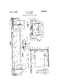
- rIhe invention described and claimed herein is a division oi a prior application namelyd by me November 25, 1929, Serial Number i09,500, and is fully disclosed in the following specification, of which the accompany ing drawings form a part, in which theA separate parts of my improvementare designated by suitable reference characters in each oi the views, and in which Fig. 1 is a longitudinal sectional view through my improved hood illustrating the manner of coupling the same with the end coils oi a radiator.
- Fig. 2 is a partial section on the line 2-2 of Fig. l.
- Fig. 3 is a section on the 1;
- Fig. l is a sectional detail view showing a modilication.
- FIG. 5 represents the coils of a radiator of any kind or class, the upper ends' of the separate coils being placed in communication by couplings 6 which bridge said coils.
- I provide a hood consisting of two parts 7 and 8 which are U- shaped in cross-sectional form, the part 8 being arranged outwardly of the part 7 and the latte-r part telescoping with the part 8 so that the end wall 9 of the part 7 may be moved relatively to the end wall 10 ol the part 8.
- the side wall 11 of the part 8 has a downwardly extending and angularly disposed deflector 12 terminating in an inwardly and upwardly arranged flange 13.
- the corresponding wall 14 of the part 7 is also provided with a deliector 15, the lower end of which rests in and is guided by the flange 18 and the telescoping movement of the parts.
- the other side wall 16 of the part 8 terminates in an inwardly and upwardly di rected flange 17 in whichv the lower edge of part 7 operates, thus retaining the parts 7 and 8 against displacement in their telescoping movement.
- the end wall 9 of the part 7 has an extension 9a folded inwardly upon the inner face of said wall, which extension terminates below the top wall of the part 7 in an inwardly directed flange 9b which forms a lock member to retain the part against displacement as later described.
- the end wall 10 is of similar construction and has the extension 10g terminating in the llange or lock member 10 .f Y
- the plate 19 is provided at its outer end with an upwardly extending flange 20 which is normally arranged adjacent the end walls 9 and 10 oi the hood ⁇ when mounted in position as clearly seen in Figs. 1 and 2 of the drawings. This plate is adapted to rest line 3-3 of Fig.
- I provide a transverse bar 22,V the ends of which have threaded holes tov receive coupling rods 23 or the threaded end portions 24 thereof, the upper ends of said rods having elongated loop-shaped heads 25 by means of which the rods may be ⁇ rotated in adjustably clamping the plates 19 in position.
- the rods 23 will be coupled with each end of the bar 22 and when so coupled, the entire unit ⁇ will be placed between two of the coils of the radiator beneath the bridge couplings G and sof as to extend the heads 25 above the coils, after which the plates 19 are mounted in position by passing the headsl 25 of the rods 23 through the elongated apertures 21 and then rotating said rods to draw the bar or bars 22 upwardly and the plates 19 downwardly.
- the plates 19 are clamped ifi-'position in suoli manner as to arrange the flanges 2O outwardly with respect to the outer faces of the end coils of the radiator, and when secured in position an elongated water pan 26 is placed upon the plates 19 and arranged between the Yheads 25 of the rods 23 and preferably of such length as to extend to a point adjacent each of the flanges 20 in the manner seen in Fig. 1 Yof the drawings; and the hood may now be placed in position.
- the parts 7 and 8 are separated to a suicient degree to permit the free placement of the'part 8 upon the adjacent plate 19:, it being understood that the flange 10b is passed beneath said plateas clearly seen in Fig. 1, so as to lock the part 8 against displacement from the radiator, aft-er which 7 is' moved inwardly to bring the flange 9b thereof beneath the plate 19 at the other end of the radiator, the party 8 being held against movement in this operation.
- the top wall of the part 8 is providedadjacent the end wall 10 with an aperture in which is mounted a cup-shaped filling cup and gage device 27 which extends well within the pan 26.
- This cup facilitates the filling of the pan and alsoV serves las a gage to @i indicate the level of water therein.v
- the water in the pan may be maintained at a proper level at all times without removing the hood from the radiator.
- the in* ner end of the top wall of the part 7 Y has van elongated .aperture 28 sufficiently largeto clear the cap 27. It is also preferred that clearance be provided between the fiange 10b and the adjacent side walls 11 and 16 as seen at 29, note Figs. 2 and 3, to permit the side walls 14 and 18 to move to a point adjacent the end wall 10 of the part 8.
- a mounting plate 19a is mounted upon and coupled with the coils 5a of aradiator by coupling rods 23a similar to the rods 23, the plate having an upwardly extending flange 20a which differs from the flange 2Ov in that it has a horizon tally and lateral-'ly extending part 20?) having one or more.
- threaded holes 20c to receive machine screws 30y for securing the slab 31V to the mounting plate 19a and to arrange the same above and in spaced relation to the topof the coils 5a.
- the slab 31 may be composed of any suitable material such for example as wood, marble, metal or the like. l/Vhile this slab forms a hood and shelf member, it does not necessarily include side wall members.
- yoke-shaped spacing member 26d' preferably arranged centrally of the hood and which serves to supportthe top walls 7 and 8 of the hood in spaced relation with the upper edge of the pan 26, especially when comparatively heavy articles are mounted upon the hood, and it will be understood that two or more of these devices may be employed if desired.
- hood may be painted or otherwise treatedto produce the same in any desired colors o-r color effects to render the device neat and ornamental in appearance as well as being practical in use.
- a mounting and supporting device for radiator hoods of the class described comprising mounting plates disposed upon the end coils of a radiator and projecting beyond the ends ot' the radiator, said plates having spaced elongated apertures, means for coupling the plates to the radiators comprising au elongated coupling bar, coupling rods in screw threaded engagement with the ends of said bar, and the upper ends of said rods having heads adapted to pass through the r apertures in said plates and forming linger pieces by means oi' which the rods may be rotated to clamp said plates in iirm engagement with the radiator coils.
- a mounting and supporting device for radiator hoods of the class described comprising mounting plates disposed upon the end coils of a. radiator and projecting beyond the ends of the radiator, said plates having spaced, elongated apertures, means for coupling the plates to the radiators comprising an elongated coupling bar, coupling rods in screw threaded engagement with the ends ot said bar, the upper ends of said rods having heads adapted to pass through the apertures in said plates and forming finger pieces by means of which the rods may be rotated to clamp said plates in firm engagement with the radiator coils, and the outer ends of said mounting plates having angularly disposed ilanges upon which the radiator hood is adapted to rest.
- a mounting and supporting device for radiator covers of the class described comprising a plate adapted to be ar ranged upon the top ofthe coils of a radiator, means for detachably coupling said plate to the radiator comprising a pair of rods threaded at their lower ends and having heads at their upper ends, the plate being apertured to permit the passage of the heads of said rods therethrough, a cross bararranged between the coils of the radiator and having threaded holes in connection with which the threaded ends of said rods operate in clamping the plate upon the radiator, and said plate including at one end an upwardly extending wall upon which the radiator cover is adapted to be supported.
- a mounting and supporting device of the class described comprising a plate having spaced, elongated apertures arranged in longitudinal alinement on said plate, a clamp bar having spaced threaded apertures, elongated rods having threaded end portions adapted to engage the threaded apertures of said bar, the other ends of said rods having enlarged heads adapted to be passed through the elongated apertures in said plate and disposed angularly with respect thereto in clamping a body between said bar and plate.
- a mounting and supporting device of the class described comprising a plate having spaced, elongated apertures arranged in longitudinal alinement on said plate, a clamp bar having spaced threaded apertures, elongated rods having threaded end portions adapted to engage the threaded apertures on said bar, the other ends oi said rods having enlarged heads adapted to be passed through the elongated apertures in said plate and disposed angularly with respect thereto in clamping a body between said bar and plate, and an angularly disposed iange at one end of said plate.
Landscapes
- Engineering & Computer Science (AREA)
- Physics & Mathematics (AREA)
- Thermal Sciences (AREA)
- Chemical & Material Sciences (AREA)
- Combustion & Propulsion (AREA)
- Mechanical Engineering (AREA)
- General Engineering & Computer Science (AREA)
- Devices For Blowing Cold Air, Devices For Blowing Warm Air, And Means For Preventing Water Condensation In Air Conditioning Units (AREA)
Description
A. H. LEVENE RADIATOR HOOD April s, 1932.
originallxfiled N`6v. 25. 1929 INVENTOR. /Qler Q7. evene BY wud/ @W ATTORNEY Patented pr. 5, 1932 ALBERT H. LEVENE, F NEWARK," NEW JERSEY RADIATOR HOOD Original application filed November 25, 1929, Serial No. 409,500. Divided and this application iled September 2, 193).
This invention relates to hoods for use in connection with radiators of various kinds and classes, i'or the purpose of dellecting the heatrising therefrom and 'further lo form a shelf or support upon which various arlil ticles may be placed; and the object of the invention is to provide a device of the class speciied, the hood of which consists of tele scoping parts whereby the same may be mounted upon radiators of dii'ierent length, the width olf said telescoping parts being such as to adapt the same for use on substantially any size and style oi radiator, which is in conventional use; a further object being to provide a simple and yet strong and durable means for coupling the hood with the radiator in such manner that the hood can safely support any articles placed thereon and also to provide a space between the top or' the radiator coils and the top of said hood; a further object being to arrange within the space formed in the hood, a pan in which water may be placed lo maintain as near as possible, a moist rather than dry heat; a
' still further object being to provide means arranged in one part of the hood and adapted to enter said pan to provide for the lilling and relilling ther-eci and to act as a gage to indicate the level of water in the pan; and with these and other objects in View, the invention consists in a device of the class and ior the purpose specified which is simple in construction, eiiicient in use, and which is constructed as hereinafter described and claimed.
rIhe invention described and claimed herein is a division oi a prior application iiled by me November 25, 1929, Serial Number i09,500, and is fully disclosed in the following specification, of which the accompany ing drawings form a part, in which theA separate parts of my improvementare designated by suitable reference characters in each oi the views, and in which Fig. 1 is a longitudinal sectional view through my improved hood illustrating the manner of coupling the same with the end coils oi a radiator. i
Fig. 2 is a partial section on the line 2-2 of Fig. l.
' the side wall .18 of the Serial No. 479,259.
Fig. 3 is a section on the 1; and,
Fig. l is a sectional detail view showing a modilication. c
In the drawings 5 represents the coils of a radiator of any kind or class, the upper ends' of the separate coils being placed in communication by couplings 6 which bridge said coils. In practice, I provide a hood consisting of two parts 7 and 8 which are U- shaped in cross-sectional form, the part 8 being arranged outwardly of the part 7 and the latte-r part telescoping with the part 8 so that the end wall 9 of the part 7 may be moved relatively to the end wall 10 ol the part 8.
l The side wall 11 of the part 8 has a downwardly extending and angularly disposed deflector 12 terminating in an inwardly and upwardly arranged flange 13. The corresponding wall 14 of the part 7 is also provided with a deliector 15, the lower end of which rests in and is guided by the flange 18 and the telescoping movement of the parts.
The other side wall 16 of the part 8 terminates in an inwardly and upwardly di rected flange 17 in whichv the lower edge of part 7 operates, thus retaining the parts 7 and 8 against displacement in their telescoping movement.
The end wall 9 of the part 7 has an extension 9a folded inwardly upon the inner face of said wall, which extension terminates below the top wall of the part 7 in an inwardly directed flange 9b which forms a lock member to retain the part against displacement as later described. The end wall 10 is of similar construction and has the extension 10g terminating in the llange or lock member 10 .f Y
I also employ two mounting plates 19, both of which are of similar construction and the brief description of one will apply to the other. The plate 19 is provided at its outer end with an upwardly extending flange 20 which is normally arranged adjacent the end walls 9 and 10 oi the hood `when mounted in position as clearly seen in Figs. 1 and 2 of the drawings. This plate is adapted to rest line 3-3 of Fig.
the part upon two or more of the coils 5 of the radiator as seen in Fig. 1 and is provided at a predetermined distance from the flange 2O with two elongated apertures 21 arranged In coupling the plates 19 with the radi ator, I provide a transverse bar 22,V the ends of which have threaded holes tov receive coupling rods 23 or the threaded end portions 24 thereof, the upper ends of said rods having elongated loop-shaped heads 25 by means of which the rods may be` rotated in adjustably clamping the plates 19 in position. It will be understood that the rods 23 will be coupled with each end of the bar 22 and when so coupled, the entire unit `will be placed between two of the coils of the radiator beneath the bridge couplings G and sof as to extend the heads 25 above the coils, after which the plates 19 are mounted in position by passing the headsl 25 of the rods 23 through the elongated apertures 21 and then rotating said rods to draw the bar or bars 22 upwardly and the plates 19 downwardly. The plates 19 are clamped ifi-'position in suoli manner as to arrange the flanges 2O outwardly with respect to the outer faces of the end coils of the radiator, and when secured in position an elongated water pan 26 is placed upon the plates 19 and arranged between the Yheads 25 of the rods 23 and preferably of such length as to extend to a point adjacent each of the flanges 20 in the manner seen in Fig. 1 Yof the drawings; and the hood may now be placed in position. In this operation, the parts 7 and 8 are separated to a suicient degree to permit the free placement of the'part 8 upon the adjacent plate 19:, it being understood that the flange 10b is passed beneath said plateas clearly seen in Fig. 1, so as to lock the part 8 against displacement from the radiator, aft-er which 7 is' moved inwardly to bring the flange 9b thereof beneath the plate 19 at the other end of the radiator, the party 8 being held against movement in this operation.
The top wall of the part 8 is providedadjacent the end wall 10 with an aperture in which is mounted a cup-shaped filling cup and gage device 27 which extends well within the pan 26. 'This cup facilitates the filling of the pan and alsoV serves las a gage to @i indicate the level of water therein.v By means of this device, the water in the pan may be maintained at a proper level at all times without removing the hood from the radiator.
In order that the two lparts :7 and` 8 may be telescopedv to the major position, the in* ner end of the top wall of the part 7 Yhas van elongated .aperture 28 sufficiently largeto clear the cap 27. It is also preferred that clearance be provided between the fiange 10b and the adjacent side walls 11 and 16 as seen at 29, note Figs. 2 and 3, to permit the side walls 14 and 18 to move to a point adjacent the end wall 10 of the part 8.
From the foregoing, it will be apparent that my improved radiator hood may be applicable to a large range in size of radiators, thus eliminating the difhculty of manufacturing these devices, in many fixed sizes. By virture of the simplicity in the Vstructure of the hood and the manner of its coupling with the radiator, the same may be `retailed at a comparatively low selling price to bring the same within the reach of all classes of people.
In Fig. 4 of the drawings, I have shown a slight modification wherein a mounting plate 19a is mounted upon and coupled with the coils 5a of aradiator by coupling rods 23a similar to the rods 23, the plate having an upwardly extending flange 20a which differs from the flange 2Ov in that it has a horizon tally and lateral-'ly extending part 20?) having one or more. threaded holes 20c to receive machine screws 30y for securing the slab 31V to the mounting plate 19a and to arrange the same above and in spaced relation to the topof the coils 5a. The slab 31 may be composed of any suitable material such for example as wood, marble, metal or the like. l/Vhile this slab forms a hood and shelf member, it does not necessarily include side wall members.
It will be seen en a consideration of Fig. 1 of the drawings that I preferably arrange upon the pan 26 a yoke-shaped spacing member 26d' preferably arranged centrally of the hood and which serves to supportthe top walls 7 and 8 of the hood in spaced relation with the upper edge of the pan 26, especially when comparatively heavy articles are mounted upon the hood, and it will be understood that two or more of these devices may be employed if desired.
It will be understood that the hood may be painted or otherwise treatedto produce the same in any desired colors o-r color effects to render the device neat and ornamental in appearance as well as being practical in use.
It will also be understood that by providing comparatively long coupling rods and comparatively longy threaded end portions thereon., the plates 19 may be coupled with radiators of any style of construction, and this attachment may be made without the use of tools of any lrind or class. It will be understood that my invention is not necessarily limited to the specific details of construction of the several parts of my invention nor tothe specific arrangement of said parts herein shown, and various changes therein and modifications thereof may be made within the scope of the appended claims without departing from the spirit of my inventionV or sacrificing its advantages.-
Having fully described my invention, what l claim as new and desire to secure by Letters Patent, is
l. A mounting and supporting device for radiator hoods of the class described, comprising mounting plates disposed upon the end coils of a radiator and projecting beyond the ends ot' the radiator, said plates having spaced elongated apertures, means for coupling the plates to the radiators comprising au elongated coupling bar, coupling rods in screw threaded engagement with the ends of said bar, and the upper ends of said rods having heads adapted to pass through the r apertures in said plates and forming linger pieces by means oi' which the rods may be rotated to clamp said plates in iirm engagement with the radiator coils.
2. A mounting and supporting device for radiator hoods of the class described, com prising mounting plates disposed upon the end coils of a radiator' and projecting beyond the ends of the radiator, said plates having spaced elongated apertures, means for coupling the plates to the radiators comprising an elongated coupling bar, coupling rods in screw threaded engagement with the ends oi said bar, and the upper ends of said rods having heads adapted to pass through the apertures in said plates and forming finger pieces by means of which the rods may be rotated to clamp said plates in lirm engagement with the radiator coils, said plates being adjustable transversely of the radiator by movement of the rods in said elongated apertures.
l. A mounting and supporting device for radiator hoods of the class described, comprising mounting plates disposed upon the end coils of a. radiator and projecting beyond the ends of the radiator, said plates having spaced, elongated apertures, means for coupling the plates to the radiators comprising an elongated coupling bar, coupling rods in screw threaded engagement with the ends ot said bar, the upper ends of said rods having heads adapted to pass through the apertures in said plates and forming finger pieces by means of which the rods may be rotated to clamp said plates in firm engagement with the radiator coils, and the outer ends of said mounting plates having angularly disposed ilanges upon which the radiator hood is adapted to rest.
d. A mounting and supporting device :tor radiator covers of the class described, said device comprising a plate adapted to be ar ranged upon the top of the coils of a radiator, means for detachably coupling said plate to the radiator comprising a pair of rods threaded at their lower ends and having heads at their upper ends, the plate being apertured to permit the passage of the heads of said rods therethrough, and a cross har arranged between the coils of the radiator and having threaded holes in connection with which the threaded ends of said rods operate in clamping the plate upon the radiator.
5. A mounting and supporting device for radiator covers of the class described, said device comprising a plate adapted to be ar ranged upon the top ofthe coils of a radiator, means for detachably coupling said plate to the radiator comprising a pair of rods threaded at their lower ends and having heads at their upper ends, the plate being apertured to permit the passage of the heads of said rods therethrough, a cross bararranged between the coils of the radiator and having threaded holes in connection with which the threaded ends of said rods operate in clamping the plate upon the radiator, and said plate including at one end an upwardly extending wall upon which the radiator cover is adapted to be supported.
6. A mounting and supporting device of the class described comprising a plate having spaced, elongated apertures arranged in longitudinal alinement on said plate, a clamp bar having spaced threaded apertures, elongated rods having threaded end portions adapted to engage the threaded apertures of said bar, the other ends of said rods having enlarged heads adapted to be passed through the elongated apertures in said plate and disposed angularly with respect thereto in clamping a body between said bar and plate.
7. A mounting and supporting device of the class described comprising a plate having spaced, elongated apertures arranged in longitudinal alinement on said plate, a clamp bar having spaced threaded apertures, elongated rods having threaded end portions adapted to engage the threaded apertures on said bar, the other ends oi said rods having enlarged heads adapted to be passed through the elongated apertures in said plate and disposed angularly with respect thereto in clamping a body between said bar and plate, and an angularly disposed iange at one end of said plate.
In testimony that I claim the foregoing as my invention I have signed my name this 28th day of August, 1930.
ALBERT H. LEVENE.
lil)
Priority Applications (1)
| Application Number | Priority Date | Filing Date | Title |
|---|---|---|---|
| US479259A US1852425A (en) | 1929-11-25 | 1930-09-02 | Radiator hood |
Applications Claiming Priority (2)
| Application Number | Priority Date | Filing Date | Title |
|---|---|---|---|
| US409500A US1942607A (en) | 1929-11-25 | 1929-11-25 | Radiator hood |
| US479259A US1852425A (en) | 1929-11-25 | 1930-09-02 | Radiator hood |
Publications (1)
| Publication Number | Publication Date |
|---|---|
| US1852425A true US1852425A (en) | 1932-04-05 |
Family
ID=27020666
Family Applications (1)
| Application Number | Title | Priority Date | Filing Date |
|---|---|---|---|
| US479259A Expired - Lifetime US1852425A (en) | 1929-11-25 | 1930-09-02 | Radiator hood |
Country Status (1)
| Country | Link |
|---|---|
| US (1) | US1852425A (en) |
Cited By (2)
| Publication number | Priority date | Publication date | Assignee | Title |
|---|---|---|---|---|
| US2625357A (en) * | 1946-02-27 | 1953-01-13 | Earl B Atkinson | Bar hanger attachment |
| US20090288897A1 (en) * | 2008-05-21 | 2009-11-26 | Adam Louramore | Radiator Bracket With Integrated Hood Pin Receptacle |
-
1930
- 1930-09-02 US US479259A patent/US1852425A/en not_active Expired - Lifetime
Cited By (2)
| Publication number | Priority date | Publication date | Assignee | Title |
|---|---|---|---|---|
| US2625357A (en) * | 1946-02-27 | 1953-01-13 | Earl B Atkinson | Bar hanger attachment |
| US20090288897A1 (en) * | 2008-05-21 | 2009-11-26 | Adam Louramore | Radiator Bracket With Integrated Hood Pin Receptacle |
Similar Documents
| Publication | Publication Date | Title |
|---|---|---|
| US1177232A (en) | Bracket suitable for supporting toilet requisites or other articles. | |
| US1879332A (en) | Animal feeding device | |
| US3258238A (en) | Holder for a box of tissues or the like | |
| US1852425A (en) | Radiator hood | |
| US1754940A (en) | Tie rack | |
| US1942607A (en) | Radiator hood | |
| US2721098A (en) | Deodorizers for vehicles and other inclosed areas | |
| US2591468A (en) | Support for cup type mop wringers | |
| US1669065A (en) | Serving tray | |
| US1441868A (en) | Hat and coat rack | |
| US1345244A (en) | Rack for holding cooky-boxes | |
| US815061A (en) | Frame for drying-racks. | |
| US1717357A (en) | Casing for paintbrushes | |
| DE832191C (en) | Saucepan lid holder | |
| US1649087A (en) | Caster | |
| US1379424A (en) | Safety-match tray | |
| US1678487A (en) | Combination salt and pepper shaker | |
| DE518435C (en) | Hot air dryer for household dishes | |
| USD69515S (en) | Design foe | |
| US1598544A (en) | Ornament holder for radiator caps | |
| US1776634A (en) | Hat holder | |
| US1563443A (en) | Cone holder | |
| US1827767A (en) | Radiator for motor vehicles | |
| US673909A (en) | Apparatus for trimming photographic prints. | |
| US1306799A (en) | Adam chambebs |