US1852270A - Window shade adjuster - Google Patents
Window shade adjuster Download PDFInfo
- Publication number
- US1852270A US1852270A US500476A US50047630A US1852270A US 1852270 A US1852270 A US 1852270A US 500476 A US500476 A US 500476A US 50047630 A US50047630 A US 50047630A US 1852270 A US1852270 A US 1852270A
- Authority
- US
- United States
- Prior art keywords
- guide
- shade
- bracket
- brackets
- plate
- Prior art date
- Legal status (The legal status is an assumption and is not a legal conclusion. Google has not performed a legal analysis and makes no representation as to the accuracy of the status listed.)
- Expired - Lifetime
Links
Images
Classifications
-
- E—FIXED CONSTRUCTIONS
- E06—DOORS, WINDOWS, SHUTTERS, OR ROLLER BLINDS IN GENERAL; LADDERS
- E06B—FIXED OR MOVABLE CLOSURES FOR OPENINGS IN BUILDINGS, VEHICLES, FENCES OR LIKE ENCLOSURES IN GENERAL, e.g. DOORS, WINDOWS, BLINDS, GATES
- E06B9/00—Screening or protective devices for wall or similar openings, with or without operating or securing mechanisms; Closures of similar construction
- E06B9/24—Screens or other constructions affording protection against light, especially against sunshine; Similar screens for privacy or appearance; Slat blinds
- E06B9/40—Roller blinds
- E06B9/42—Parts or details of roller blinds, e.g. suspension devices, blind boxes
Definitions
- This invention relates to an improved window shade adjuster, and has for its general object and purpose to provide a simply constructed, durable and easily applied device l"; of this kind for supportingthe window shade for bodily vertical movement relative to the window sash and frame so that the shade may be easily lowered to an adjusted position for the purpose of obtaining ventilation at the top of the window and avoiding flapping of the frame by strong air currents and possible injury thereto.
- I provide vertical guides adapted to be attached to the opposite sides of the window frame and shade supporting brackets slidably mounted upon said guides. It is one of the important objects of the invention to provide novel, simply constructed and very effective means for securely looking or holding the brackets in their adjusted positions upon the respective guides.
- the invention has for an additional object to provide a very simple and inexpensive construction of the bracket guides together with novel means for slidably mounting the brackets upon said guides.
- Another object of the invention is to provide actuating means for the brackets slidahly mounted in the respective guides and cooperating therewith so as to permit of their free relative movement while preventing vibration or chattering metallic contact with the guides.
- the invention consists in the improved adjusting means for window shades, and in the form, construction and relative arrangement of the several parts thereof as will be hereinafter more fully described, illustrated in the accompanying drawings, and subsequently incorporated in the subjoined claims.
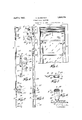
- Figure 1 is a front elevation showing one form of my present invention as applied in practical use
- Fig. 2 is an edge View of one of theadjusting devices, the guide member being shown partly in section;
- Fig. 3 is a side elevation of the adjusting device
- Fig. 4 is a detail fragmentary elevation of the other adjusting device showing the mounting of the said bracket upon the guide member
- Fig. 5 is a horizontal sectional view on an enlarged scale taken on the line 5-5 of Fig. 6 is a similar sectional View taken on the line 6-6 of Fig. 3;
- Fig. 7 is an enlarged detail View of the latch means for the adjustable bracket and its actuating member, illustrating the manner of releasing the same to effect adjustment of the bracket;
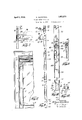
- Fig. 8 is an enlarged fragmentary frontelevation of a windowhaving a slightly modified form of the device applied thereto;
- Fig. 9 is an enlarged side elevation partly broken away in such modified construction.
- Fig. 10 is a fragmentary elevation on an enlarged scale partly in section, showing the modified form of latch means and actuating member;
- Fig. 11 is a longitudinal sectional View taken on the line 1111 of Fig. 10, and
- Fig. 12 is a horizontal sectional view taken on the line 12-12 of Fig. 10.
- each of these devices includes a vertically extending guide base wall of the channel shaped guide to receive an attaching screw indicated at 12.
- These screws may be either of the conventional type having a kerfed head to receive the bit of a screw-driver or they may be provided with winged heads as illustrated whereby they may be conveniently manipulated by hand without theme of a tool.
- each bracket has a lower part 15, 16 respectively, and an upwardly projecting part 17 and 18 respectively.
- These upper and lower spaced parts of the bracket 13 are provided with the usual vertically extending slots 19 to receive the rectangular spring winding trunnions at one end of the rollers of the upper and lower shades S and S respectively.
- the upper and lower parts of the other bracket 14 are provided with the usual circular openings 20 therein to receive the cylindrical studs projecting from the opposite ends of the respective shade rollers.
- Each bracket member is integrally connected with and angularly offset from the plane of an elongated plate 21 which xtends over the open side of the channel shaped guide 8 and is supported upon the iii-turned flanges 9 thereof.
- the angular offset 22 which connects the bracket member with one end of the plate 21 closely overlies one of the side walls of the guide 8 and the bracket member is thus positioned closely adjacent to the surface of the window frame and in inwardly projecting relation to the guide 8.
- lVhile various means may be used for slidahly retaining the plate 8 in connection with the guide, one simple and convenient means for this purpose may comprise the bent lugs or tongues 23 struck inwardly from the plate 21 and extending in opposite directions under the inwardly extendingfianges 9 of the guide.
- a pair of such retaining lugs is provided at the opposite ends of the plate 21.
- an actuating 111.63% her for the shade supporting bracket in the form of a long substantially rigid metal bar 24 is slidably disposed in the channel of each guide member.
- This bar may be of slightly less width than the internal width of the guide so that frictional contact between said bar and the side walls of the guide will not resist or retardthe free vertical sliding movement of said bar.
- the bar 24 at its upper end is provided with an angularly projecting lug 25 which is engaged in a suitable formed opening 26 provided in the lower end of the plate 21.
- the bar 24 is also provided with an outwardly projecting part 27 extending between the flanges 9 of the guide and terminating in a relatively wide finger piece 28.
- the part 27 is provided with an opening 29 therethrough to receive a resilient wire latch element 30.
- the upper end of said wire element above part 29 terminates in a resiliently acting coil 31 which is positioned between the outer face of the bar 24 and the flanges 9 on the guide 8. This coil by its expansion has frictional gripping engagement against the opposite side walls of the guide to thereby prevent lateral shifting movement of the barrelative to the guide and noise incident to contact therewith.
- the wire latch element 30 has a vertically positioned coil 32 formed therein and a finger engaging loop 33 projecting outwardly from said coil.
- the other terminal of the wire at the other end of the loop 33 extends within the channel of the guide 8, said terminal being upwardly curved and angularly bent as at 34 for frictional gripping contact against the inner side of one of the guide flanges 9.
- the spring coil 32 normally acts to urge the loop 33 downwardly and maintain such gripping contact of the wire end 34 with the guide flange, whereby vertical shifting movement of the bar 24 and the shade bracket relative to the guide under the weight of the shade supported by the bracket, is prevented. This effective latched condition of the parts is illustrated in Fig. 2 of the drawings.
- the user when it is desired to lower the top sash 5 to obtain ventilation, the user simultaneously engages the finger pieces 28 and the latch loops 33 at each side of the window with the thumb and for finger of his hands as shown in Figs. and 7 by contact of the finger piece 28 with the lower stop block 10 of the guide.
- the upper sash 5 of the window may now be lowered until its upper edge is slightly above the upper sash S, thus insuring adequate ventilation without blowing or flapping of the window shades.
- I preferably provide a chain or other connecting element indicated at 35 extending between the brackets 13 and 14-.
- This element may be permanently at tached at one of its ends to one of the brackets and provided with means for detachable connection at its other end to the other bracket and might be otherwise located than as indicated in the drawings so as to render the same more or less inconspicuous.
- the actuating member consists of a stiff wire rod 36 arranged in the channel of the fixed guide 8 and having a :1 upper portion 37 extending at an inclination outwardly througl'i the open side oi the guide and terminating in a hook or angularly bent arm 38 which extends in wardly through the opening 26 in the lower end of the bracket carrying plate 21 and is resiliently urged into engagen'ient with the base wall of the guide.
- said wire rod is formed with a narrow later ally ofiset loop 39, the lower side of which joins the upper portion of a relatively wide loop 40 which is laterally offset in the opposite direction with respect to the loop 39.
- the intermediate 'iortions of these two loops have frictional sliding engagement with the opposite longitudinal side walls of the guide 8.
- the rod 36 is extended downwardly along one of the side walls of the guide and beneath its in-turned flange 9 and below said guide, the lower end of the rod terminating in a suitable linger piece indicated at ll.
- the stop members 10 may consist of U-shaped metal plates inserted between the edges of the guide flanges 9.
- the wire rod 36 extending downwardly between one side of the lower stop 10 and the adjacent side wall of the guide 8, is held thereby in its proper relation to the side wall of the guide member and against inward displacement.
- the shade brackets and the plates 21 are retained in adjusted position by means of the member 42.
- This member preferably consists oi" a length of heavy spring wire having a central portion formed into the spring coils 43 from opposite sides of which, the comparatively long arms 44 extend downwardly and are urged by said spring coils 43 in relatively opposite directions into tight fronal hearing contact with the opposite longitudinal side walls of the guide 8.
- the spring coils 43 are located in registering relation with the opening 26 of the bracket carryine; plate 21 and the angular arm or hook 38 of the rod 36 extends through said coils.
- a shade supporting bracket comprising a sheet metal plate extending longitudinally over the open side of the guide strip channel exteriorly thereof, said plate and the side walls of the guide strip having cooperatlng means 1ntegrally formed thereon and retainingthe 3 bracket in slidable connection with said strip,
- a shade roller supporting arm integral with one end of said plate disposed in ofiset parallel relation to the plane of said plate and resiliently yieldable relative to the plate and guide strip, and manually operable means within the channel of the guide strip connected to the other end of said plate for adjusting the bracket relative to the guide strip.
- a shade supporting bracket comprising an elongated sheet metal plate extending longitudinally over the open side of the guide strip channel exteriorly thereof, said plate and the side walls of the guide strip having cooperating means thereon to retain the bracket in slidable connection with said strip, said bracket plate and the guide strip being adapted to flex as a unit in attaching the guide strip to the window frame, a shade roller supporting arm integral with one end of said plate disposed in offset parallel relation to the plane of said plate and projecting longitudinally beyond one end thereof to resiliently H 3.
- a channel shaped, sheet metal guide strip adapted to be secured to the window frame, a shade supporting bracket comprising a sheet metal plate having an integral shade supporting arm atone end laterally offset from said plate and disposed in a plane parallel therewth, said guide strip having inward- 1y projecting flanges on its sidewalls, and
- bracket plate extending longitudinally upon the outer sides of said flanges over the open side of the channel and having integrally formed tongues at its opposite ends cooperating with said flanges to retain the bracket in slida-ble connection with the guide strip, and means mounted on the guide strip and connected to the other end of said plate for adjusting the bracket relative to the guide strip.
- a shade supporting bracket comprising a plate extending longitudinally along one side of said strip, and means connecting said plate to the guide strip for longitudinal sliding movement thereon, said plate at one of its ends having an angularly disposed part extending longitudinally over one edge of the guide strip in closely adjacent relation thereto, and a shade roller supporting arm integrally formed with said part, bendable relative thereto and disposed substantially in the plane of said guide strip.
Description
April 5, 1932. N. SLOBOTKIN WINDOW SHADE ADJUSTER Filed Dec. 6, 1950 '2 Sheets-Sheet l zzt .m 1 Y 4 i w w]. mfi m a m 5 1 N April 5, 1932. N. SLOBOTKIN 1,852,270
WINDOW SHADE ADJUSTER Filed Dec. 6, 1930 2 Sheets-Sheet 2 E i .9 z a I l l/ZZ 1 i E mml i rlllll llflilIIIIHHIHIIHIHIII Patented Apr. 5, 1932 UNITED STATES PATENT OFFICE \VINDOW SHADE ADJUSTER Application filed December 6, 1920. Serial No. 500,476.
This invention relates to an improved window shade adjuster, and has for its general object and purpose to provide a simply constructed, durable and easily applied device l"; of this kind for supportingthe window shade for bodily vertical movement relative to the window sash and frame so that the shade may be easily lowered to an adjusted position for the purpose of obtaining ventilation at the top of the window and avoiding flapping of the frame by strong air currents and possible injury thereto.
In one practical embodiment of the invention, I provide vertical guides adapted to be attached to the opposite sides of the window frame and shade supporting brackets slidably mounted upon said guides. It is one of the important objects of the invention to provide novel, simply constructed and very effective means for securely looking or holding the brackets in their adjusted positions upon the respective guides.
The invention has for an additional object to provide a very simple and inexpensive construction of the bracket guides together with novel means for slidably mounting the brackets upon said guides.
Another object of the invention is to provide actuating means for the brackets slidahly mounted in the respective guides and cooperating therewith so as to permit of their free relative movement while preventing vibration or chattering metallic contact with the guides.
It is also a further object of the invention to provide improved means for restraining the shade brackets in their vertical adjustment against movement to such positions out of horizontal alignment with each other as would release one end of the shade whereby the same would become detached from the brackets.
With the above and other objects in view, the invention consists in the improved adjusting means for window shades, and in the form, construction and relative arrangement of the several parts thereof as will be hereinafter more fully described, illustrated in the accompanying drawings, and subsequently incorporated in the subjoined claims.
In the drawings, wherein I have disclosed several simple and practical embodiments of the invention, and in which similar reference characters designate corresponding parts throughout the several views,
Figure 1 is a front elevation showing one form of my present invention as applied in practical use;
Fig. 2 is an edge View of one of theadjusting devices, the guide member being shown partly in section;
Fig. 3 is a side elevation of the adjusting device;
Fig. 4 is a detail fragmentary elevation of the other adjusting device showing the mounting of the said bracket upon the guide member Fig. 5 is a horizontal sectional view on an enlarged scale taken on the line 5-5 of Fig. 6 is a similar sectional View taken on the line 6-6 of Fig. 3;
Fig. 7 is an enlarged detail View of the latch means for the adjustable bracket and its actuating member, illustrating the manner of releasing the same to effect adjustment of the bracket;
Fig. 8 is an enlarged fragmentary frontelevation of a windowhaving a slightly modified form of the device applied thereto;
Fig. 9 is an enlarged side elevation partly broken away in such modified construction;
Fig. 10 is a fragmentary elevation on an enlarged scale partly in section, showing the modified form of latch means and actuating member;
Fig. 11 is a longitudinal sectional View taken on the line 1111 of Fig. 10, and
Fig. 12 is a horizontal sectional view taken on the line 12-12 of Fig. 10.
Referring in detail to the drawings, for purposes of illustration, I have shown the conventional upper and lower window sashes 5 and 6 slidably mounted in the frame Upon the inner side of the window frame and upon the opposite vertical parts thereof, my improved shade adjusting devices are mounted. As herein shown, each of these devices includes a vertically extending guide base wall of the channel shaped guide to receive an attaching screw indicated at 12. These screws may be either of the conventional type having a kerfed head to receive the bit of a screw-driver or they may be provided with winged heads as illustrated whereby they may be conveniently manipulated by hand without theme of a tool.
Upon each of the guides 8, a shade supporting bracket 13 and 14 respectively, is
slidably mounted. While these brackets may be provided with means to support only a single shade, as herein shown, each bracket has a lower part 15, 16 respectively, and an upwardly projecting part 17 and 18 respectively. These upper and lower spaced parts of the bracket 13 are provided with the usual vertically extending slots 19 to receive the rectangular spring winding trunnions at one end of the rollers of the upper and lower shades S and S respectively. The upper and lower parts of the other bracket 14 are provided with the usual circular openings 20 therein to receive the cylindrical studs projecting from the opposite ends of the respective shade rollers.
Each bracket member is integrally connected with and angularly offset from the plane of an elongated plate 21 which xtends over the open side of the channel shaped guide 8 and is supported upon the iii-turned flanges 9 thereof. The angular offset 22 which connects the bracket member with one end of the plate 21 closely overlies one of the side walls of the guide 8 and the bracket member is thus positioned closely adjacent to the surface of the window frame and in inwardly projecting relation to the guide 8.
lVhile various means may be used for slidahly retaining the plate 8 in connection with the guide, one simple and convenient means for this purpose may comprise the bent lugs or tongues 23 struck inwardly from the plate 21 and extending in opposite directions under the inwardly extendingfianges 9 of the guide. Preferably, a pair of such retaining lugs is provided at the opposite ends of the plate 21.
In the embodiment of the invention shown in Figs. 1 to 7 inclusive, an actuating 111.63% her for the shade supporting bracket in the form of a long substantially rigid metal bar 24 is slidably disposed in the channel of each guide member. This bar may be of slightly less width than the internal width of the guide so that frictional contact between said bar and the side walls of the guide will not resist or retardthe free vertical sliding movement of said bar. The bar 24 at its upper end is provided with an angularly projecting lug 25 which is engaged in a suitable formed opening 26 provided in the lower end of the plate 21. At its lower end, the bar 24 is also provided with an outwardly projecting part 27 extending between the flanges 9 of the guide and terminating in a relatively wide finger piece 28. The part 27 is provided with an opening 29 therethrough to receive a resilient wire latch element 30. The upper end of said wire element above part 29 terminates in a resiliently acting coil 31 which is positioned between the outer face of the bar 24 and the flanges 9 on the guide 8. This coil by its expansion has frictional gripping engagement against the opposite side walls of the guide to thereby prevent lateral shifting movement of the barrelative to the guide and noise incident to contact therewith.
Beneath the finger piece 8 and at the inner end thereof, the wire latch element 30 has a vertically positioned coil 32 formed therein and a finger engaging loop 33 projecting outwardly from said coil. The other terminal of the wire at the other end of the loop 33 extends within the channel of the guide 8, said terminal being upwardly curved and angularly bent as at 34 for frictional gripping contact against the inner side of one of the guide flanges 9. The spring coil 32 normally acts to urge the loop 33 downwardly and maintain such gripping contact of the wire end 34 with the guide flange, whereby vertical shifting movement of the bar 24 and the shade bracket relative to the guide under the weight of the shade supported by the bracket, is prevented. This effective latched condition of the parts is illustrated in Fig. 2 of the drawings.
Assuming that the adjusting devices as above described have been attached to the window frame, and that the shades are supported in the brackets 13 and 14 at the top of the window as shown in Fig. 1, when it is desired to lower the top sash 5 to obtain ventilation, the user simultaneously engages the finger pieces 28 and the latch loops 33 at each side of the window with the thumb and for finger of his hands as shown in Figs. and 7 by contact of the finger piece 28 with the lower stop block 10 of the guide. The upper sash 5 of the window may now be lowered until its upper edge is slightly above the upper sash S, thus insuring adequate ventilation without blowing or flapping of the window shades.
F or the purpose or limiting the extent to which the brackets 13 and let might be adj usted out of horizontal alignment with each other to thereby prevent the release of the shade roller trunnions from supporting contact upon said brackets, I preferably provide a chain or other connecting element indicated at 35 extending between the brackets 13 and 14-. This element may be permanently at tached at one of its ends to one of the brackets and provided with means for detachable connection at its other end to the other bracket and might be otherwise located than as indicated in the drawings so as to render the same more or less inconspicuous. By the provision oi such a connecting member, it will be readily seen that the extent to which one oi. the shade brackets might be vertically raised or lowered above or below the position of the other bracket, will be definitely limited so that the possibility of the detachment of the shade from the supporting brackets is obviated.
In Figs. 8 to 12 of the drawings, I have illustrated a slightly modified form of the actuating means for the adjustable brackets and the means for retaining said brackets in adjusted position. In this construction, the actuating member consists of a stiff wire rod 36 arranged in the channel of the fixed guide 8 and having a :1 upper portion 37 extending at an inclination outwardly througl'i the open side oi the guide and terminating in a hook or angularly bent arm 38 which extends in wardly through the opening 26 in the lower end of the bracket carrying plate 21 and is resiliently urged into engagen'ient with the base wall of the guide. Within the channel of the guide at the lower end of the part 37, said wire rod is formed with a narrow later ally ofiset loop 39, the lower side of which joins the upper portion of a relatively wide loop 40 which is laterally offset in the opposite direction with respect to the loop 39. The intermediate 'iortions of these two loops have frictional sliding engagement with the opposite longitudinal side walls of the guide 8. From the lower loop 40, the rod 36 is extended downwardly along one of the side walls of the guide and beneath its in-turned flange 9 and below said guide, the lower end of the rod terminating in a suitable linger piece indicated at ll. As shown in connection with this construction, the stop members 10 may consist of U-shaped metal plates inserted between the edges of the guide flanges 9. They may be either welded to said flanges or merely friction ally held thereby to be rigidly fixed in place by the attaching screws. The wire rod 36 extending downwardly between one side of the lower stop 10 and the adjacent side wall of the guide 8, is held thereby in its proper relation to the side wall of the guide member and against inward displacement.
In the above described modified construction, the shade brackets and the plates 21 are retained in adjusted position by means of the member 42. This member preferably consists oi" a length of heavy spring wire having a central portion formed into the spring coils 43 from opposite sides of which, the comparatively long arms 44 extend downwardly and are urged by said spring coils 43 in relatively opposite directions into tight fronal hearing contact with the opposite longitudinal side walls of the guide 8. The spring coils 43 are located in registering relation with the opening 26 of the bracket carryine; plate 21 and the angular arm or hook 38 of the rod 36 extends through said coils.
In the above described construction, it will. be understood that when the bracket members are at the limit of their upward movement on their respective guides, the finger pieces 41 of the actuating members 36 are disposed externally of said guides below the same. Thus, from reference to Fig. 8 of the drawings, it will be seen that these finger pieces may be readily reached and grasped by a child or person of comparatively short stature, since they are located approximately at the upper rail of the lower sash. When the actuating' members or rods 36 are pulled downwardly, the frictional resistance to such move ment offered by the loop portions 39 and 40 of the rod and the spring arms 44 is overcome. This frictional resistance is however, ample to sustain the adjustable guides in their adjusted positions under the weight of the shade rollers. The engagement of the lower side of the loop 40 in the actuating rod 36 with the lower stop member 10, limits the extent of downward movement of the bracket members.
From the foregoing description considered in connection with the accompanying drawings, the construction, manner of operation and several advantages of my invention as herein described willbe clearly understood. It will be seen that such a device may be easily and quickly applied to the ordinary window by the householder, without requiring the assistance of a skilled workman. In order that the device may be readily substituted for different forms of shade supportin brackets heretofore in general use, it may be necessary to make certain adjustments. Thus, the parts 15 and 17 of the'brackets can be readily adjusted by bending the same from the angula r offset 22 of the plate 21 in accordance with the length of the shade roller so as to insure a secure engagement of the roller trunnions in the openings and slots of the bracket members. In some instances, it may be possible to apply my present invention, without first requiring the removal of the old shade supportin brackets.
Since the channelled guide 8 and the shade supporting brackets mounted thereon are of themselves to the variable frame width and insuring entire freedom of the shade roller from excessive binding in any adjusted position of the brackets.
I have illustrated and described in more or less detail, two embodiments of my present improvements, which I have found to be entirely satisfactory in practical use. However,
it is to be understood that the form and construction of the guides as well as the shade brackets and the actuating means therefor may also be produced in various other alternative structural forms. Therefore, as to the essential features of my present disclosure,
I reserve the privilege of adopting all such legitimate changes therein as may be fairly included within the spirit and scope of the invention as claimed.
GOI
I claim:
1. In window shade adjusting means, a channel shaped sheet metal guide strip adapted to be secured to the window frame, a shade supporting bracket comprising a sheet metal plate extending longitudinally over the open side of the guide strip channel exteriorly thereof, said plate and the side walls of the guide strip having cooperatlng means 1ntegrally formed thereon and retainingthe 3 bracket in slidable connection with said strip,
a shade roller supporting arm integral with one end of said plate disposed in ofiset parallel relation to the plane of said plate and resiliently yieldable relative to the plate and guide strip, and manually operable means within the channel of the guide strip connected to the other end of said plate for adjusting the bracket relative to the guide strip.
2. In window shade adjusting means, a channel shaped, sheet metal guide strip, a shade supporting bracket comprising an elongated sheet metal plate extending longitudinally over the open side of the guide strip channel exteriorly thereof, said plate and the side walls of the guide strip having cooperating means thereon to retain the bracket in slidable connection with said strip, said bracket plate and the guide strip being adapted to flex as a unit in attaching the guide strip to the window frame, a shade roller supporting arm integral with one end of said plate disposed in offset parallel relation to the plane of said plate and projecting longitudinally beyond one end thereof to resiliently H 3. In window shade adjusting means, a channel shaped, sheet metal guide strip adapted to be secured to the window frame, a shade supporting bracket comprising a sheet metal plate having an integral shade supporting arm atone end laterally offset from said plate and disposed in a plane parallel therewth, said guide strip having inward- 1y projecting flanges on its sidewalls, and
said bracket plate extending longitudinally upon the outer sides of said flanges over the open side of the channel and having integrally formed tongues at its opposite ends cooperating with said flanges to retain the bracket in slida-ble connection with the guide strip, and means mounted on the guide strip and connected to the other end of said plate for adjusting the bracket relative to the guide strip. 7
4. In window shade adjusting means, a guide strip, a shade supporting bracket comprising a plate extending longitudinally along one side of said strip, and means connecting said plate to the guide strip for longitudinal sliding movement thereon, said plate at one of its ends having an angularly disposed part extending longitudinally over one edge of the guide strip in closely adjacent relation thereto, and a shade roller supporting arm integrally formed with said part, bendable relative thereto and disposed substantially in the plane of said guide strip.
In testimony that I claim the foregoing as my invention, I have signed my name hereto.
NATHAN SLOBOTKIN.
Priority Applications (1)
| Application Number | Priority Date | Filing Date | Title |
|---|---|---|---|
| US500476A US1852270A (en) | 1930-12-06 | 1930-12-06 | Window shade adjuster |
Applications Claiming Priority (1)
| Application Number | Priority Date | Filing Date | Title |
|---|---|---|---|
| US500476A US1852270A (en) | 1930-12-06 | 1930-12-06 | Window shade adjuster |
Publications (1)
| Publication Number | Publication Date |
|---|---|
| US1852270A true US1852270A (en) | 1932-04-05 |
Family
ID=23989574
Family Applications (1)
| Application Number | Title | Priority Date | Filing Date |
|---|---|---|---|
| US500476A Expired - Lifetime US1852270A (en) | 1930-12-06 | 1930-12-06 | Window shade adjuster |
Country Status (1)
| Country | Link |
|---|---|
| US (1) | US1852270A (en) |
Cited By (1)
| Publication number | Priority date | Publication date | Assignee | Title |
|---|---|---|---|---|
| EP1655446A1 (en) * | 2004-11-08 | 2006-05-10 | Grosfillex SAS | Device and method for inserting a roller blind to the upper beam of a frame |
-
1930
- 1930-12-06 US US500476A patent/US1852270A/en not_active Expired - Lifetime
Cited By (2)
| Publication number | Priority date | Publication date | Assignee | Title |
|---|---|---|---|---|
| EP1655446A1 (en) * | 2004-11-08 | 2006-05-10 | Grosfillex SAS | Device and method for inserting a roller blind to the upper beam of a frame |
| FR2877688A1 (en) * | 2004-11-08 | 2006-05-12 | Grosfillex Sarl Sarl | DEVICE AND METHOD FOR THE INSTALLATION OF A ROLLING SHUTTER PARTLY HIGH OF A HINGE |
Similar Documents
| Publication | Publication Date | Title |
|---|---|---|
| US1852270A (en) | Window shade adjuster | |
| US2015993A (en) | Universal rolling window screen | |
| US1702395A (en) | Window-screen clamp | |
| US1528910A (en) | Curtain bracket | |
| US2738154A (en) | Hanger | |
| US1983467A (en) | Adjustable device for curtains and draperies | |
| US2568001A (en) | Bracket for venetian blinds | |
| US1564328A (en) | Combined shade and curtain fixture | |
| US2587902A (en) | Guide spring for combination storm windows and screens | |
| US2435109A (en) | Sheet metal curtain rod | |
| US2105482A (en) | Detachable curtain rod bracket | |
| US2555819A (en) | Bracket | |
| US2137444A (en) | Venetian blind | |
| US1905979A (en) | Venetian blind | |
| US2492867A (en) | Window suspension means for venetian blinds | |
| US2244790A (en) | Adjustable support | |
| US1553911A (en) | Shade and curtain holder | |
| US1489987A (en) | Mounting device for shade fixtures | |
| US1413731A (en) | Shade raiser | |
| US1520066A (en) | Combination shade and curtain hanger | |
| US1878773A (en) | Window shade bracket | |
| US1535591A (en) | Window-shade roll and holder therefor | |
| US1843014A (en) | Combined shade and curtain bracket | |
| US961230A (en) | Window-shade hanger. | |
| US1108681A (en) | Window-shade support. |