US1852092A - Roll - Google Patents
Roll Download PDFInfo
- Publication number
- US1852092A US1852092A US540953A US54095331A US1852092A US 1852092 A US1852092 A US 1852092A US 540953 A US540953 A US 540953A US 54095331 A US54095331 A US 54095331A US 1852092 A US1852092 A US 1852092A
- Authority
- US
- United States
- Prior art keywords
- roll
- shaft
- halves
- twisters
- set screw
- Prior art date
- Legal status (The legal status is an assumption and is not a legal conclusion. Google has not performed a legal analysis and makes no representation as to the accuracy of the status listed.)
- Expired - Lifetime
Links
- 241001589086 Bellapiscis medius Species 0.000 description 8
- 239000002184 metal Substances 0.000 description 5
- 229910000831 Steel Inorganic materials 0.000 description 3
- 239000010959 steel Substances 0.000 description 3
- 239000007799 cork Substances 0.000 description 2
- 239000010985 leather Substances 0.000 description 2
- 230000015572 biosynthetic process Effects 0.000 description 1
- 238000010276 construction Methods 0.000 description 1
- 238000003754 machining Methods 0.000 description 1
- 230000004048 modification Effects 0.000 description 1
- 238000012986 modification Methods 0.000 description 1
- 238000010079 rubber tapping Methods 0.000 description 1
- 238000003466 welding Methods 0.000 description 1
Images
Classifications
-
- D—TEXTILES; PAPER
- D03—WEAVING
- D03D—WOVEN FABRICS; METHODS OF WEAVING; LOOMS
- D03D49/00—Details or constructional features not specially adapted for looms of a particular type
- D03D49/04—Control of the tension in warp or cloth
- D03D49/20—Take-up motions; Cloth beams
-
- Y—GENERAL TAGGING OF NEW TECHNOLOGICAL DEVELOPMENTS; GENERAL TAGGING OF CROSS-SECTIONAL TECHNOLOGIES SPANNING OVER SEVERAL SECTIONS OF THE IPC; TECHNICAL SUBJECTS COVERED BY FORMER USPC CROSS-REFERENCE ART COLLECTIONS [XRACs] AND DIGESTS
- Y10—TECHNICAL SUBJECTS COVERED BY FORMER USPC
- Y10S—TECHNICAL SUBJECTS COVERED BY FORMER USPC CROSS-REFERENCE ART COLLECTIONS [XRACs] AND DIGESTS
- Y10S474/00—Endless belt power transmission systems or components
- Y10S474/903—Particular connection between hub and shaft
Definitions
- My invention relates to improvements in rolls for use in connection with twisters, looms, etc., being particularly directed to take-up rolls for twisters, these rolls which are covered with cork or leather being employed for the purpose of determining the gathering speed of the thread.
- One of the objects of my invention is to provide a roll comparatively light in weight
- a further object of my invention is the provision of a roll so constructed that the leather or cork covering can be readily applied thereto without any machining operation.
- FIG. 1 is an end view of my improved roll
- Fig. 2 is a section on line 2-2 of Fig. 1, and
- Fig. 3 is an elevational View.
- 1 and 2 designate two halves of my improved roll, these halves, which are identical, each being provided with a groove or half cylinder designated 3 and 4 respectively.
- the roll is of pressed steel and these grooves are pressed into the web 5 of each half of the roll when the roll is being formed to provide a cylinder 6 perpendicular to the axis of the roll when the two halves are secured together.
- This cylinder is later tapped for receiving a set screw 7 whereby the roll may be securely fastened to the shaft 8 on which the roll is to be mounted.
- the two halves 1 and 2 of the roll are stamped from pressed steel, and may be secured to each other in any suitable manner, as by spot welding as indicated at 9, 10, 11, 12 and 13.
- spot welding as indicated at 9, 10, 11, 12 and 13.
- Each web 5 of the roll halves 1 and 2 is provided with hollow conical hubs let and 15, respectively, to provide a construction in which only the annular flanges lo and 17 of the hubs engage the shaft 8 on which the roll 1931.
- a sheet metal take-up roll for twisters comprising two stampings each of which provides one half of the roll and one half of a hole for a set screw, and means for securing the two stampings together.
- a sheet metal take-up roll for twisters comprising two stampings each stamping comprising one half of the roll and having a groove therein extending perpendicular to the axis of the roll, and providing one half of a hole for a set screw, each stamping being provided centrally with a conical hub formation providing one half of the roll hub, and means for securing the two stampings together.
- a sheet metal take-up roll for twisters comprising two identical halves, each half being shaped to provide one half of a hole for a set screw extending perpendicular to the axis of the roll, said halves being spot welded to each other.
- a sheet metal take-up roll for twisters comprising two identical halves shaped to provide a hole for a set screw perpendicular to the axis of the roll and to provide a hub for receiving a shaft on which the roll is mounted, said halves being spot welded to each other, said hub being so shaped as to contact with the shaft only at points spaced equidistant from the center of said roll.
- a take-up roll for twisters comprising two pressed steel parts each comprising a cylindrical outer portion, a fiat web portion, a conical hub portion and a cylindrical portion perpendicular to the axis of the roll and means for securing the two parts together.
- a take-up roll for twisters comprising two sheet metal parts each comprising a cylindricalouter portion and an end portion, each of said end portions having a groove to provide a hole perpendicular to the axis of the roll, said end portions each being provided centrally with a conical hub portion having an annular ,fiange thereon, a shaft passing through the said hub portions and engaging the same at said annularfianges only, and a set screw in said hole engaging said shaft intermediate the points of engagement of the shaft with said annular flanges.
Landscapes
- Engineering & Computer Science (AREA)
- Textile Engineering (AREA)
- Reduction Rolling/Reduction Stand/Operation Of Reduction Machine (AREA)
Description
April 5, 15532. 0. w. SCHAUM 2 ROLL Filed May 29, 1931 IN VEN TOR.
0 W/SCHAUM Patented Apr. 5, 1932 r orr= oTTo w. SCHAUM, or PHILADELPHIA, PENNsYLVANIA, sssienoa To FLETCHER WORKS, INCORPORATED, OF PHILADELPHIA,
OF PENNSYLVANIA PENNSYLVANIA, A C RP R I ROLL Application filed May 29,
My invention relates to improvements in rolls for use in connection with twisters, looms, etc., being particularly directed to take-up rolls for twisters, these rolls which are covered with cork or leather being employed for the purpose of determining the gathering speed of the thread.
One of the objects of my invention is to provide a roll comparatively light in weight,
resulting in a direct saving in power, and a roll which can be held more securely on the shaft than rolls as heretofore constructed.
A further object of my invention is the provision of a roll so constructed that the leather or cork covering can be readily applied thereto without any machining operation.
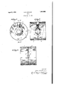
In the accompanying drawings Fig. 1 is an end view of my improved roll;
Fig. 2 is a section on line 2-2 of Fig. 1, and
Fig. 3 is an elevational View.
Referring to the drawings in detail, 1 and 2 designate two halves of my improved roll, these halves, which are identical, each being provided with a groove or half cylinder designated 3 and 4 respectively. The roll is of pressed steel and these grooves are pressed into the web 5 of each half of the roll when the roll is being formed to provide a cylinder 6 perpendicular to the axis of the roll when the two halves are secured together. This cylinder is later tapped for receiving a set screw 7 whereby the roll may be securely fastened to the shaft 8 on which the roll is to be mounted.
As above noted the two halves 1 and 2 of the roll are stamped from pressed steel, and may be secured to each other in any suitable manner, as by spot welding as indicated at 9, 10, 11, 12 and 13. When the two halves of the roll are secured together the grooves or half cylinders 3 and 4 will be in register whereby the tapping of the cylinder can be readily accomplished.
Each web 5 of the roll halves 1 and 2 is provided with hollow conical hubs let and 15, respectively, to provide a construction in which only the annular flanges lo and 17 of the hubs engage the shaft 8 on which the roll 1931. Serial No. 540,953.
shaft is engaged by the roll for the full length of the hole in the roll and the set screw presses the shaft against the hub withmaximum pressure at a point directly opposite the set screw giving a two-point contact with the ever constant danger of the roll working loose and slipping on the shaft.
l/Vhile I have illustrated and described a preferred embodiment of my invention it is to be understood that various changes and modifications may be made therein without departing fromthe spirit and scope of my invention. Q
What I claim is 1. A sheet metal take-up roll for twisters comprising two stampings each of which provides one half of the roll and one half of a hole for a set screw, and means for securing the two stampings together.
2. A sheet metal take-up roll for twisters comprising two stampings each stamping comprising one half of the roll and having a groove therein extending perpendicular to the axis of the roll, and providing one half of a hole for a set screw, each stamping being provided centrally with a conical hub formation providing one half of the roll hub, and means for securing the two stampings together.
3. A sheet metal take-up roll for twisters comprising two identical halves, each half being shaped to provide one half of a hole for a set screw extending perpendicular to the axis of the roll, said halves being spot welded to each other.
4. A sheet metal take-up roll for twisters comprising two identical halves shaped to provide a hole for a set screw perpendicular to the axis of the roll and to provide a hub for receiving a shaft on which the roll is mounted, said halves being spot welded to each other, said hub being so shaped as to contact with the shaft only at points spaced equidistant from the center of said roll.
5. A take-up roll for twisters comprising two pressed steel parts each comprising a cylindrical outer portion, a fiat web portion, a conical hub portion and a cylindrical portion perpendicular to the axis of the roll and means for securing the two parts together.
6. A take-up roll for twisters comprising two sheet metal parts each comprising a cylindricalouter portion and an end portion, each of said end portions having a groove to provide a hole perpendicular to the axis of the roll, said end portions each being provided centrally with a conical hub portion having an annular ,fiange thereon, a shaft passing through the said hub portions and engaging the same at said annularfianges only, and a set screw in said hole engaging said shaft intermediate the points of engagement of the shaft with said annular flanges.
This specification signed this 27th day of May, 1931.
' OTTO W. SCHAUM.
Priority Applications (1)
| Application Number | Priority Date | Filing Date | Title |
|---|---|---|---|
| US540953A US1852092A (en) | 1931-05-29 | 1931-05-29 | Roll |
Applications Claiming Priority (1)
| Application Number | Priority Date | Filing Date | Title |
|---|---|---|---|
| US540953A US1852092A (en) | 1931-05-29 | 1931-05-29 | Roll |
Publications (1)
| Publication Number | Publication Date |
|---|---|
| US1852092A true US1852092A (en) | 1932-04-05 |
Family
ID=24157581
Family Applications (1)
| Application Number | Title | Priority Date | Filing Date |
|---|---|---|---|
| US540953A Expired - Lifetime US1852092A (en) | 1931-05-29 | 1931-05-29 | Roll |
Country Status (1)
| Country | Link |
|---|---|
| US (1) | US1852092A (en) |
Cited By (1)
| Publication number | Priority date | Publication date | Assignee | Title |
|---|---|---|---|---|
| US4193310A (en) * | 1978-11-13 | 1980-03-18 | Illinois Tool Works Inc. | Idler pulley |
-
1931
- 1931-05-29 US US540953A patent/US1852092A/en not_active Expired - Lifetime
Cited By (1)
| Publication number | Priority date | Publication date | Assignee | Title |
|---|---|---|---|---|
| US4193310A (en) * | 1978-11-13 | 1980-03-18 | Illinois Tool Works Inc. | Idler pulley |
Similar Documents
| Publication | Publication Date | Title |
|---|---|---|
| US2724975A (en) | Pressed steel pulley | |
| US2811322A (en) | Cable winding clamping apparatus | |
| US1852092A (en) | Roll | |
| US2337308A (en) | Pulley or feed wheel | |
| US1943620A (en) | Land wheel | |
| GB313969A (en) | Improvements in variable-speed gearing | |
| DE326176C (en) | Wheel rim attachment | |
| US1766585A (en) | Driving cylinder for spinning frames | |
| US2130409A (en) | Abrading roller | |
| US2489178A (en) | V-belt sheave | |
| US2357188A (en) | Hub for coaster brakes | |
| US2034862A (en) | Friction winding core | |
| US1825508A (en) | All metal spool | |
| US1033934A (en) | Pulley. | |
| US1911990A (en) | Cotter pin spreader | |
| US1333883A (en) | Roller-bearing eccentric | |
| GB1219156A (en) | A hub and shaft assembly | |
| US1273941A (en) | Brake-band. | |
| US1380670A (en) | Reel or beam | |
| US2610004A (en) | Metal bobbin | |
| US1700593A (en) | Textile spool and bobbin | |
| US1666352A (en) | Split pulley | |
| US1025264A (en) | Pulley. | |
| US1944779A (en) | Multigrooved pulley | |
| US1535369A (en) | Pulley |