US1851979A - Type case - Google Patents
Type case Download PDFInfo
- Publication number
- US1851979A US1851979A US435310A US43531030A US1851979A US 1851979 A US1851979 A US 1851979A US 435310 A US435310 A US 435310A US 43531030 A US43531030 A US 43531030A US 1851979 A US1851979 A US 1851979A
- Authority
- US
- United States
- Prior art keywords
- type
- case
- push plates
- compartments
- stacks
- Prior art date
- Legal status (The legal status is an assumption and is not a legal conclusion. Google has not performed a legal analysis and makes no representation as to the accuracy of the status listed.)
- Expired - Lifetime
Links
- 239000002436 steel type Substances 0.000 description 6
- XAGFODPZIPBFFR-UHFFFAOYSA-N aluminium Chemical compound [Al] XAGFODPZIPBFFR-UHFFFAOYSA-N 0.000 description 2
- 229910052782 aluminium Inorganic materials 0.000 description 2
- 238000010276 construction Methods 0.000 description 2
- 229910000831 Steel Inorganic materials 0.000 description 1
- 238000004519 manufacturing process Methods 0.000 description 1
- 230000004048 modification Effects 0.000 description 1
- 238000012986 modification Methods 0.000 description 1
- 230000000630 rising effect Effects 0.000 description 1
- 239000010959 steel Substances 0.000 description 1
Images
Classifications
-
- B—PERFORMING OPERATIONS; TRANSPORTING
- B41—PRINTING; LINING MACHINES; TYPEWRITERS; STAMPS
- B41B—MACHINES OR ACCESSORIES FOR MAKING, SETTING, OR DISTRIBUTING TYPE; TYPE; PHOTOGRAPHIC OR PHOTOELECTRIC COMPOSING DEVICES
- B41B1/00—Elements or appliances for hand composition; Chases, quoins, or galleys
Definitions
- This invention relates to type cases and has for an object to provide a case for holding type in stacks, the case having novel push plates for selectively ejecting the type from the stacks as needed.
- Another objectof the invention is to provide a small, compact type case for use by postmasters or others who have occasion to change the type in canceling stamps daily or hourly, the case being so constructed as to present a neat appearance and being formed of a few durable parts which are inexpensive to manufacture and will not easily get out of order.
- stamps being made of steel and employing steel type, one type for the name of the month, one for the date, one for the hour and another for the year, making four in all.
- Steel type is comparatively large and heavy and it is therefore a further object of my invention to provide a case for conveniently holding such type and having means for positively ejecting the type as needed.
- Figure 1 is a perspective view showing a type case constructed in accordance with my invention
- Figure 2 is a longitudinal sectional view taken on the line 22 of Figure 1 with one side wall removed, 7
- Figure 4 is a cross sectional view taken 4-4 of Figure 2 showing how the push plates operate to eject type, I
- Figure 5 is a detail'perspective view showing the slots formed in the bottom of the removable side wall
- Figure 6 is a detail view showing one form of postmasters stamp having rubber type and used for stamping registered .matter and money orders, 7
- Figure 7 is a perspective view of amodified form of my invention designed to hold steel type, V
- Figure 8 is a cross sectional view taken on the line 8-8 of Figure 7,
- Figure9 is a cross sectional view taken on the line 9-9 of' Figure 8 with the removable side wall removed, and 1 70 Figure 10 is a detail view showing the postmasters canceling stamp using steel type.
- the device is 75 shown to comprise a base 10 which is preferablyform'ed of aluminum and is substan tially rectangular in outline.
- an upright case 11 also preferably formed of aluminum and comprising a side wall 12, end walls 13 and 14, and a side wall 15 which is removably secured to the end wall 14 by means of a screw 16 or otherwise.
- the side wall 15 forms a cover which when removed permits access to the interior of the case.
- the case is provided with integral vertical division walls 17 which divide the interior of the case into compartments adapted to receive type in stacks. As illustrated the case is 90 higher at one end than at the other end so that in the present embodiment,,three tall compartments and three short compartments are formed. The purpose of this is to produce tall compartments for the type 18 bearing the dates of the month, thirty-one in all, while the short compartments may receive type 18' bearing the abbreviation of the name of the month, there being twelve of these.
- the compartments above described are open at the bottom and the end wall l2 is provided between the .dividing walls 17 with a row of slots 19 through which type from :the various stacks may be selectively ejected by mechanism presently described.
- the removableside wall 15 is also provided with slots 20 which communicate with the tops of the compartments formed by the division walls and permit of used type being inserted into the case.
- a pair of push plates 21 and 22 are sup ported on the base 10 and normally close the open bottoms of the compartments.
- Each push plate is formed preferably square 1n outline and is p-rovided at the outer edge with an upturned grip 23 by means of which the plate maybe moved outwardly or inwardly.
- Each plate is provided with longitudinal slots 2-1 which receive the division walls .17, the latter vforming guides to direct the sliding movement of the push plates.
- the removable wall 15 ' is formed with projections '25 which also enter .the slots 24 and coact with the division walls 17 informing guides forthe push plates.
- the spaces between the projections 25 obviously constitute slots 26 which register with the slots 19 in the fixed wall 12 of the case and permit of the push plates being slid through both walls, of the case to eject type from the stacks as will presently be:described.
- a plate 27 is disposed above and houses the push plates.
- the plate 27 is "provided with dependinglugs 28 as shown in Figure 3, which enter slots 29 formed in the push platesand limit movement'of the push plates in either direction.
- the plate "27 is terminally provided'with lugs 30 which inter-fit with corresponding lugs 31 formedon the end walls of the case.
- Bolts 32 are passed through these. interfitting lugs and through thebase and'secure both the case and the push plates to the'base. Removal-of these two bolts permits easy disassembly of the parts.
- a plurality of plungers 33 Disposed in the top wall of the case is a plurality of plungers 33 which are slidably *fitted in the respectivecompartments formed by the division walls 17 and-press the corresponding stacks dcwnwardly so that the inatural stickiness inherent in rubber type will be overcome and the type urged downwardly to'dispose the lowermost type in position for ejection when the push plates are operated.
- a helical spring 34 is seated on the stem 35 of each plunger and presses against the top wall of the casing. The stem 35 of each plunger projects above the.
- a knob 86 by means of which the plunger may be elevated against the tension of the spring 34, the knob being equipped with a collar 37 which engages the top of the case and limits downwardly movement of the plunger under the action of its spring.
- the plungers are normally held below the feed slots 20 above described and shown best in Figure l and must be raised by means of the knobs 36 when it is desired to replenish the stacks.
- the push plate 22 forms a bottom for the type compartments and supports the type. lVhen it is desired to eject type it is simply necessary to grasp the grip 23 and move the push :plat-e outwardly to the position occupied by the push plate 21 in Figure 1. The lowermost type of the stack will be forced downwardly by its respective plunger to occupy the space left by the withdrawn push plate, as shown by the numeral 18. To eject the type thepush plate is moved inwardly "to the position occupied by the push plate22, Figure 4, in which position of the parts the type indicated by the numeral 18 is ejected through the slots 19 in the fixed wall of the case.
- the base 38 is preferably formed ofaluminum and rising from the base is :a case 39having a removable side wall 40 which is secured in 41.
- the case 1 s.substantially'the same in outline asthe preferred form above described with :the exception that the interior dimensions are greater to accommodate the steel type indicated at d2.
- the case is provided in teriorly with division walls 43 to divide :the
- a plurality of push plates 45 are slidably mounted on the base 38 and are provided each with a longitudinal slot 46 which receives a stop lug 47 carried by a plate 48 which houses the push plates l5.
- the plate 48 and the case are both secured to the base 38 by spaced bolts 49.
- the plate 48 is provided with depending ribs 50 which form guides for the push plates so.
- the push plates are selectively operable as above described in detail to eject type 42 through slots 51 formed in the case.
- a hook 52 is secured to the case for the purpose of supporting a key, tweezers, or other similar tools.
- a type case comprising a base, an upright casing on the base of greater height for a portion of its length than for the remaining portion of its length, division walls in the casing forming a short series of compartments and a tall series of compartments corresponding to the height of the walls of the casing for holding type in vertical stacks of different heights, there being a row of alined slots formed at the bottom of one wall of the casing between said division walls, there being a row of alined slots formed at the bottom of the opposite wall of said casing registering with the first named slots, fiat push plates slidable on said base through said registering slots in both walls of the casing for ejecting the lowermost type from the stacks, a cover plate removably secured to the base and extending over the ends of said push plates outside of the case, and grips on the outer ends of the push plates outside of the cover plate.
- a type case comprising a base, an upright casing thereon having vertical compartments for holding type in stacks, there being openings near the top of one side wall of the casing for supplying type to said compartments, spring-pressed plungers in the top of said casing extending below said openings for forcing said stacks downward in said compartments, stems on the plungers extending above the top of the casing for moving the plungers vertically above said openings to permit supplying type to the stacks, selectively operatable fiat push plates slidably mounted on said base for ejecting the lowermost type from said compartments, and a cover plate removably secured to the base and extending over the ends of said push plates outside of the case.
- a type case comprising a base, an upright casing thereon for holding type in vertical stacks, division walls in the casing forming compartments for the different stacks, there being registering slots formed between the division walls in the side walls of the casing above said base, longitudinally slotted fiat push plates slidably mounted on said base and adapted to be shoved through said registering slots for ejecting the lowermost type rearwardly from the stacks, projections on the bottom edges of the division walls extending into certain of the slots of the push plates for directing sliding movement of the push plates, a cover plate on said base housing the exposed ends of said push plates, and stops carried by said cover plate and projecting into one of the slots of each of said push plates for limiting movement of said push plates.
- a type case comprising a base, an up right casing thereon for holding type in vertical stacks, selectively operatable flat push plates slidably mounted on said base for expelling the lowermost type from the stacks,
- a cover plate on the base housing the outer exposed ends of said push plates and having division walls extending between and forming guides for the push plates, said push plates being slotted longitudinally, stops projecting downwardly from said cover plate into the longitudinal slots of the push plates and coacting with the end walls thereof to limit movement of said push plates, and means for removably securing the cover plate to the base.
Landscapes
- Packages (AREA)
Description
April 5, l J. p RE M N 1,851,979
TYPE CASE Filed March 12, 1930 QSheets-Sheet 1 April 5, 1932.' p M N I 1,851,979
. TYPE CASE Filed March 12, 1930 3 Sheets-Sheet 2 g JRFreem April J. P. FREEMAN TYPE CASE 3 Streets-Sheet 3 Filed March 12, 1930 LII Patented Apr. 5, 1932 JAMES PERCY FREEMAN, or s'ronn MOUNTAIN, GEORGIA TYPE CASE Application filed March 12, 1930. Serial No. 435,310.
This invention relates to type cases and has for an object to provide a case for holding type in stacks, the case having novel push plates for selectively ejecting the type from the stacks as needed.
Another objectof the invention is to provide a small, compact type case for use by postmasters or others who have occasion to change the type in canceling stamps daily or hourly, the case being so constructed as to present a neat appearance and being formed of a few durable parts which are inexpensive to manufacture and will not easily get out of order.
In post offices especially it is well known that rubber type is used in register and money order stamps and accordingly my present invention provides a case for storing rubber type in stacks, the stacks being pressed down by spring pressed plungers so that the rubber type which may become more or less sticky will be positively fed to the push plates for ejection when needed.
It is also well known that postmasters use canceling stamps for postmarking letters,
such stamps being made of steel and employing steel type, one type for the name of the month, one for the date, one for the hour and another for the year, making four in all. Steel type is comparatively large and heavy and it is therefore a further object of my invention to provide a case for conveniently holding such type and having means for positively ejecting the type as needed.
With the above and other objects in view the invention consists in certain novel details of construction and combinations of parts hereinafter fully described and claimed, it
being understood that various modifications may be resorted to within the scope of the appended claims without departing from the spirit of the invention.
In the accompanying drawings forming part of this specification,
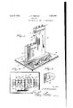
Figure 1 is a perspective view showing a type case constructed in accordance with my invention,
Figure 2 is a longitudinal sectional view taken on the line 22 of Figure 1 with one side wall removed, 7
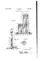
on the line Figure 3 is a vertical sectional view on the line 33 of Figure 2,
Figure 4: is a cross sectional view taken 4-4 of Figure 2 showing how the push plates operate to eject type, I
Figure 5 is a detail'perspective view showing the slots formed in the bottom of the removable side wall,
Figure 6 is a detail view showing one form of postmasters stamp having rubber type and used for stamping registered .matter and money orders, 7
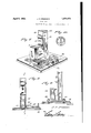
Figure 7 is a perspective view of amodified form of my invention designed to hold steel type, V
Figure 8 is a cross sectional view taken on the line 8-8 of Figure 7,
Figure9 is a cross sectional view taken on the line 9-9 of'Figure 8 with the removable side wall removed, and 1 70 Figure 10 is a detail view showing the postmasters canceling stamp using steel type.
Referring now to the drawings in which like characters oi reference designate simi lar parts in the various views the device is 75 shown to comprise a base 10 which is preferablyform'ed of aluminum and is substan tially rectangular in outline.
' Secured to the base is an upright case 11 also preferably formed of aluminum and comprising a side wall 12, end walls 13 and 14, and a side wall 15 which is removably secured to the end wall 14 by means of a screw 16 or otherwise. The side wall 15 forms a cover which when removed permits access to the interior of the case.
The case is provided with integral vertical division walls 17 which divide the interior of the case into compartments adapted to receive type in stacks. As illustrated the case is 90 higher at one end than at the other end so that in the present embodiment,,three tall compartments and three short compartments are formed. The purpose of this is to produce tall compartments for the type 18 bearing the dates of the month, thirty-one in all, while the short compartments may receive type 18' bearing the abbreviation of the name of the month, there being twelve of these.
Only two stacks of type are shownfor the purpose of illustration as these two stacks will be suliicient to supply the daily changes needed in stamps such as shown in Figure 6 and, used by postmasters for stamping registered matter and money orders. The remaining compartments being duplicates of those just described permit of three stamps belng supplied daily. It is to be understood that as many compartments may be built into the case as desired for supplying any number of stamps or for use in connection with type of various kinds used in offices, shipping rooms, etc.
The compartments above described are open at the bottom and the end wall l2 is provided between the .dividing walls 17 with a row of slots 19 through which type from :the various stacks may be selectively ejected by mechanism presently described. The removableside wall 15 is also provided with slots 20 which communicate with the tops of the compartments formed by the division walls and permit of used type being inserted into the case.
7 A pair of push plates 21 and 22 are sup ported on the base 10 and normally close the open bottoms of the compartments. Each push plate :is formed preferably square 1n outline and is p-rovided at the outer edge with an upturned grip 23 by means of which the plate maybe moved outwardly or inwardly. Each plate is provided with longitudinal slots 2-1 which receive the division walls .17, the latter vforming guides to direct the sliding movement of the push plates. It will be noted also by referring to Figure 5, that the removable wall 15 'is formed with projections '25 which also enter .the slots 24 and coact with the division walls 17 informing guides forthe push plates. The spaces between the projections 25 obviously constitute slots 26 which register with the slots 19 in the fixed wall 12 of the case and permit of the push plates being slid through both walls, of the case to eject type from the stacks as will presently be:described. V
For confining the push plates in position on the'base 10 a plate 27 is disposed above and houses the push plates. The plate 27 is "provided with dependinglugs 28 as shown in Figure 3, which enter slots 29 formed in the push platesand limit movement'of the push plates in either direction. The plate "27 is terminally provided'with lugs 30 which inter-fit with corresponding lugs 31 formedon the end walls of the case. Bolts 32 are passed through these. interfitting lugs and through thebase and'secure both the case and the push plates to the'base. Removal-of these two bolts permits easy disassembly of the parts.
Disposed in the top wall of the case is a plurality of plungers 33 which are slidably *fitted in the respectivecompartments formed by the division walls 17 and-press the corresponding stacks dcwnwardly so that the inatural stickiness inherent in rubber type will be overcome and the type urged downwardly to'dispose the lowermost type in position for ejection when the push plates are operated. A helical spring 34 is seated on the stem 35 of each plunger and presses against the top wall of the casing. The stem 35 of each plunger projects above the. casing and terminates in a knob 86 by means of which the plunger may be elevated against the tension of the spring 34, the knob being equipped with a collar 37 which engages the top of the case and limits downwardly movement of the plunger under the action of its spring. The plungers are normally held below the feed slots 20 above described and shown best in Figure l and must be raised by means of the knobs 36 when it is desired to replenish the stacks.
By now referring to Figure 4 it will be clear that the push plate 22 forms a bottom for the type compartments and supports the type. lVhen it is desired to eject type it is simply necessary to grasp the grip 23 and move the push :plat-e outwardly to the position occupied by the push plate 21 in Figure 1. The lowermost type of the stack will be forced downwardly by its respective plunger to occupy the space left by the withdrawn push plate, as shown by the numeral 18. To eject the type thepush plate is moved inwardly "to the position occupied by the push plate22, Figure 4, in which position of the parts the type indicated by the numeral 18 is ejected through the slots 19 in the fixed wall of the case. lilherever steel type is used such for instance as in the stamp shown in Figure 10 and used by postmasters for postmarlring letters, the :use of plungers above described may-be dispensed'withsince such type is comparatively large and heavy and will gravitate intoposition for being ejected from the :case. A modifiedform of the invention is accordingly shown in Figures 7, 8 and 9 in which :the parts are substantially similar to corresponding parts above described and hence :but a brief description will beentered into.
In the modified form the base 38 is preferably formed ofaluminum and rising from the base is :a case 39having a removable side wall 40 which is secured in 41.
place bya-screw The case 1s.substantially'the same in outline asthe preferred form above described with :the exception that the interior dimensions are greater to accommodate the steel type indicated at d2. The case is provided in teriorly with division walls 43 to divide :the
:case into compartments for holding the stacks of type. Three compartments are shown, a comparatlvely tall compartment .to .hold
thirty-one type carrying the dates :of' the month, and :two comparatively :short compartments adapted to hold twelve itype-each corresponding to the months of the year and twelve hours of the day. The compartments are supplied with type through slots 44: formed in the wall 40.
A plurality of push plates 45 are slidably mounted on the base 38 and are provided each with a longitudinal slot 46 which receives a stop lug 47 carried by a plate 48 which houses the push plates l5. The plate 48 and the case are both secured to the base 38 by spaced bolts 49. The plate 48 is provided with depending ribs 50 which form guides for the push plates so. The push plates are selectively operable as above described in detail to eject type 42 through slots 51 formed in the case.
In both the preferred form and also the modified form of the invention a hook 52 is secured to the case for the purpose of supporting a key, tweezers, or other similar tools.
From the above description it is thought hat the construction and operation of my invention will be clearly understood.
Having thus described the invention, I claim:
'1. A type case comprising a base, an upright casing on the base of greater height for a portion of its length than for the remaining portion of its length, division walls in the casing forming a short series of compartments and a tall series of compartments corresponding to the height of the walls of the casing for holding type in vertical stacks of different heights, there being a row of alined slots formed at the bottom of one wall of the casing between said division walls, there being a row of alined slots formed at the bottom of the opposite wall of said casing registering with the first named slots, fiat push plates slidable on said base through said registering slots in both walls of the casing for ejecting the lowermost type from the stacks, a cover plate removably secured to the base and extending over the ends of said push plates outside of the case, and grips on the outer ends of the push plates outside of the cover plate. I
2. A type case comprising a base, an upright casing thereon having vertical compartments for holding type in stacks, there being openings near the top of one side wall of the casing for supplying type to said compartments, spring-pressed plungers in the top of said casing extending below said openings for forcing said stacks downward in said compartments, stems on the plungers extending above the top of the casing for moving the plungers vertically above said openings to permit supplying type to the stacks, selectively operatable fiat push plates slidably mounted on said base for ejecting the lowermost type from said compartments, and a cover plate removably secured to the base and extending over the ends of said push plates outside of the case.
3. A type case comprising a base, an upright casing thereon for holding type in vertical stacks, division walls in the casing forming compartments for the different stacks, there being registering slots formed between the division walls in the side walls of the casing above said base, longitudinally slotted fiat push plates slidably mounted on said base and adapted to be shoved through said registering slots for ejecting the lowermost type rearwardly from the stacks, projections on the bottom edges of the division walls extending into certain of the slots of the push plates for directing sliding movement of the push plates, a cover plate on said base housing the exposed ends of said push plates, and stops carried by said cover plate and projecting into one of the slots of each of said push plates for limiting movement of said push plates.
l. A type case comprising a base, an up right casing thereon for holding type in vertical stacks, selectively operatable flat push plates slidably mounted on said base for expelling the lowermost type from the stacks,
a cover plate on the base housing the outer exposed ends of said push plates and having division walls extending between and forming guides for the push plates, said push plates being slotted longitudinally, stops projecting downwardly from said cover plate into the longitudinal slots of the push plates and coacting with the end walls thereof to limit movement of said push plates, and means for removably securing the cover plate to the base.
In testimony whereof I affix my signature.
JAMES PERCY FREEMAN-
Priority Applications (1)
| Application Number | Priority Date | Filing Date | Title |
|---|---|---|---|
| US435310A US1851979A (en) | 1930-03-12 | 1930-03-12 | Type case |
Applications Claiming Priority (1)
| Application Number | Priority Date | Filing Date | Title |
|---|---|---|---|
| US435310A US1851979A (en) | 1930-03-12 | 1930-03-12 | Type case |
Publications (1)
| Publication Number | Publication Date |
|---|---|
| US1851979A true US1851979A (en) | 1932-04-05 |
Family
ID=23727872
Family Applications (1)
| Application Number | Title | Priority Date | Filing Date |
|---|---|---|---|
| US435310A Expired - Lifetime US1851979A (en) | 1930-03-12 | 1930-03-12 | Type case |
Country Status (1)
| Country | Link |
|---|---|
| US (1) | US1851979A (en) |
-
1930
- 1930-03-12 US US435310A patent/US1851979A/en not_active Expired - Lifetime
Similar Documents
| Publication | Publication Date | Title |
|---|---|---|
| US2291187A (en) | Match box dispenser | |
| US1851979A (en) | Type case | |
| US869614A (en) | Accounting device. | |
| US2246431A (en) | Chip dispenser | |
| US1987914A (en) | Dispensing machine | |
| US3122095A (en) | Laminated make-up printing stamp | |
| US1061883A (en) | Card-punching machine. | |
| US483849A (en) | Advertising or business cabinet | |
| US201718A (en) | Improvement in type-holders | |
| US1101535A (en) | Date-holder. | |
| US2470884A (en) | Distribution board | |
| US1269979A (en) | Dating and mutilating machine. | |
| US2588286A (en) | Card index | |
| US1038742A (en) | Rubber-stamp cabinet. | |
| US2037192A (en) | Visible inventory and sales recording device | |
| USRE16718E (en) | Sylvania | |
| US1035001A (en) | Account-register. | |
| CH448137A (en) | Sheet dispenser | |
| US1212314A (en) | Stamp-affixer cabinet. | |
| US1151501A (en) | Printing-plane. | |
| US825726A (en) | Individual-check distributer. | |
| US891624A (en) | Ticket printing and registering apparatus. | |
| US2049438A (en) | Device for inserting index tabs | |
| US1029568A (en) | Hand-stamp. | |
| US996610A (en) | Vending device. |