US1851884A - Device for cambering spring leaves - Google Patents
Device for cambering spring leaves Download PDFInfo
- Publication number
- US1851884A US1851884A US418618A US41861830A US1851884A US 1851884 A US1851884 A US 1851884A US 418618 A US418618 A US 418618A US 41861830 A US41861830 A US 41861830A US 1851884 A US1851884 A US 1851884A
- Authority
- US
- United States
- Prior art keywords
- cambering
- elements
- spring leaves
- leaves
- links
- Prior art date
- Legal status (The legal status is an assumption and is not a legal conclusion. Google has not performed a legal analysis and makes no representation as to the accuracy of the status listed.)
- Expired - Lifetime
Links
- RTZKZFJDLAIYFH-UHFFFAOYSA-N Diethyl ether Chemical compound CCOCC RTZKZFJDLAIYFH-UHFFFAOYSA-N 0.000 description 2
- 238000004519 manufacturing process Methods 0.000 description 2
- 101000983594 Bos taurus Caspase-13 Proteins 0.000 description 1
- 238000005452 bending Methods 0.000 description 1
Images
Classifications
-
- B—PERFORMING OPERATIONS; TRANSPORTING
- B21—MECHANICAL METAL-WORKING WITHOUT ESSENTIALLY REMOVING MATERIAL; PUNCHING METAL
- B21D—WORKING OR PROCESSING OF SHEET METAL OR METAL TUBES, RODS OR PROFILES WITHOUT ESSENTIALLY REMOVING MATERIAL; PUNCHING METAL
- B21D53/00—Making other particular articles
- B21D53/88—Making other particular articles other parts for vehicles, e.g. cowlings, mudguards
- B21D53/886—Making other particular articles other parts for vehicles, e.g. cowlings, mudguards leaf springs
Definitions
- This invention relates to a device for cambering spring leaves which is provided with suitable adjusting means for varying at will the radius of curvature within Wide 5 limits.
- Figure 1 is a partial front view of the ⁇ device.
Landscapes
- Engineering & Computer Science (AREA)
- Mechanical Engineering (AREA)
- Springs (AREA)
Description
March 29, 1932. T-. ZERBI DEVICE FOR CAMBERING SPRING LEAVES Filed Jan. 4, @93o Flg. 1
fla
n i nu ...1.
. laam. mi A, W f..
.III
Patented Mar. 29, 1932 UNT STATES PATENT OFFICE TBANQUILLO .ZERBL OF TURIN, ITALY, ASSIGNOR TO FIAT SOCIET ANONIMA., OF
TURIN, ITALY l DEVICE FOR `OAMI?,ERICE'Gr SPRING LEAVES Application led January 4, 1930, Serial No.f418,618, and in Italy` November 29, 1929.
This invention relates to a device for cambering spring leaves which is provided with suitable adjusting means for varying at will the radius of curvature within Wide 5 limits.
The characteristic feature of the device consists in the fact that the two pressing surfaces for cambering the spring leaf instead of being continuousare formed by a plurality of small successive surfaces pertaining Vto two superposed rows of elements connected p to one another in the manner of chain links and provided with members for varying at will the relative position of each element with respect to those between which it is comprised in the chain, so that the chamber can be varied within wide limits.
Both chains are carried in an adjustable manner by supporting blocks mounted in the usual cambering machine.
The accompanying drawings show by way of example a constructional form of the device limited to less than one-half of the whole arrangement for clearness sake.
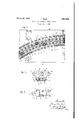
Figure 1 is a partial front view of the` device.
Figures 2 and 3 show on an enlarged scale infront and plan view respectively two successive elements of one of the rows of the device.
The device comprises two rows of elements A and B, each of which is formed by a body 1 provided with two projecting bearing surfaces 2 and 3 contacting the faces of the leaf 4 to be cambered. Each elementl carries on one side a sleeve 5 and on the opposite side two flanges 6 and 6 conveniently spaced to permit the sleeve 5 of the adjacent element to engage between them. On the side opposite to the bearing surfaces 2 and 3 the elements 1 carry two parallel projecting arms 8 and 8 conveniently spaced from each other. In the holes 9, 10, respectively, of the sleeve 5 and corresponding flangesl 6, 6 are passed the pivots 7 connecting the chain elements. On the ends of the arms 8, 8 are bored coaxial holes 11 through which are passed the pivots 12, on vwhich are mounted the heads 13 of screw-threaded spindles 14 on which are screwed the nuts 15 with onehalf right-handed and one-half left-handed screw-thread for drawing together or removing from each other the corresponding spindles 14 which have alternatively opposite screw-threads corresponding to those of the nuts 15.
The elements 1 have a central bore 16 serving for the oil inlet and circulation in the following hardening operation as well as for litting in bolts 17 for securing the two superosed rows of pressing elements to the plates 18 and 19 of the press. The said bolts 17 are passed in slits 20 correspondingly cut in both plates 18 and 19.
It is obvious that by screwing more or less tightly the nuts 15 of the upper row A and those of the lower row B a very large number of different cambers for the leaves 4 of the spring can be obtained. By providing a plurality of chains A and B of elements 1 of different size it is possible to extend the use of the machine provided with the universal pressing arrangement in order to obtain pressed leaves of any shape with an easy and quick fitting of the press either for making samples or a commercial production with the advantager that the leaves made on a commercial scale shall have the same features as the models chosen for the regular production after practical tests.
The shape of the elements of the two superposed rows according to this application may vary from that shown in the example illustrated without departing from the spirit of this invention.
What I claim is:
1. A mandrel for arcuately bending leaf members, said mandrel comprising arcuately disposed flexible members, said flexible membersbeing formed from links, the ends of said links beingl hingedly connected to ether, article engaging heads carried kby sai links of each flexible member and extending towards each other, said links having their n turn buckles forming means whereby the links l may be adjusted in various arcs. j
soV
2. In a device for cambering spring leaves, the combination with dies formed by a succession of cross shaped elements, said elements being hingedly connected together and provided with central transverse apertures and a support for said dies, of attachment pla-tes connecting said dies to the support, bolts passing through said apertures and through slots on said support and tensioning .devices rigidly connecting the arms of the cross shaped elements at points remote iny relation to a pressing surface.
In testimony that I claim the foregoing as my invention, I have signed my name.
ING. TRANQUILLO ZERBI.
Applications Claiming Priority (1)
| Application Number | Priority Date | Filing Date | Title |
|---|---|---|---|
| IT1851884X | 1929-11-29 |
Publications (1)
| Publication Number | Publication Date |
|---|---|
| US1851884A true US1851884A (en) | 1932-03-29 |
Family
ID=11434742
Family Applications (1)
| Application Number | Title | Priority Date | Filing Date |
|---|---|---|---|
| US418618A Expired - Lifetime US1851884A (en) | 1929-11-29 | 1930-01-04 | Device for cambering spring leaves |
Country Status (1)
| Country | Link |
|---|---|
| US (1) | US1851884A (en) |
Cited By (1)
| Publication number | Priority date | Publication date | Assignee | Title |
|---|---|---|---|---|
| US2868264A (en) * | 1954-10-22 | 1959-01-13 | Fairchild Engine & Airplane | Articulated die |
-
1930
- 1930-01-04 US US418618A patent/US1851884A/en not_active Expired - Lifetime
Cited By (1)
| Publication number | Priority date | Publication date | Assignee | Title |
|---|---|---|---|---|
| US2868264A (en) * | 1954-10-22 | 1959-01-13 | Fairchild Engine & Airplane | Articulated die |
Similar Documents
| Publication | Publication Date | Title |
|---|---|---|
| US2280359A (en) | Sheet metal forming apparatus | |
| US1851884A (en) | Device for cambering spring leaves | |
| US2343947A (en) | Wing nut | |
| US1849054A (en) | Apparatus for the manufacture of metal tubes | |
| US1536886A (en) | Antiskid device | |
| DE578727C (en) | Connector sleeve for electrical plug contacts | |
| US1444481A (en) | Device for regulating the adjustment of tools on machine tools | |
| US1346507A (en) | Method of making chains | |
| US2175156A (en) | Crankshaft | |
| DE2720014C2 (en) | ||
| DE536935C (en) | Power transmission chain | |
| US1493256A (en) | Flexible driving shaft | |
| DE125544C (en) | ||
| US2222381A (en) | Hinged belt coupler | |
| DE522626C (en) | Device for bending spring leaves between articulated chains | |
| US2914842A (en) | Method of making a heat exchanger | |
| DE534388C (en) | Device for corrugating square tubes for partial chamber boilers | |
| DE525995C (en) | Egg sorter | |
| US1589798A (en) | Wire crimper | |
| DE701824C (en) | Device for winding a wire screw into a pack of sheets of paper perforated parallel to its back | |
| DE648755C (en) | Metal intermediate element for anti-skid devices on vehicle tires | |
| DE505563C (en) | Saddle for bicycles, motorcycles and similar vehicles | |
| US1856686A (en) | Metal lath expander | |
| DE17353C (en) | Wick moving device for double flat burners on lamps | |
| US1447769A (en) | Press |