US1851741A - Building structure - Google Patents
Building structure Download PDFInfo
- Publication number
- US1851741A US1851741A US415521A US41552129A US1851741A US 1851741 A US1851741 A US 1851741A US 415521 A US415521 A US 415521A US 41552129 A US41552129 A US 41552129A US 1851741 A US1851741 A US 1851741A
- Authority
- US
- United States
- Prior art keywords
- boards
- plaster
- clips
- building structure
- abutting
- Prior art date
- Legal status (The legal status is an assumption and is not a legal conclusion. Google has not performed a legal analysis and makes no representation as to the accuracy of the status listed.)
- Expired - Lifetime
Links
- 239000011505 plaster Substances 0.000 description 23
- 238000010276 construction Methods 0.000 description 6
- 238000009408 flooring Methods 0.000 description 3
- 239000002184 metal Substances 0.000 description 3
- 238000009435 building construction Methods 0.000 description 2
- 241000508724 Conorete Species 0.000 description 1
- 230000015572 biosynthetic process Effects 0.000 description 1
- 230000008878 coupling Effects 0.000 description 1
- 238000010168 coupling process Methods 0.000 description 1
- 238000005859 coupling reaction Methods 0.000 description 1
- 239000000463 material Substances 0.000 description 1
- 239000000203 mixture Substances 0.000 description 1
- 230000008520 organization Effects 0.000 description 1
- 230000002787 reinforcement Effects 0.000 description 1
Images
Classifications
-
- E—FIXED CONSTRUCTIONS
- E04—BUILDING
- E04B—GENERAL BUILDING CONSTRUCTIONS; WALLS, e.g. PARTITIONS; ROOFS; FLOORS; CEILINGS; INSULATION OR OTHER PROTECTION OF BUILDINGS
- E04B9/00—Ceilings; Construction of ceilings, e.g. false ceilings; Ceiling construction with regard to insulation
- E04B9/22—Connection of slabs, panels, sheets or the like to the supporting construction
Definitions
- the present invention has relation to a building construction and has more particular relation to formation of a ceiling of precast slabs.
- One object of the present invention is to provide a novel construction of parts which may be assembled by unskilled labor in an eflicient manner to provide a comparatively inexpensive structure.
- a further object is to provide a plaster board ceiling construction which in assembled condition is relatively rigid throughout its longitudinal extent.
- a still further object of the present invention resides in a novel mode of plaster board ceiling attachment.
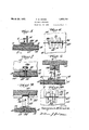
- Fig. 2 is a view in plan, of the plaster boards shown in Fig. 1, with the flooring and I-beams omitted.
- Fig. 3 is a fragmentary sectional view hereinafter referred to.
- Fig. 4 is a view in elevation of a tie bar hereinafter referred to.
- Fig. 5 is a fragmentary view in section, hereinafter referred to.
- Fig. 6 is a sectional view taken on the line 6-6 of Fig. 5.
- V Fig. 7 is a view in section taken on the line 7-7 of Fig. 5.
- Fig. 8 is a fragmentary view in section of a modified form of construction.
- Fig. 9 is a view in section taken upon the line 9--9 of Fig. 8.
- Fig. 1() is a section on line lO-l() of Fig. 8.
- the reference numeral 101 designa-tesa flooring which may be concrete or other fireprooflng material. Extended throughout the length of the floor is a reinforcement 11. Depending from the flooring 10 and embedded therein are spaced I-beams 12 from which I sus 7 pend my novel form of plaster board, a description of which follows. 13 designates a plaster composition having a covering of paper 14. These plaster boards are rectangular in shape and arel ⁇ arranged end to end in abutting relation, and are secured or eoupled togetherv by' means of metal clips 21 which marginally engage the plaster boards.
- a backing strap 22' is provided which parallels the plaster boards and is arranged so as to seat between the prongs of the clips 21'. It sometimes happens that the'v plaster boards sag adjacent their meeting edges and to assist in preventing this I make use of tie rods best seen in Figs. 3 and 4.
- the prongs 15 are extended downwardly through the apertures 16 in the plaster boards and the free ends tww'sted together beneath adjacent plaster boards, as clearly shown in Fig.v 3, it being understood Vthat a coat of plaster 18, see Fig. l, covers the under surfaces of the plaster boards, thus concealing the twisted endsof the prongs ofthe tie rods. Thus, general rigidity of plaster boards is provided.
- the clips 21 are shaped upon an angle so as to wedge over the tops of the lower rails of the I-beams 12 and secure the plaster boards 13, clips 21, and clips 30 in an efficient coupling which may be attached by unskilled labor.
- the floor 10 of concrete or the like has embedded therein a twisted wire having a loop 31 depending from which is a strap 32 secured with respect to the loop 31 by means of a conventional wire nail 33.
- a strap 32 secured with respect to the loop 31 by means of a conventional wire nail 33.
- Bolted at 36 to the strap 32 is an L- shaped member 34 the lower end of which supports the clips 35 which are similar in all respects to the clips 21, seen in Figs. 5, 6, and 7.
- a floor of conorete or the like spaced I-beams depending from said floor, a series of abutting plaster boards to form a ceiling, said boards being apertured adjacent their ends and arranged with their end edges abutting, clips for engaging around the meeting marginal edges of said abutting boards to maintain the same in alignment, and an auxiliary clip for engaging over the lower rail of an I-beam to suspend said boards, and means passing through said apertures for tying said boards together.
- a floor of concrete or the like spaced I-beams depending from said floor, aseries of abutting plaster boards to form a ceiling, said boards being apertured and arranged with their edges abutting, clips for engaging around the meeting marginal edges of said abutting boards to maintain the same in alignment, an auxiliary 4 clip for engaging over the lower rail of an I- beam to suspend said boards, and metaltie rods extended through the apertures of said plaster boards to a position therebeneath and twisted together to provide plaster board Stability.
- a floor of concrete or the like spaced I-beams depending from said floor, a series of abutting plaster boards to form a ceiling, said boards being apertured and arranged with their edges abutting, clips for engaging around the meeting marginal edges of said abutting boards to maintain the same in alignment, an auX- iliary clip for engaging over the lower rail of an I-beam to suspend said boards, metal tie rods extended through the apertures of said plaster boards to a position therebeneath and twisted together to provide plaster board stability, and spaced vertically arranged boards.
Landscapes
- Engineering & Computer Science (AREA)
- Architecture (AREA)
- Physics & Mathematics (AREA)
- Electromagnetism (AREA)
- Civil Engineering (AREA)
- Structural Engineering (AREA)
- Building Environments (AREA)
- Finishing Walls (AREA)
Description
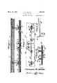
' March '29, 1932. F. M. vr-:NznF
` BUILDING STRUCTURE Filed Deo. 20,l 1929 2 sheets-Sheet l I NV EN TOR.
@Mgg
March 29, 1932. F M, VENZ|E 1,851,741
BUILDING STRUCTURE Filed Deo. 20 1929 2 Sheets-Sheet 2 INVENTOR.
l5, FFEDE/P/c/MIA/z/E. "521 BY Patented Mar. 29, 1932? PATENT OFFICE FREDERICK M. VENZIE,. F `IPIEIIIJADELEHIA, PENNSYLVANIA BUILDING STRUCTURE Application filed December 20,1929. Serial No. 415,521.
The present invention has relation to a building construction and has more particular relation to formation of a ceiling of precast slabs.
One object of the present invention is to provide a novel construction of parts which may be assembled by unskilled labor in an eflicient manner to provide a comparatively inexpensive structure.
A further object is to provide a plaster board ceiling construction which in assembled condition is relatively rigid throughout its longitudinal extent.
A still further object of the present invention resides in a novel mode of plaster board ceiling attachment.
Other and further objects of the present invention resides in the provision of general details of construction and arrangement of parts of attaining the results sought by the said leading objects.
With these and other objects in view, the invention consists of the novel construction hereinafter described and finally claimed.
The nature, characteristic features and scope of the invention will be more fully understood from the following description taken in connection with the accompanying drawings, forming part hereof, and in which z Fig. l is a view in longitudinal section of a building structure embracing my novel invention.
Fig. 2 is a view in plan, of the plaster boards shown in Fig. 1, with the flooring and I-beams omitted.
Fig. 3 is a fragmentary sectional view hereinafter referred to.
Fig. 4 is a view in elevation of a tie bar hereinafter referred to.
Fig. 5 is a fragmentary view in section, hereinafter referred to.
Fig. 6 is a sectional view taken on the line 6-6 of Fig. 5.
V Fig. 7 is a view in section taken on the line 7-7 of Fig. 5.
Fig. 8 is a fragmentary view in section of a modified form of construction.
Fig. 9 is a view in section taken upon the line 9--9 of Fig. 8.
Fig. 1() is a section on line lO-l() of Fig. 8.
For the' purpose of illustrating m-y invention I have shown. in the accompanying drawings two forms thereof which are at present preferred by me, since the same has been found in practice to give satisfactory and reliable results, although it is to be understood that the various instrumentalities of which my invention consist-s can be variously arranged and organized and that my invention is not limited to the precise arrangement and organization of the instrumentalities as herein shown and described.
Referring now to the drawings in detail, and with more especial relation to Fig. 1, the reference numeral 101 designa-tesa flooring which may be concrete or other fireprooflng material. Extended throughout the length of the floor is a reinforcement 11. Depending from the flooring 10 and embedded therein are spaced I-beams 12 from which I sus 7 pend my novel form of plaster board, a description of which follows. 13 designates a plaster composition having a covering of paper 14. These plaster boards are rectangular in shape and arel `arranged end to end in abutting relation, and are secured or eoupled togetherv by' means of metal clips 21 which marginally engage the plaster boards. In order to provide relative rigidity, a backing strap 22' is provided which parallels the plaster boards and is arranged so as to seat between the prongs of the clips 21'.. It sometimes happens that the'v plaster boards sag adjacent their meeting edges and to assist in preventing this I make use of tie rods best seen in Figs. 3 and 4. Upon the plaster board tops I arrange parallel Cross-piece 17 0f metal, serving as stiileners, and fit thereover the hooked ends 37 kof members 25 with which prongs l5 have swivel relation at 24. The prongs 15 are extended downwardly through the apertures 16 in the plaster boards and the free ends tww'sted together beneath adjacent plaster boards, as clearly shown in Fig.v 3, it being understood Vthat a coat of plaster 18, see Fig. l, covers the under surfaces of the plaster boards, thus concealing the twisted endsof the prongs ofthe tie rods. Thus, general rigidity of plaster boards is provided.
To the bottom rails of the I-beams 12 I attach the clips 21 by means of the clip 30, see Figs. 5 and 7. The clips 30 are shaped upon an angle so as to wedge over the tops of the lower rails of the I-beams 12 and secure the plaster boards 13, clips 21, and clips 30 in an efficient coupling which may be attached by unskilled labor.
Taking up now'the modified Jform oi attachment shown in Figs. 8, 9, and 10, the floor 10 of concrete or the like has embedded therein a twisted wire having a loop 31 depending from which is a strap 32 secured with respect to the loop 31 by means of a conventional wire nail 33. Bolted at 36 to the strap 32 is an L- shaped member 34 the lower end of which supports the clips 35 which are similar in all respects to the clips 21, seen in Figs. 5, 6, and 7.
By the above described arrangement and construction of ceiling' parts, a very eilicient, relatively inexpensive lay-out may be effected by unskilled labor, thus materially reducing the cost of building construction.
What I claim is:
l. In a building structure a floor of conorete or the like, spaced I-beams depending from said floor, a series of abutting plaster boards to form a ceiling, said boards being apertured adjacent their ends and arranged with their end edges abutting, clips for engaging around the meeting marginal edges of said abutting boards to maintain the same in alignment, and an auxiliary clip for engaging over the lower rail of an I-beam to suspend said boards, and means passing through said apertures for tying said boards together.
2. In a building structure, a floor of concrete or the like, spaced I-beams depending from said floor, aseries of abutting plaster boards to form a ceiling, said boards being apertured and arranged with their edges abutting, clips for engaging around the meeting marginal edges of said abutting boards to maintain the same in alignment, an auxiliary 4 clip for engaging over the lower rail of an I- beam to suspend said boards, and metaltie rods extended through the apertures of said plaster boards to a position therebeneath and twisted together to provide plaster board Stability.
3. In a. building structure, a floor of concrete or the like, spaced I-beams depending from said floor, a series of abutting plaster boards to form a ceiling, said boards being apertured and arranged with their edges abutting, clips for engaging around the meeting marginal edges of said abutting boards to maintain the same in alignment, an auX- iliary clip for engaging over the lower rail of an I-beam to suspend said boards, metal tie rods extended through the apertures of said plaster boards to a position therebeneath and twisted together to provide plaster board stability, and spaced vertically arranged boards.
FREDERICK M. VENZIE.
Priority Applications (1)
| Application Number | Priority Date | Filing Date | Title |
|---|---|---|---|
| US415521A US1851741A (en) | 1929-12-20 | 1929-12-20 | Building structure |
Applications Claiming Priority (1)
| Application Number | Priority Date | Filing Date | Title |
|---|---|---|---|
| US415521A US1851741A (en) | 1929-12-20 | 1929-12-20 | Building structure |
Publications (1)
| Publication Number | Publication Date |
|---|---|
| US1851741A true US1851741A (en) | 1932-03-29 |
Family
ID=23646027
Family Applications (1)
| Application Number | Title | Priority Date | Filing Date |
|---|---|---|---|
| US415521A Expired - Lifetime US1851741A (en) | 1929-12-20 | 1929-12-20 | Building structure |
Country Status (1)
| Country | Link |
|---|---|
| US (1) | US1851741A (en) |
-
1929
- 1929-12-20 US US415521A patent/US1851741A/en not_active Expired - Lifetime
Similar Documents
| Publication | Publication Date | Title |
|---|---|---|
| US1615096A (en) | Floor and ceiling construction | |
| US1804132A (en) | Construction unit | |
| US1596284A (en) | malmgren | |
| US320567A (en) | Tile setting | |
| US2268311A (en) | Concrete floor construction | |
| US2271584A (en) | Wall construction | |
| US1851741A (en) | Building structure | |
| US1779713A (en) | Building construction | |
| US1724284A (en) | Building construction | |
| US1831162A (en) | Furred wall and ceiling structure | |
| US1807315A (en) | Concrete form for floors | |
| US2313325A (en) | Floating wall construction | |
| US1693949A (en) | Support for nailing strips and the like | |
| US1862728A (en) | Building structure | |
| US679430A (en) | Floor and ceiling construction. | |
| US830494A (en) | Building construction. | |
| US1798380A (en) | Roof construction | |
| GB481984A (en) | Improvements in floor construction | |
| US1791639A (en) | Correlating means for ceiling or partition panels | |
| US1478277A (en) | Stair platform and landing | |
| US1885496A (en) | Building construction | |
| US719892A (en) | Fireproof floor and ceiling construction. | |
| US1842348A (en) | Building wall construction | |
| US598481A (en) | William orr | |
| US983699A (en) | Concrete structure. |