US1851645A - Visible index - Google Patents
Visible index Download PDFInfo
- Publication number
- US1851645A US1851645A US37627A US3762725A US1851645A US 1851645 A US1851645 A US 1851645A US 37627 A US37627 A US 37627A US 3762725 A US3762725 A US 3762725A US 1851645 A US1851645 A US 1851645A
- Authority
- US
- United States
- Prior art keywords
- card
- hanger
- index
- hinge
- hinges
- Prior art date
- Legal status (The legal status is an assumption and is not a legal conclusion. Google has not performed a legal analysis and makes no representation as to the accuracy of the status listed.)
- Expired - Lifetime
Links
- 239000011324 bead Substances 0.000 description 7
- 238000010276 construction Methods 0.000 description 5
- 230000009975 flexible effect Effects 0.000 description 3
- 239000002184 metal Substances 0.000 description 3
- BSYNRYMUTXBXSQ-UHFFFAOYSA-N Aspirin Chemical compound CC(=O)OC1=CC=CC=C1C(O)=O BSYNRYMUTXBXSQ-UHFFFAOYSA-N 0.000 description 1
- 208000025814 Inflammatory myopathy with abundant macrophages Diseases 0.000 description 1
- 244000057196 artichoke thistle Species 0.000 description 1
- 229940000425 combination drug Drugs 0.000 description 1
- 238000003780 insertion Methods 0.000 description 1
- 230000037431 insertion Effects 0.000 description 1
- 239000000463 material Substances 0.000 description 1
- 238000000034 method Methods 0.000 description 1
Images
Classifications
-
- B—PERFORMING OPERATIONS; TRANSPORTING
- B42—BOOKBINDING; ALBUMS; FILES; SPECIAL PRINTED MATTER
- B42F—SHEETS TEMPORARILY ATTACHED TOGETHER; FILING APPLIANCES; FILE CARDS; INDEXING
- B42F17/00—Card-filing arrangements, e.g. card indexes or catalogues or filing cabinets
- B42F17/18—Card-filing arrangements, e.g. card indexes or catalogues or filing cabinets in which the cards are stored in a flat position
Definitions
- This invention relates to visible indexes, and refers more particularly to visible index cards ⁇ mounted in overlapping relation on a L frame.
- Y "g1 V The specific embodiment of the present 1nvention resides in having the cards removably attached to hinges7 which latter may themselves constitute hangers, or which may (q be auxiliary to and removably mounted on 10 they hangers.
- Thehinge element of the present invention is provided with means whereby the cards are supported on or adJacent their side edges.
- Each hinge element per se (M takes the form of two opposite side card supporting plates provided with card holding means and connected by means of a substantially rigid connecting piece. In other words, the connecting link between each pair of side M plates is constructed of non-iiexible metal.
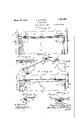
- Fig. 1 is a face view of a visible index construction in normal position, to which my invention is applied.
- Fig. ⁇ 2 is a cross-sectional view taken on lines 2-2 of Fig. 1. y g
- Fig. 3 is a perspective' view of the hinge M element.
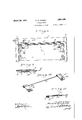
- "'30 Fig. 4 is a fragmentary face view of one upper corner of an index card provided with a notch to engage the hinge.
- Fig.,5 is a view similar to Fig. 1 illustrating Fig. is a perspective view of the hinge element shown in Fig. 9.
- Fig.,11 is a cross-sectional view taken on Referring now 'more particularly to Figs.
- 1 designates the central web
- 2 the flanged or channelledl side guides of a metal frame of standard construction now in extensive use.
- the flexible hanger 3 may vtake theV form of resilient lengths of wire extending across the central web 1 of the frame and having spaced returnbent ends upon which the hinge elements des! ignated as a whole 1 are placed.
- the hinge elements may comprise two substantially flat metal plates 5 and 5a connected by means of connecting rod 6 which in the present instance is constructed of a substantlally non-flexible material.
- connecting rod 6 On opposite outer edges of each pair of plates 5 is a spaced return-bent lip 7 forming the means for locking the cards in place.
- each plate 5 may be bent at one end to form a bead 8 and each plate 5a may be bent at one endrto form a bead 8a provided with a longitudinall opening 8,.
- a second closed bead 9 may also be formed adjacent the beads 8 and 8a.
- the outer bent end of the plate 5b may be closed and may be permanently attached to the rod 6 whereas the intermediate bead 10 may be open and mzy be adapted to snap 'over the ends of the ro 3.
- one plate 5 may be threaded upon one hanger 3.
- the opposite plate atmay be snapped on to the opposite hanger 3 in a manner similar to the mounting of the plate 5a upon the hanger 3 in the mo'diiicationshown in Fig. 1. f
- Index cards 11 may be provided' with notches 12 on their upper side edges, said ⁇ Vcards being readily mountable on or removable'from each hinge elementby being bent centrally, the cards of course7 being iexible enough to permit this being done.
- hinges having pintle eyesniayfbe attached von the upper edge of the cards. ⁇ These hinges are more or less permanently attached to the cards, which is of course, very desirable in certain instances. However, at other times, it has been found necessary to remove the card from the hinge, for instance, to allow the card to be rolled around the platen of a typewriter.
- the present invention was perfected to facilitate the removal of cards from hinges, and the arrangement described herein, accomplishes this purposev v ery readily.
- the cards are instantly mountable onfor removable from, theihinge element without disturbing in any way the position of the hinge.
- Y Y l Y I have shown one cardand hinge element in Figs. 1 and 5. It is understood ofcourse, that the cards -are mounted/in overlapping relation, ,spaced by the return-bent ends of the hangers. Y
- the index cards 11 instead of being provided on, their upper side edges with notches such as.Y shown at 12 in Ficht may be provided with the internal y notches 13, which notches take the form of ay slightly enlarged' circular opening 14y and an elongated narrow slot 15 extendingI inwardly from the opening 14.
- the plates 5 instead of being provided with locking lips 7., as are the plates 5, 5a and 5b may be provided with the locking lips 16, the construction of which is clearly shown in Fig. 11.
- the rod 6 connectingtheplates 5 is made of Vflexiblematerial instead'of being rigid as in the first form, and to mount the hinges upon the hanger 3, one plate 5"1nay be mounted upon one end of thehanger, the rod 6 connecting the two plates 5 maythen be flexedto permit the insertion of the opposite plate 5 upon theopposite end of the hanger ⁇ I" claim as my invention:
- A'visible index comprising in 'combina tion a supporting frame having side lianges, an index card, means for detachably supporting said index card on said frame, comprising a hanger adaptedto have engagement with saidv frame in;y said side flanges, card'- supporting elements adapted'to have engagenient,A with said hanger, ⁇ V comprising spaced hinge elements, and means wherebysaid in dex cardmay be mounted on or removed'from said ⁇ hinges Vwithout disturbing the position ofi the hinges relative tothe hanger.
- vAvvisible index comprising in combiflanges, card-supporting means adapted to have detachable engagement with. hanger, comprising spaced hinge elements, and
- index cardy may be mounted on ori removed VVfronrsad hinges without disturbing theposition of the hinges relative to the hanger.
- a visible index comprising in combii .nation a supporting frame having side flanges, an index card, means for detachably supporting, said index card 'on said frame,
- a hanger adaptedfto have detach able engagement withlsaid' frameinfsaid side flanges
- card-supporting means adaptedto have detachable engagementwithsaidhanger, comprisingspaced hinge elements, and means whereby said indexVv card may be vmounted .on or removed fromi said hinges without disturbing the. position offthehinges relative tothe hanger.
- indexxcard supporting means adapted to have. detachable cooper-4 ative engagement with therreturnz-bentends of the hanger, comprising spacedhingesconf nected into a unitary structurefbyanon-flex.- ible" connecting strip,L and.. an .indexn card adapted to be hinges.
- a supporting frame having side flanges, an index card, meansifor detachably supporting saidy index card, onsaid. frame, fj
- a visible index comprising incombination Ya supporting frame, an! indexj car'd, means for detachably supporting saidfcard las relative to said frame, comprising a resilient support vadapted toy cooperativelyff'engage said frame, card-supporting mean'siadapted to have engagement with said resilient s upport comprising spaced' hinge'elements, and
- index? cardV may' 'be mounted/on or removedfronrsaid-hinge elements without disturbingfthe position ofitle hinge elements r'elativet'ofthehangeri4 7.
- lA visible index comprisingiihcombiina- FRANK D. ⁇ POWELL.
Landscapes
- Extensible Doors And Revolving Doors (AREA)
Description
March 29, 1932. F. D. POWELL `1,851,645.
' VISIBLE INDEX Zz/n 656.' 1 771/671250 7d:
Mardi 29, 1932.
F. D. POWELL VISIBLE INDEX Filed June 17, 1925 2 Sheets-Sheet 2 Patented Mar. 29, 1932 imam: nrowELL, oF CHICAGO, ILLINOIS,
NT OFFICE ASSIGNAOR TO ACME CARD SYSTEM COlVIf .'PANY, OF CHICAGO, ILLINOIS, A CORPORATION OF ILLINOIS VISIBLE INDEX This invention relates to visible indexes, and refers more particularly to visible index cards `mounted in overlapping relation on a L frame. Y "g1 VThe specific embodiment of the present 1nvention resides in having the cards removably attached to hinges7 which latter may themselves constitute hangers, or which may (q be auxiliary to and removably mounted on 10 they hangers. Thehinge element of the present invention is provided with means whereby the cards are supported on or adJacent their side edges. Each hinge element per se (M, takes the form of two opposite side card supporting plates provided with card holding means and connected by means of a substantially rigid connecting piece. In other words, the connecting link between each pair of side M plates is constructed of non-iiexible metal.
Various advantages and objects of the present invention will be brought out more particularly in the following description:
In the drawings, Fig. 1 is a face view of a visible index construction in normal position, to which my invention is applied.
Fig.`2 is a cross-sectional view taken on lines 2-2 of Fig. 1. y g
Fig. 3 ,is a perspective' view of the hinge M element. "'30 Fig. 4 is a fragmentary face view of one upper corner of an index card provided with a notch to engage the hinge.
,Fig.,5 is a view similar to Fig. 1 illustrating Fig. is a perspective view of the hinge element shown in Fig. 9.
Fig.,11 is a cross-sectional view taken on Referring now 'more particularly to Figs.
a slightly modified method of uniting thev 5 side plates to the rigid connecting piece.
Application filed .Tune 17, 1925. Serial No. 37,627.`
1 to 7 of the drawings, 1 designates the central web, and 2 the flanged or channelledl side guides of a metal frame of standard construction now in extensive use. The flexible hanger 3 may vtake theV form of resilient lengths of wire extending across the central web 1 of the frame and having spaced returnbent ends upon which the hinge elements des! ignated as a whole 1 are placed.`
The hinge elements may comprise two substantially flat metal plates 5 and 5a connected by means of connecting rod 6 which in the present instance is constructed of a substantlally non-flexible material. On opposite outer edges of each pair of plates 5 is a spaced return-bent lip 7 forming the means for locking the cards in place. As shown `best in Figs. 1, 2 and 3, each plate 5 may be bent at one end to form a bead 8 and each plate 5a may be bent at one endrto form a bead 8a provided with a longitudinall opening 8,. A second closed bead 9 may also be formed adjacent the beads 8 and 8a. The beads 8 and Samay com'- prise the means for removably attaching plates 5 and 5a to hanger 3, while the closed beads 9 may constitute the means for permanently attaching plates 5 and 5a to rod 6. As shown best at 10 in Fig. 6, the outer bent end of the plate 5b may be closed and may be permanently attached to the rod 6 whereas the intermediate bead 10 may be open and mzy be adapted to snap 'over the ends of the ro 3. Y
In this form, to mount the hinges upon the hanger 3, one plate 5 may be threaded upon one hanger 3. The opposite plate atmay be snapped on to the opposite hanger 3 in a manner similar to the mounting of the plate 5a upon the hanger 3 in the mo'diiicationshown in Fig. 1. f
yReferring now morev particularly to the slightly modified construction shown in Figs. 8N to 11 both inclusive, the index cards 11 instead of being provided on, their upper side edges with notches such as.Y shown at 12 in Ficht may be provided with the internal y notches 13, which notches take the form of ay slightly enlarged' circular opening 14y and an elongated narrow slot 15 extendingI inwardly from the opening 14. The plates 5 instead of being provided with locking lips 7., as are the plates 5, 5a and 5b may be provided with the locking lips 16, the construction of which is clearly shown in Fig. 11. Tomount a card 11i`n placey on the hinge element shown in this modified form of construction, it is only necessary to contract the card temporarily at its center and causeeach enlarged aperture 14 to register with thelocking lips 16, the width of the aperture 14 being sulii- `cient to allow the lockinglips 16 tov Aproject upwardly therethrough. The card is then flattened out, and the under. surfaces ofthe locking lips 16register with the s1ots15 and form a locking connection. Y
n this form the rod 6 connectingtheplates 5 is made of Vflexiblematerial instead'of being rigid as in the first form, and to mount the hinges upon the hanger 3, one plate 5"1nay be mounted upon one end of thehanger, the rod 6 connecting the two plates 5 maythen be flexedto permit the insertion of the opposite plate 5 upon theopposite end of the hanger` I" claim as my invention:
' 1. A'visible index,'comprising in 'combina tion a supporting frame having side lianges, an index card, means for detachably supporting said index card on said frame, comprising a hanger adaptedto have engagement with saidv frame in;y said side flanges, card'- supporting elements adapted'to have engagenient,A with said hanger,`V comprising spaced hinge elements, and means wherebysaid in dex cardmay be mounted on or removed'from said `hinges Vwithout disturbing the position ofi the hinges relative tothe hanger. a
vAvvisible index,y comprising in combiflanges, card-supporting means adapted to have detachable engagement with. hanger, comprising spaced hinge elements, and
'means whereby said index cardy may be mounted on ori removed VVfronrsad hinges without disturbing theposition of the hinges relative to the hanger.
A visible index, comprising in combii .nation a supporting frame having side flanges, an index card, means for detachably supporting, said index card 'on said frame,
comprising; a hanger adaptedfto have detach able engagement withlsaid' frameinfsaid side flanges, card-supporting means adaptedto have detachable engagementwithsaidhanger, comprisingspaced hinge elements, and means whereby said indexVv card may be vmounted .on or removed fromi said hinges without disturbing the. position offthehinges relative tothe hanger. A
i. in a, visible ndexgin combination, e
supporting frame having side flanges, a` flex ible hanger havingl return-bent ends engaged by said side flanges, indexxcard supporting means adapted to have. detachable cooper-4 ative engagement with therreturnz-bentends of the hanger, comprising spacedhingesconf nected into a unitary structurefbyanon-flex.- ible" connecting strip,L and.. an .indexn card adapted to be hinges.
removably supported yonl said 5. A. visible index,vv comprising'in combi.'-
nation. a supporting frame. having side flanges, an index card, meansifor detachably supporting saidy index card, onsaid. frame, fj
comprisinga-hanger;adapteditohaveengagement with saidfram'e in saidI side; flanges, card-supporting elements adapted .tol have engagement with saidY hanger, comprising spaced hinge elements, and means whereby said index cardl` may bemounted on orV re. moved from said hinges without disturbing the position of the hinges ,relative t'othe hanger, said card-supporting meansfbeing adapted'to pivot as a unitN with acard 'relaiV tive to said-v hanger,- whereby saidA unitgacts asa hinge between the card Vandframe;A
6. A visible index, comprising incombination Ya supporting frame, an! indexj car'd, means for detachably supporting saidfcard las relative to said frame, comprising a resilient support vadapted toy cooperativelyff'engage said frame, card-supporting mean'siadapted to have engagement with said resilient s upport comprising spaced' hinge'elements, and
means whereby said. index? cardV may' 'be mounted/on or removedfronrsaid-hinge elements without disturbingfthe position ofitle hinge elements r'elativet'ofthehangeri4 7. lA visible index, comprisingiihcombiina- FRANK D.` POWELL.
Priority Applications (1)
| Application Number | Priority Date | Filing Date | Title |
|---|---|---|---|
| US37627A US1851645A (en) | 1925-06-17 | 1925-06-17 | Visible index |
Applications Claiming Priority (1)
| Application Number | Priority Date | Filing Date | Title |
|---|---|---|---|
| US37627A US1851645A (en) | 1925-06-17 | 1925-06-17 | Visible index |
Publications (1)
| Publication Number | Publication Date |
|---|---|
| US1851645A true US1851645A (en) | 1932-03-29 |
Family
ID=21895371
Family Applications (1)
| Application Number | Title | Priority Date | Filing Date |
|---|---|---|---|
| US37627A Expired - Lifetime US1851645A (en) | 1925-06-17 | 1925-06-17 | Visible index |
Country Status (1)
| Country | Link |
|---|---|
| US (1) | US1851645A (en) |
-
1925
- 1925-06-17 US US37627A patent/US1851645A/en not_active Expired - Lifetime
Similar Documents
| Publication | Publication Date | Title |
|---|---|---|
| US1851645A (en) | Visible index | |
| US2590744A (en) | Frame for photographs and pictures | |
| US3327415A (en) | Holder device | |
| US2518535A (en) | Printing piate and supporting sheet | |
| US1811245A (en) | Visible record system | |
| US1807390A (en) | Loose leaf binder | |
| US1776618A (en) | License-number-plate holder | |
| US1734898A (en) | Loose-leaf binder | |
| US2178449A (en) | Card-holding clip | |
| US1706984A (en) | Visible index | |
| US1927564A (en) | Frame for number plates and the like | |
| US1658394A (en) | Index device | |
| US2217018A (en) | Visible record equipment | |
| US1970839A (en) | Loose leaf memorandum pad | |
| US2153399A (en) | Sample binder | |
| US1404521A (en) | Plate-securing device | |
| US1614779A (en) | Directory rack | |
| US1816344A (en) | Tab for registration cards or the like | |
| US1808515A (en) | Printing device | |
| US1705287A (en) | Visible loose-leaf device | |
| US1679079A (en) | Sign | |
| US1812889A (en) | Printing device | |
| US1552706A (en) | Visible record system | |
| US1066335A (en) | Bill-clip. | |
| US1619760A (en) | Index element |