US1851492A - Frame tab - Google Patents
Frame tab Download PDFInfo
- Publication number
- US1851492A US1851492A US453521A US45352130A US1851492A US 1851492 A US1851492 A US 1851492A US 453521 A US453521 A US 453521A US 45352130 A US45352130 A US 45352130A US 1851492 A US1851492 A US 1851492A
- Authority
- US
- United States
- Prior art keywords
- frame
- tab
- rearwardly
- edge
- flange
- Prior art date
- Legal status (The legal status is an assumption and is not a legal conclusion. Google has not performed a legal analysis and makes no representation as to the accuracy of the status listed.)
- Expired - Lifetime
Links
- 239000011521 glass Substances 0.000 description 5
- 239000004744 fabric Substances 0.000 description 3
- 239000002184 metal Substances 0.000 description 3
- 230000006378 damage Effects 0.000 description 2
- 239000000463 material Substances 0.000 description 2
- IJJWOSAXNHWBPR-HUBLWGQQSA-N 5-[(3as,4s,6ar)-2-oxo-1,3,3a,4,6,6a-hexahydrothieno[3,4-d]imidazol-4-yl]-n-(6-hydrazinyl-6-oxohexyl)pentanamide Chemical compound N1C(=O)N[C@@H]2[C@H](CCCCC(=O)NCCCCCC(=O)NN)SC[C@@H]21 IJJWOSAXNHWBPR-HUBLWGQQSA-N 0.000 description 1
- BUADUHVXMFJVLH-UHFFFAOYSA-N 7-chloro-3-imidazol-1-yl-2H-1,2,4-benzotriazin-1-ium 1-oxide Chemical compound N1[N+](=O)C2=CC(Cl)=CC=C2N=C1N1C=CN=C1 BUADUHVXMFJVLH-UHFFFAOYSA-N 0.000 description 1
- BSYNRYMUTXBXSQ-UHFFFAOYSA-N Aspirin Chemical compound CC(=O)OC1=CC=CC=C1C(O)=O BSYNRYMUTXBXSQ-UHFFFAOYSA-N 0.000 description 1
- 241001580033 Imma Species 0.000 description 1
- 208000007256 Nevus Diseases 0.000 description 1
- 208000027418 Wounds and injury Diseases 0.000 description 1
- 239000000853 adhesive Substances 0.000 description 1
- 230000001070 adhesive effect Effects 0.000 description 1
- 239000003292 glue Substances 0.000 description 1
- 208000014674 injury Diseases 0.000 description 1
- 230000037431 insertion Effects 0.000 description 1
- 238000003780 insertion Methods 0.000 description 1
- 239000000203 mixture Substances 0.000 description 1
- 230000000717 retained effect Effects 0.000 description 1
- 229910000679 solder Inorganic materials 0.000 description 1
- 239000002023 wood Substances 0.000 description 1
Images
Classifications
-
- A—HUMAN NECESSITIES
- A47—FURNITURE; DOMESTIC ARTICLES OR APPLIANCES; COFFEE MILLS; SPICE MILLS; SUCTION CLEANERS IN GENERAL
- A47G—HOUSEHOLD OR TABLE EQUIPMENT
- A47G1/00—Mirrors; Picture frames or the like, e.g. provided with heating, lighting or ventilating means
- A47G1/14—Photograph stands
- A47G1/142—Supporting legs or feet
- A47G1/143—Pivotable legs
Definitions
- the frame ⁇ proper 1s made of metal, L-shapedl'in cross-section.
- a back is inserted into the frame fromthe rear for the purpose of holding the' glass andpic' ture in position.
- the back isrusually made of wood, cardboard or comparatively ⁇ inex-V pensive composition board of various types, and is ⁇ often completely covered with Avelvet or other ornamentalsheet material or fabric cemented thereto by a suitable glue or other adhesive.
- Avelvet or other ornamentalsheet material or fabric cemented thereto by a suitable glue or other adhesive.
- the back infplace therein or changed from time to time, means are preferably provided y 'ing the back infplace.
- the back may shrink and become so loose as to fall out after a time, or it may swell and be-l: come wedged so tightly as to malre 1t diiiicult to remove when the frame is to beopened.
- VA 25 Forcible removal of the back may cause damage to the framewhen'the back is pred loose, and a loose back renders the frameA inoperae tive.
- My invention therefore contemplates the number of parts, and requiring no skill in its operation, nor mutilation ofthe back or glass be clear from the description which follows,y
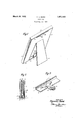
- FiggQ is a vertical sectiomof theflower portion of the frame, showingthe back-rel ing the back and the ⁇ velvet covering for the back, all greatly exaggerated as to thickness for purposes ofclarity.4 s i.
- Fig.g3 is ⁇ aiperspectivevlview 'of a portion of for removably securprovision of means consisting of a minimum Fig. 1 is aperspective View of an easel imma to .which mYHVQDtQDF-hbn api ated scale -as to thickness?- lDepen i-ing 'from the edge. 1.8, Whittie-:the-
- the frame 11 may be L-shaped in cross-"sec-f.Kv
- tab 10 is preferably madeofsheet metal and provided Awith a co-mparativelygwide sec- F tionv Lliand a narrowerrearwardly extending section 16 projecting beyond the lr'earjmos't edge-of the frame.
- Salid'sections 15 and"16 A are connected as by means ofI a suitablefllet l17 Y at the forward edge of theexten'sion secal 'tion 16, wheresaid section-is the vii'arrowest.y
- Tliefront orI wide section 1.5 may besecured ⁇ to the lower-most part of theflangef'l'in any y suitable manner, as byv means off solder 4or the' ⁇ y like, or by screws'or rivets Knotshownlg as", ⁇ may be ⁇ found convenient or desirableflItf will be seen that the extren'ierearward'edgeof the section 16 may be formed' into any suitable and appropriatedesignV forpurposes of ornamentation, and ,that the lower-'most' edge of the back ll and ofthe otherparts inserted into the frame may rest on Vthe se'ction 15, without the necessity ofv mutilating v the edges thereof. 4 is preferably so thin that it'dofesnot inter-'i fere with the proper 'support ofthevparts', ⁇
- a -fabric strip as 24 is secured totheface of thezrecess 22 and to the frontV face of,V the easel23, to limit the outward movement 'of theeasel, which is hinged to the barckat its upper edge. It ⁇ will be understood that where the frame is intended to behungup .and not to rest 'on a supporting surf-ace, the easel 23, the strip y2 4 ⁇ l; andthe recess 22may Vbe omitted.
- the vback 14 need'not tit tightly linto vthe p v 1 framegbetween thefflanges lrbut mayit comparatively loosely, j in distinction ,from
- part'.ofthevrearwardly extending flange,A said wide portionterminating inl' a comparatively narrow portion having ,outwardly diverging.
- the tab is bendable-about aline rearwardly of theY wideportion and forwardly ofthe rear edgeof theange to which said tab is secured through an angle of substan;
- a frame member In a picture frame, a frame member, a backing member fitted Vfrictionally into Vthe frame, means for securing said members together including a bendable tab havinga wide portion secured at its under face tothe upper face of the lowermost part of the frame mem-- ber and a narrower portion bendable into operative position at right angles tothe wide vportion for securing the backing member in place and a permanently arranged elongated member secured tothe upper part of the frame member and paralled to the front face of the frame member and adapted to 4engage the upper part of the rear face of the backing member in theV operative position of said backing member, and when said memberis tilted for insertion into the frame.
- a metallic frame having a front opening therein and a larger rear opening, a back of substantially the size of the rear opening and adapted to be inserted 'thereinto, a rigid member depending :from the top rear edge of the frame,"the length of said member being less than the width of the frame and the width of said member being greatest substantially at its middle point, aV bendable tab opposed to said rigid member at Y the lower edge of the frame ,and having a wide portion permanently ⁇ secured to the.
- bendable tab of sheet metal of negligible* 'y thickness having its under face secured to the upper facefo'f the lowermost rearwardly extending flange, said tab yhaving also acomparatively ⁇ narrow rear portion, the narrow-kv i" est portion of said tab ⁇ being arranged forwardlyof therear edgeof the rearwardlyv extendingflange to provide a bend linefor the tab-aty said narrowest portion, saidrigid member and said tab cooperating tol apply" forward pressure tothe rearlface of the back, and said lback and saidplatebeing' removable) ⁇ narrow portion of the tab toa horizontalposition continuous with the wide portion by first tilting the lowermost ⁇ edges ofl the bach v and the ,plate rearwardly ypast the tab and then lowering theback and the plate until the j f uppermost edges of-the lback and the plate lhave been 'dropped below V.the lowermost curved edge of the"v rigid member, vand anV easelV hinged to the ⁇ back and
Landscapes
- Mirrors, Picture Frames, Photograph Stands, And Related Fastening Devices (AREA)
Description
March 29, 1932.` H, L, BUDD f 1,851,492
FRAME TAB Filed May 19. 1950 INVENTOR fo wardl. Budd A A RNEY Patented Mar. 29,Y 1932 HOWARD L. Bunn, or nRooKLYN, New YORK, Assrenon INC., OF BRIO'OKL'YN,NEVI'v YORK, A CORPORATION'OF YORK FRAME TAB Y :application ined May 19,1930. serial n5453521( This invention relates to ornamental frames of the type adapted to hold a picture remov-V ably and intended to rest on an article 'of fur'- niture or to be hung up as on a wall, and de# i signed to present an-ornamental appearance. `In frames of this type, the frame `proper 1s made of metal, L-shapedl'in cross-section. A back is inserted into the frame fromthe rear for the purpose of holding the' glass andpic' ture in position. The back isrusually made of wood, cardboard or comparatively` inex-V pensive composition board of various types, and is `often completely covered with Avelvet or other ornamentalsheet material or fabric cemented thereto by a suitable glue or other adhesive. As the back of the frame should be' removable so that pictures may be placed.
therein or changed from time to time, means are preferably provided y 'ing the back infplace. Withoutvsuch means, the backmay shrink and become so loose as to fall out after a time, or it may swell and be-l: come wedged so tightly as to malre 1t diiiicult to remove when the frame is to beopened.VA 25 Forcible removal of the back may cause damage to the framewhen'the back is pred loose, and a loose back renders the frameA inoperae tive.
My invention therefore contemplates the number of parts, and requiring no skill in its operation, nor mutilation ofthe back or glass be clear from the description which follows,y
and from the drawings, wherein plied. y i, e e p. n
FiggQ is a vertical sectiomof theflower portion of the frame, showingthe back-rel ing the back and the `velvet covering for the back, all greatly exaggerated as to thickness for purposes ofclarity.4 s i. Fig.g3 is `aiperspectivevlview 'of a portion of for removably securprovision of means consisting of a minimum Fig. 1 is aperspective View of an easel imma to .which mYHVQDtQDF-hbn api ated scale -as to thickness?- lDepen i-ing 'from the edge. 1.8, Whittie-:the-
the frame showingthe bendable tab injinopl'- Q erative position.
' In that'practical embodiment of myinven-V` tion which I have ili'u'stratedby way of 4eX- ample, the usual metallic' frame is provided. 4
As illustrated, particularly, in Figs. Qiandf', Y
the frame 11 may be L-shaped in cross-"sec-f.Kv
tion, being providedwith the front flange l2 andthe.rearwardlyfextending flange 13 substantially atright anglesto each other.'v
To the lowermost-part of theiiange lof1 the'` frame, secure'a suitable, bendable tab-19,#v 'f preferably of thin metall oflsuiicifeiit length` to `vextend rearwardly ofthe iiangev 13 andto 'be turned upwardly into contactwith 'thej rear `face o f the back 14, to-holdthe lower` Vedgefof said 4backsecurely in position.: The
Tliefront orI wide section 1.5 may besecured` to the lower-most part of theflangef'l'in any y suitable manner, as byv means off solder 4or the'` y like, or by screws'or rivets Knotshownlg as",` may be `found convenient or desirableflItf will be seen that the extren'ierearward'edgeof the section 16 may be formed' into any suitable and appropriatedesignV forpurposes of ornamentation, and ,that the lower-'most' edge of the back ll and ofthe otherparts inserted into the frame may rest on Vthe se'ction 15, without the necessity ofv mutilating v the edges thereof. 4 is preferably so thin that it'dofesnot inter-'i fere with the proper 'support ofthevparts',`
rearmost edge of the., uppermost partfofthe i f1 13 s th Afi A'f" bn, taining, bendable tab,theloopfforfmanipulatfange 1b e Xe an' pre em 1y ngl'd Said section, however,
nov though illustrated inFig. Zonanxfexaggeri' Y' member? 19, 'also preferablyflmafie of aber i material and permanently secured` tf1-@Sup the" width of theV framelto provide outer portions lon the edge 18, free o-said member. `Thelowermost edge ofsaid member is suitv ably shaped for ornamental purposes and lill , ,eredwithvelvet 21 o'r other-[suitable'-orna-L *Y lmental fabric, shown in Fig. 2 Von a scale preferably has its greatest width at its mid dle part as at 20, said member being arranged 'substantially parallel to the front flange 12,
andbeing intended to engage the uppermost central portion of therear face of the back 111. As has been-indicated, the back lllis covg'reatly exaggerating `the thickness thereof, and is provided with a recess as 22 of the 15, same shape and extent as the easel 23, to re ceive.v the easel in the closed, folded' or in-k operative position thereof. A -fabric strip as 24 is secured totheface of thezrecess 22 and to the frontV face of,V the easel23, to limit the outward movement 'of theeasel, which is hinged to the barckat its upper edge. It `will be understood that where the frame is intended to behungup .and not to rest 'on a supporting surf-ace, the easel 23, the strip y2 4` l; andthe recess 22may Vbe omitted.
The vback 14 need'not tit tightly linto vthe p v 1 framegbetween thefflanges lrbut mayit comparatively loosely, j in distinction ,from
previous types ofsuch backs. which are de Vsigned-,to be forced into 5 place and'` retained in .positionj byfriction. YTo allow veasygre-` moval ofthe Vback 14arfabrieloop as 26s y secured ltothe lowermost edge-of the back at oneendg and isdesigned to be grippedby the-,user when the tabl() is inthe dotted 'line position indicatedin' Figi. 2, butsaid loopgis `alsoshown exaggerated in Athicknessin Fig;
y `To lassemble the variousparts in*l position, therglass .,27'is irstvarrangedin the frame vwith the frontface thereof in;` contact with' the rear face of. the flange'1-2.. ;The picture 28; :is then arranged in proper position;` on
the glass,afterfwhichV the back lfllis inserted yinto place. .To do this, the upper edgeof the backisfirstinserted in front of the member 19,the-lower edgeof the back being arranged rearwardly in spaced` relationv to theV frameand theback beingtherebytilted rearwardly. Thereafter, the lower edge of the back is swungforwardly into positionV inside of the. frameand against the pieture28.
' The extensionflof the tab 10 may now be .A y rotated from thepdotted linerposition shown inFig. 2,7up into contact with .the rear face y offtherrecess 22er therear facev of the back,
as Shown innige. 13nd 2. After the-tab i0. hasbeen bent upwardly againstatheback, it
will beseen that they backcannot fallouteventhough it: shrinks appreciably, since the members =10 and v19co-op'erate Vto k.prevent move-f, ment of the back .relatiyely vto the iframe. Tov
remove the backlaslfor example,`whenit is. de-
sired to change Athe picture 28, fthe i extension ,iksfglheriti .downwardly vintro( the dotted line position of Fig. 2 and the loop26 pulled rear wardly, thereby. disengaging the'k lower edge ofthe frame from the flangefl and allowing` the back to drop `downwardly out of'contact F70 Y with the member 19. It will be understood that the thicknesses of the velvet covering 21,Y
the loop 26, 'and the tablO, even whencombined, are negligibleand insucient to interfere to any substantial extent with the back inserting and removingoperations described;-
willbesfeenthat If have provided simple and effective means for removably holding the vback and other parts in place of the frame irrespective ,of the tightness of the itfof the 'back-andframe'.' VIt will further be seen that l-my improved-holding means may be'used repeatedly without' injury and that vit lis. welll designed to meet the severere practical use. y, While Ihave shown and described apa-rquirements :of Y
ticularembodiment of my, invention,;I-,donot Y wish to beA understood, as limiting myself;
thereto but intend to'cla-imjmy .invention as f 1 'i broadlyjas may be permitted "by `the state ofthe prior art an claims.V
I claimt f. .1.Inapicture d the terms ofthe; apI'Jendedl frame, afraine :member ,Lf shaped in cross-section-.and comprising afronta flange and a rearwardly extend-ingflangeV and having :a front openingtherein and aflargerrea-rY opening, `a'back vof .substantially the 'size Y of thewrear` opening ,and adapted to: hering-` serted thereintopand into friction'al engage-v Vment with theY rearwardly extending flange throughout the entire Vperipheryof SaidbaCk,"
said back having straightV unmutilatedfedge's -Y y throughout for )that purpose, ,a comparatively.
thin, rigid na'rrowielongated memberY depend? .ing ronrthe top rear edge of Ythe:rearwardly extending lange,fabendabletab of negligible( Y Y thickness adapted to lie-straightened to lie@y in a horizontal rplane and arranged belowv thel ,middle of the rigid member, said tabrhaving a widel .front portion having-its under; face secured tothe upper faceof the lowermost;
part'.ofthevrearwardly extending flange,A said wide portionterminating inl' a comparatively narrow portion having ,outwardly diverging.
edges-whereby the tab is bendable-about aline rearwardly of theY wideportion and forwardly ofthe rear edgeof theange to which said tab is secured through an angle of substan;
tially ,s'aid rigid, member and said'tabV eo!` *operatingto'l apply forwardy pressure tothe rear face `of the back, and said back bein'gre-klv movable from theframe on the'straightening of the narrow portion of the tab to a horizon! tal'position; continuous'lwith the .wide por# i edgeoftheback L-shaped incross-section, and having a front flange and a rearwardly disposed flange arranged at substantially right anglesto the front flange, of a metallic member secured to the rear edge of the uppermostrearwardly disposed flange and depending therefrom substantially parallel tothe frontpflange and of less length than the width ofthe frame,abacking member adapted to lltfrictionally into the frame inside of the rearwardly disposed flanges thereof and having straight, unmuti- Y lated edges, a glass plate havingunmutilated tively wealr bend line about which the ele-'1V ment is bent, and said element being adauted to cooperate with said metallic member to removably hold the backing member in place in the frame,the backing member being'removable on the straightening of the element and the rearwardly tilting of the member Vand the Vlowering of said member from its engagement with the metallic member.
3, In a picture frame, a frame member, a backing member fitted Vfrictionally into Vthe frame, means for securing said members together including a bendable tab havinga wide portion secured at its under face tothe upper face of the lowermost part of the frame mem-- ber and a narrower portion bendable into operative position at right angles tothe wide vportion for securing the backing member in place and a permanently arranged elongated member secured tothe upper part of the frame member and paralled to the front face of the frame member and adapted to 4engage the upper part of the rear face of the backing member in theV operative position of said backing member, and when said memberis tilted for insertion into the frame.
ll. In a picture frame, a metallic frame having a front opening therein and a larger rear opening, a back of substantially the size of the rear opening and adapted to be inserted 'thereinto, a rigid member depending :from the top rear edge of the frame,"the length of said member being less than the width of the frame and the width of said member being greatest substantially at its middle point, aV bendable tab opposed to said rigid member at Y the lower edge of the frame ,and having a wide portion permanently` secured to the.
frame and a comparatively narrowportion extending rearwardly therefrom and adapti ed to be bent throughv an angle of substantially against the back4 to cooperate `with the rigidV member to removably secure the i 4back in place.
5. In a picture frame, asubstantially recsection and comprising front flanges and rearl wardly extending flanges,and having a front y opening therein betweenv the'front flanges Y j anda larger rear opening between the rear flanges, a velvet covered back'of substantially the same size and shape as that-ofv the rear.
opening and adapted to be inserted into the rear opening with the `edges and ends thereof in frictional engagement with the rearwardly extending flanges, said back having straight unmutilated edges and ends, a glass plate having unmutilated -edges and ends and v of substantially the same size andvshape as that of the back arranged between the back and the'- front flanges, a comparatively thin rigid elongated member having a straight upper edgev soldered. to the lower face of the uppermost rearwardly. extending flange of the frame and depending therefrom, andof less length `than the width of the frame, a"
bendable tab of sheet metal of negligible* 'y thickness having its under face secured to the upper facefo'f the lowermost rearwardly extending flange, said tab yhaving also acomparatively` narrow rear portion, the narrow-kv i" est portion of said tab` being arranged forwardlyof therear edgeof the rearwardlyv extendingflange to provide a bend linefor the tab-aty said narrowest portion, saidrigid member and said tab cooperating tol apply" forward pressure tothe rearlface of the back, and said lback and saidplatebeing' removable)` narrow portion of the tab toa horizontalposition continuous with the wide portion by first tilting the lowermost` edges ofl the bach v and the ,plate rearwardly ypast the tab and then lowering theback and the plate until the j f uppermost edges of-the lback and the plate lhave been 'dropped below V.the lowermost curved edge of the"v rigid member, vand anV easelV hinged to the `back and adapted to conceal the tab when the easel is in its inoperative position. l
'nowiinn L. Bunn.V
from the frame on the straightening olfl the n 70 tangular frame member L-shaped in cross-
Priority Applications (1)
| Application Number | Priority Date | Filing Date | Title |
|---|---|---|---|
| US453521A US1851492A (en) | 1930-05-19 | 1930-05-19 | Frame tab |
Applications Claiming Priority (1)
| Application Number | Priority Date | Filing Date | Title |
|---|---|---|---|
| US453521A US1851492A (en) | 1930-05-19 | 1930-05-19 | Frame tab |
Publications (1)
| Publication Number | Publication Date |
|---|---|
| US1851492A true US1851492A (en) | 1932-03-29 |
Family
ID=23800880
Family Applications (1)
| Application Number | Title | Priority Date | Filing Date |
|---|---|---|---|
| US453521A Expired - Lifetime US1851492A (en) | 1930-05-19 | 1930-05-19 | Frame tab |
Country Status (1)
| Country | Link |
|---|---|
| US (1) | US1851492A (en) |
Cited By (3)
| Publication number | Priority date | Publication date | Assignee | Title |
|---|---|---|---|---|
| US5253440A (en) * | 1992-09-14 | 1993-10-19 | Thomas Chang | Structure of a picture frame |
| USD487782S1 (en) | 2000-07-25 | 2004-03-23 | Kevin M. Watkins | Dry-erase tent card support stand |
| US20150075046A1 (en) * | 2012-03-14 | 2015-03-19 | Garmond Pty. Ltd. | Retainer member for a picture frame |
-
1930
- 1930-05-19 US US453521A patent/US1851492A/en not_active Expired - Lifetime
Cited By (3)
| Publication number | Priority date | Publication date | Assignee | Title |
|---|---|---|---|---|
| US5253440A (en) * | 1992-09-14 | 1993-10-19 | Thomas Chang | Structure of a picture frame |
| USD487782S1 (en) | 2000-07-25 | 2004-03-23 | Kevin M. Watkins | Dry-erase tent card support stand |
| US20150075046A1 (en) * | 2012-03-14 | 2015-03-19 | Garmond Pty. Ltd. | Retainer member for a picture frame |
Similar Documents
| Publication | Publication Date | Title |
|---|---|---|
| US2091203A (en) | Mirror | |
| US1851492A (en) | Frame tab | |
| US1253803A (en) | Picture-frame. | |
| US1560493A (en) | Holder | |
| US903050A (en) | Easel. | |
| US949328A (en) | Display-frame for cards. | |
| US415552A (en) | Photograph-frame | |
| US3203552A (en) | Desk mount | |
| US1892014A (en) | Picture frame | |
| US1208687A (en) | Copy-holder. | |
| US236371A (en) | Hand-mirror | |
| US1741434A (en) | Advertising device | |
| US1681092A (en) | Display box | |
| US1702263A (en) | Picture frame | |
| US1754814A (en) | Frame clip | |
| US756013A (en) | Paper-pad holder. | |
| US3080603A (en) | Picture frame structure | |
| US1049428A (en) | Memorandum-pad calendar. | |
| US1232095A (en) | Picture-frame. | |
| US1654555A (en) | Card index | |
| US1248976A (en) | Combined military mirror and button-stick. | |
| US778748A (en) | Sign. | |
| US946728A (en) | Shaving-paper holder. | |
| US421101A (en) | Joseph manheimer | |
| US1357321A (en) | Cracker-can |