US1851345A - Weld testing machine - Google Patents
Weld testing machine Download PDFInfo
- Publication number
- US1851345A US1851345A US322410A US32241028A US1851345A US 1851345 A US1851345 A US 1851345A US 322410 A US322410 A US 322410A US 32241028 A US32241028 A US 32241028A US 1851345 A US1851345 A US 1851345A
- Authority
- US
- United States
- Prior art keywords
- tube
- piston
- heads
- carried
- jaws
- Prior art date
- Legal status (The legal status is an assumption and is not a legal conclusion. Google has not performed a legal analysis and makes no representation as to the accuracy of the status listed.)
- Expired - Lifetime
Links
Images
Classifications
-
- G—PHYSICS
- G01—MEASURING; TESTING
- G01N—INVESTIGATING OR ANALYSING MATERIALS BY DETERMINING THEIR CHEMICAL OR PHYSICAL PROPERTIES
- G01N3/00—Investigating strength properties of solid materials by application of mechanical stress
-
- G—PHYSICS
- G01—MEASURING; TESTING
- G01N—INVESTIGATING OR ANALYSING MATERIALS BY DETERMINING THEIR CHEMICAL OR PHYSICAL PROPERTIES
- G01N2203/00—Investigating strength properties of solid materials by application of mechanical stress
- G01N2203/02—Details not specific for a particular testing method
- G01N2203/026—Specifications of the specimen
- G01N2203/0296—Welds
Definitions
- This invention relates to an improved machine for testing the mechanical strength of welded joints.
- This invention finds a special field of usefulness in connection with the r. testing of welded tubes, particularly tubes of the type which are utilized in connection with the boiler construction of steam propelled locomotives.
- the short sections are secured to the main body of each tube or flue by welding operations.
- welding operations using preferably the so-called lapjoint type of weld
- Considerable difficulty has been encountered. however, in the matter of properly testing the mechanical strength of the tubes or flues after the welding operation.
- Such a test has been genorally unsatisfactory and inconclusive for the reason that when the tubes are subsequently placed in a boiler, the end plates or sheets to which they are attached under operating conditions, have a tendency to spread apart, due in all probability to the steam pressure developed within the boiler.
- each tube or fine under process of testing is subjected to tensile stress so that the strength of the welded joint in this connection may be determined during the testing operation, which consists in subjecting the tube or flue to approximately the same conditions of stress and strain as it receives when subsequently used in boiler construction.
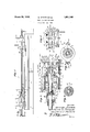
- Figure 1 is a view in side elevation of a flue testing machine formed in accordance with the present invention
- Figure 2 is a horizontal sectional view, the plane of whichbeing disclosed by the line 22 of Figure 1,
- Figure?) is a transverse sectional view taken on the plane indicated by the line 3-3 of Figure 1,
- FIG. 4 is a similar view on the line 4-4 of Figure 2,
- Figure 5 is a transverse sectional view on the line 5-5 of Figure 1.
- the numeral 1 designates the bed frame of the improved testing machine comprising the invention.
- This frame preferably consists of transversely spaced longitudinally extending channel members 22 which are supported by means of legs 3.
- supporting heads 4 which are adapted to receive and support between them a tube or flue section 5 which is to be tested so as to determine the strength of a welded joint, indicated at 6, provided therein.
- Each head comprises a cylindrical housing 7 formed atone end with a longitudinally extending chamber 8 in which is slidably mounted a piston 9.
- This piston is rigidly connected by means of a threaded securing nut 9 with a tubular supporting core 10 which extends through a stufling box 11 bolted or otherwise secured to one end of the chamber 8.
- the core 10 is also slidably received within a bearing opening provided in the wall 12 at the other end of the chamber 8. and confined between the wall 12 and the piston 9 and surrounding the core 10 is a helical spring 13, the normal function of which is to force the piston 9, and with it the core 10, toward the box end 11 of the chamber 8.
- Compressed air under a pressure of approximately 100 pounds per square inch may be introduced into the chamber 8 so as to force the piston toward the wall 12 in opposition to the spring 13, said air being admitted into the chambers 8 of each of the supporting heads 4 by means of valve pipe lines 14, extending from any suitable source of compressed air supply.
- Each of the heads 4 is further formed to include an inner chamber 15, in which is slidably mounted a piston 16, the latter being formed to include an elongated tubular stem 17.
- This stem. is adapted to slidably receive the inner portion of the core 10, there being a helical spring 18 between the wall 12 and the outer face of the piston 16, the said spring 18 surrounding the core 10 and its normal function is to force the piston 16 inwardlv'or in a direction toward the tube or fine 5.
- the chambers 8 and 15 may be vented as at 18 to the atmosphere to prevent the formation of air cushions on the opposite sides of the pistons from the pressure side.
- each of the cores 10 is provided with a removable seating element 19, which is provided with a convex face 20 adapted to engage with the end of the tube 5.
- the element 19 may be formed from a material softer than that comprising the core 10 so as to avoid injury to the end of the tube or flue and to form a seal during process of testing.
- the ends of the stems 17 which project beyond the glands 22, are internally threaded for the reception of collars 28.
- the ad acent faces of the jaws 25 are provided with semi-circular pockets of radii which make them conformable with the diameter of the tube or fine 5.
- the jaws 25 are further formed to include angularly disposed surfaces 26. which lie at acute angles with respect to the axis of the tube These surfaces are adapted to engage with rollers 27 which are carried by brackets 28 slidably mounted upon longitudinally extending bars 29 which are ri idly connected with and form a part of the heads 4:.
- the brackets 28 are slidably connected with the bars 29 by means of belts or their equivalents '80, the latter being niovm ble in elongated slots provided in said bars as at 31.
- the brackets 28 engage at the opposed ends with rubber buffers or cushion blocks 32, which blocks are carried by metallic blocks 33 which are bolted or otherwise stationarily fastened in a rigid manner to the inner surfaces of the bars 29% It will be seen that when compressed air under superatmospheric pressure of approximately 100 pounds per square inch is introduced into the cylinders 15, the stems 17 connected with the piston 16 will be drawn inwardly towards the wall 12, moving with them the clamping jaws 25. This inward movement on the part of the clamping jaws causes them to engage with the rollers 27 carried by the brackets 28, forcing the latter outwardly into firm engagement with the bars 29. and at the same time moving said jaws inwardly into frictional clamping engagement with the ends of the tubes or line sections 5.
- a transversely extending brace 33 which is arranged below the flue section 5 and has its into one of the cores by way of the valved flexible conduit 35 and a pressure gauge 36 may be provided on the other of said cores to permit the internal pressures which obtain in the cores to be readily noted. Similar gauges may, of course, be provided for determining the air pressures which exist in the chambers 8 and 15.
- the cushion blocks or buffers 32 permit of slight longitudinal movement of the brackets 28 in the event the tensile stresses applied to the tube or flue section indicates a Weakness in the joint 6. If this joint should part but slightly under the tests afforded by the machine,
- the slight degree of movement thus afforded is-taken up by the buffers 32.
- the buffers 32 permit a gap of small dimensions to be formed in the welded joint, permitting the internal liquid to escape, and the presence of the faulty joint may be determined either by noting the decrease in the pressure of the -water, as indicated by the gauge 36, or by observing the esca e of the water through the joint.
- the springs 13 and 18 return the pistons 9 and 16 to normal positions following the release of compressed air from the chambers 8 and 15.
- Coil springs are positio'ned on the pins forming the pivots 24 and have one of their ends held stationary with the collar 23 and the other of its ends connected to the pivot pins 24 which are movable with the jaws 25. It will thus be seen that the springs which are so connected will be given a torsional twist when the jaws 25 engage with the rollers 27 and when removed from engagement with said rollers will move the aws to an open position.
- the present invention provides a testing machine which is efliciently adapted for the purpose of testing the strength of welded tube joints.
- the invention may be used to considerable advantage in locomotive repair shops or in any other capacity, wherein welded pipe members are employed.
- the invention is not limited, of course, to the precise structural arrangements above specifically described and illustrated in the accompanying drawings, and it should be understood that the invention is susceptible to considerable mechanical change and modifications without departing from the spirit or scope thereof, the true scope of the invention being pointed out in the subjoined claims.
- a tube testing apparatus a supporting frame, a head carried by said frame and provided with a pair of axially aligned tubular chambers, a piston movably mounted in each of said chambers, a tube supporting member carried 'by one of said pistons, tube gripping members carried by the otherof said pistons, means for introducing fluid pressure into said chambers to maintain said supporting member in frictional engagement with one end of a tube to be tested and for exerting a tensile stress upon said tube, means for admitting of the introduction of a liquid under pressure in said tube, and spring means for returning said pistons to positions releasing said tube gripping members and tube supporting member from engagement with saidtube.
- a tube testing apparatus a supporting frame, a head carried by said frame and provided with a pair of axially aligned tubular chambers, a piston mounted for sliding movement in each of said chambers.
- a tube supporting member carried by one of said pistons
- tube gripping members carried by the other of said pistons
- means for admitting of the introduction of the liquid under superatmospheric pressure into the tube to be tested
- a supporting frame a pair of heads carried by said frame, an axiallv movable tubular supporting member carr ed by each of said heads and arranged to frictionally engage with the ends of a tube confined between said heads, means for introducing fluid pressure into said heads and against said su porting members to mainta n the latter in frictional engagement with the ends of said tube, gripping members carried by each of said heads and arranged to en age with the ends of said tube. and means responsive to the action of a fluid under superatmospheric pressure to cause said gripping members to exert tensile stress upon the tube engaged thereby.
- a frame a pair of supporting heads spaced longitudinally upon said frame and adapted to receive between them a tube having a welded joint, each of said heads being provided with a chamber, a piston slidably mounted within said chamber and provided with an exteriorly projecting stem, a pair of clamping jaws pivotally connected with the outer end of said stem, said jaws being engageable with said tube, means engageable with said jaws for forcing the latter to grip in engagement with said tube, and means for introducing compressed air into said chamber and to force said jaws into engagement with said tube and to impart tensile stressto said tube.
- a frame a supporting head carried by said frame and provided with an internal chamber, a piston slidably mounted within said chamber, said piston being provided with an exteriorly projecting stem, a pair of clamping jaws pivotal ly carried by the exterior portion of said stem, brackets slidably mounted in connection with said head and provided with rollers engageable with said jaws, means for introducing compressed air into said chamber whereby to force said jaws into engagement with said rollers and thereby maintain the jaws in clamping engagement with said tube and impart tensile stress to said tube, and yieldable buffers engageable with said brackets for admitting of limited sliding movement of said brackets in one direction.
- a frame a supporting head carried by said frame and provided with an internal chamber, a piston slidably mounted within said chamber, said piston being provided with an externally projecting stem, a pair of clamping jaws pivotally carriedby the exterior portion of said stem.
- means carried by the head for engaging said jaws, means for introducing compressed air into said chamber whereby action on the piston will force said jaws intoengagement with said jaw ans and thereby maintain the jaws in cia o ng engagement with said and i part tensile stress thereto, a tube supporting member carried by said head and arranged to frictionally engage with the and of the tube, and means for passing a liquid under relatively high pressure into said tube while the latter is being maintainedunder conditions imparting tensile stress thereto.
- a frame a pair of spaced hollow h ids carried. rigidlv by said frame, a piston each of said heads, an axially movab' member carried by ea ar 'anged to frictions-by e of the tube confined between said heads, means for introducing fluid pressure into said heads and against said pistons to maintain said supporting members in frictional en-.
- a frame a pair of spaced hollow heads carried rigidly by said frame, a piston within each of said heads, an axially movable tubular supporting member carried by each of said heads and arranged to frictionally engage with the ends of the tube confined between said heads, means for introducing fluid pressure into said heads and against said pistons to maintain said supporting members in frictional ehgagement with the ends of said tube, tube gripping members slidably carried by each of said heads and acting in opposition to said tube supporting members to place the tube under tensile stress, and yieldable means carried by said heads and associated with said gripping members for admitting of limited sliding movement of the latter while imparting tensile stress to said tube.
- a frame a supporting head carried by said frame and provided with a pair of axially aligned tubular members, a piston slidably mounted in each of said chambers, one of said pistons having an exterior portion arranged to frictionally' engage with the end of the tube and serving as a support therefor, said piston being acted on by fluid pressure to hold said support in connection with said tube, the other of said pistons being provided with an externally projecting stem, clamping jaws pivotally connected with the outer end of said stem, said jaws being engagable with said tube, means carried by said head and .engagable with said jaws for forcing the latter into gripping engagement with said tube, means for introducing fluid pressure into the chamber for the last named piston to impart i tensile stress to the tube, and means admitting of the introduction of a liquid under pressure into said tube.
- a support ing frame a head carried by said frame and provided with a pair of axially aligned tubular chambers, a slidable piston mounted in each of said chambers, one of said pistons.
Landscapes
- Physics & Mathematics (AREA)
- Health & Medical Sciences (AREA)
- Life Sciences & Earth Sciences (AREA)
- Chemical & Material Sciences (AREA)
- Analytical Chemistry (AREA)
- Biochemistry (AREA)
- General Health & Medical Sciences (AREA)
- General Physics & Mathematics (AREA)
- Immunology (AREA)
- Pathology (AREA)
- Investigating Strength Of Materials By Application Of Mechanical Stress (AREA)
Description
March 29, 1932. 6. BROWN ET AL WELD TESTING MACHINE Filed Nov. 28, 1928 d-Wommq soryefiroma Owen 17. 1B0 ach flerrnan fl gfers Z KMW Patented Mar. 2%, 1932 GEORGE BROWN, OWEN E. ROACH, AND HERMAN J. PETERS, OF COLUMBUS, OHIO WELD TESTING MACHINE Application filed November 28, 1928, Serial No. 322,410.
This invention relates to an improved machine for testing the mechanical strength of welded joints. This invention finds a special field of usefulness in connection with the r. testing of welded tubes, particularly tubes of the type which are utilized in connection with the boiler construction of steam propelled locomotives.
In locomotive boilers it is customary to h! utilizea plurality of parallel tubes or flues through which pass the heated furnace gases, the flues being surrounded by water used in the development of steam so that the heat of the furnace gases may be readily transferred 1?) to the liquid medium surrounding the tubes for steam generating purposes. These tubes or flues have their ends connected with and supported by end plates or boiler sheets. From time to time in the service of boilers of this character the tubes are removed from connection with the boiler sheets by transversly severing the tubes at positions contiguous to the boiler sheets. Then. in order to salvage the tubes and to render them suitable for subsequent re-employment in a boiler, relatively short lengths or sections are welded to the ends of the main bodies of the tubes to replace the short lengths which were removed by the severing operation.
The short sections are secured to the main body of each tube or flue by welding operations. using preferably the so-called lapjoint type of weld Considerable difficulty has been encountered. however, in the matter of properly testing the mechanical strength of the tubes or flues after the welding operation. Heretofore it has been customary to place the tubes in a supporting frame and subjecting the same to the action of internally introduced hydraulic pressure to determine the efiiciency or strength of the welded joint. Such a test. however, has been genorally unsatisfactory and inconclusive for the reason that when the tubes are subsequently placed in a boiler, the end plates or sheets to which they are attached under operating conditions, have a tendency to spread apart, due in all probability to the steam pressure developed within the boiler. Due to this influence the boiler flues or tubes are placed under tensile stress of a very considerable proportion, thus introducing a factor of stress into the welded joint which was not present during the testing operation, with the result that many-joints develop, in practice, weaknesses and imperfections which were not apparent when the welded tube or flue was originally subjected to test,
In accordance with the present invention an improved testing machine is provided wherein each tube or fine under process of testing, is subjected to tensile stress so that the strength of the welded joint in this connection may be determined during the testing operation, which consists in subjecting the tube or flue to approximately the same conditions of stress and strain as it receives when subsequently used in boiler construction.
For a further understanding of the invention reference is to be had to the following description and the accompanying drawings, wherein:
Figure 1 is a view in side elevation of a flue testing machine formed in accordance with the present invention,
Figure 2 is a horizontal sectional view, the plane of whichbeing disclosed by the line 22 of Figure 1,
Figure?) is a transverse sectional view taken on the plane indicated by the line 3-3 of Figure 1,
Figure 4 is a similar view on the line 4-4 of Figure 2,
Figure 5 is a transverse sectional view on the line 5-5 of Figure 1.
Referring more particularly to the drawings. the numeral 1 designates the bed frame of the improved testing machine comprising the invention. This frame preferably consists of transversely spaced longitudinally extending channel members 22 which are supported by means of legs 3.
Mounted upon the channel members 2 at each end of the machine are supporting heads 4 which are adapted to receive and support between them a tube or flue section 5 which is to be tested so as to determine the strength of a welded joint, indicated at 6, provided therein.
Each head comprises a cylindrical housing 7 formed atone end with a longitudinally extending chamber 8 in which is slidably mounted a piston 9. This piston is rigidly connected by means of a threaded securing nut 9 with a tubular supporting core 10 which extends through a stufling box 11 bolted or otherwise secured to one end of the chamber 8. The core 10 is also slidably received within a bearing opening provided in the wall 12 at the other end of the chamber 8. and confined between the wall 12 and the piston 9 and surrounding the core 10 is a helical spring 13, the normal function of which is to force the piston 9, and with it the core 10, toward the box end 11 of the chamber 8. Compressed air under a pressure of approximately 100 pounds per square inch may be introduced into the chamber 8 so as to force the piston toward the wall 12 in opposition to the spring 13, said air being admitted into the chambers 8 of each of the supporting heads 4 by means of valve pipe lines 14, extending from any suitable source of compressed air supply.
Each of the heads 4 is further formed to include an inner chamber 15, in which is slidably mounted a piston 16, the latter being formed to include an elongated tubular stem 17. This stem. is adapted to slidably receive the inner portion of the core 10, there being a helical spring 18 between the wall 12 and the outer face of the piston 16, the said spring 18 surrounding the core 10 and its normal function is to force the piston 16 inwardlv'or in a direction toward the tube or fine 5. The chambers 8 and 15 may be vented as at 18 to the atmosphere to prevent the formation of air cushions on the opposite sides of the pistons from the pressure side.
The inner end of each of the cores 10 is provided with a removable seating element 19, which is provided with a convex face 20 adapted to engage with the end of the tube 5. The element 19 may be formed from a material softer than that comprising the core 10 so as to avoid injury to the end of the tube or flue and to form a seal during process of testing.
It will be seen that in clamping the tube or flue between the cores 10 of the sup orting heads l, and in axial alignment with such cores. air is introduced into the chambers 8. thereby moving the pistons 9 inwardly against the resistance of the springs 13. In this manner the cores move into clamping engagement with the ends of the flue or tube to be tested, thus holding the tube'in an operative or testing position.
Following this operation compressed air or the like under a pressure, for example, 100 pounds per square inch, is introduced into each of the chambers 15 between the piston 16 and the end Walls 21 of the heads 4. These latter walls are bolted to the covers 7 and provided with packing glands 22 for the slidable reception of the tubular stems 17 of the pistons 16. The'introduction of the compressed air into the cylinders or chambers 15 results in moving the pistons 16 outwardly against the resistance offered by the springs 18..
The ends of the stems 17 which project beyond the glands 22, are internally threaded for the reception of collars 28. To each of these collars there is pivotally connected. as at 2 a pair of tube clamping jaws 25. The ad acent faces of the jaws 25 are provided with semi-circular pockets of radii which make them conformable with the diameter of the tube or fine 5. The jaws 25 are further formed to include angularly disposed surfaces 26. which lie at acute angles with respect to the axis of the tube These surfaces are adapted to engage with rollers 27 which are carried by brackets 28 slidably mounted upon longitudinally extending bars 29 which are ri idly connected with and form a part of the heads 4:. The brackets 28 are slidably connected with the bars 29 by means of belts or their equivalents '80, the latter being niovm ble in elongated slots provided in said bars as at 31.
The brackets 28 engage at the opposed ends with rubber buffers or cushion blocks 32, which blocks are carried by metallic blocks 33 which are bolted or otherwise stationarily fastened in a rigid manner to the inner surfaces of the bars 29% It will be seen that when compressed air under superatmospheric pressure of approximately 100 pounds per square inch is introduced into the cylinders 15, the stems 17 connected with the piston 16 will be drawn inwardly towards the wall 12, moving with them the clamping jaws 25. This inward movement on the part of the clamping jaws causes them to engage with the rollers 27 carried by the brackets 28, forcing the latter outwardly into firm engagement with the bars 29. and at the same time moving said jaws inwardly into frictional clamping engagement with the ends of the tubes or line sections 5. This results in placing the tube or flue section under tensile stress in order to test the strength or weaknesses of the welded ioint 6 therein. To prevent spreadill-5 ing of the outer ends of the bars 29 during the engagement of the clamping jaws 25 with the rollers 27, there is provided a transversely extending brace 33 which is arranged below the flue section 5 and has its into one of the cores by way of the valved flexible conduit 35 and a pressure gauge 36 may be provided on the other of said cores to permit the internal pressures which obtain in the cores to be readily noted. Similar gauges may, of course, be provided for determining the air pressures which exist in the chambers 8 and 15. The cushion blocks or buffers 32 permit of slight longitudinal movement of the brackets 28 in the event the tensile stresses applied to the tube or flue section indicates a Weakness in the joint 6. If this joint should part but slightly under the tests afforded by the machine,
. the slight degree of movement thus afforded is-taken up by the buffers 32. The buffers 32 permit a gap of small dimensions to be formed in the welded joint, permitting the internal liquid to escape, and the presence of the faulty joint may be determined either by noting the decrease in the pressure of the -water, as indicated by the gauge 36, or by observing the esca e of the water through the joint. The springs 13 and 18 return the pistons 9 and 16 to normal positions following the release of compressed air from the chambers 8 and 15. Coil springs are positio'ned on the pins forming the pivots 24 and have one of their ends held stationary with the collar 23 and the other of its ends connected to the pivot pins 24 which are movable with the jaws 25. It will thus be seen that the springs which are so connected will be given a torsional twist when the jaws 25 engage with the rollers 27 and when removed from engagement with said rollers will move the aws to an open position.
In view of the foregoing it will be seen that the present invention provides a testing machine which is efliciently adapted for the purpose of testing the strength of welded tube joints. The invention may be used to considerable advantage in locomotive repair shops or in any other capacity, wherein welded pipe members are employed. The invention is not limited, of course, to the precise structural arrangements above specifically described and illustrated in the accompanying drawings, and it should be understood that the invention is susceptible to considerable mechanical change and modifications without departing from the spirit or scope thereof, the true scope of the invention being pointed out in the subjoined claims.
What is claimed is:
1. In a tube testing apparatus, a supporting frame, a head carried by said frame and provided with a pair of axially aligned tubular chambers, a piston movably mounted in each of said chambers, a tube supporting member carried 'by one of said pistons, tube gripping members carried by the otherof said pistons, means for introducing fluid pressure into said chambers to maintain said supporting member in frictional engagement with one end of a tube to be tested and for exerting a tensile stress upon said tube, means for admitting of the introduction of a liquid under pressure in said tube, and spring means for returning said pistons to positions releasing said tube gripping members and tube supporting member from engagement with saidtube.
2. In a tube testing apparatus, a supporting frame, a head carried by said frame and provided with a pair of axially aligned tubular chambers, a piston mounted for sliding movement in each of said chambers. a tube supporting member carried by one of said pistons, tube gripping members carried by the other of said pistons, means ,for introducing fluid pressure into said chambers to maintain said supporting member in frictional engagement with one end of a tube and for exerting a tensile stress upon the tube engaged therebv, means for admitting of the introduction of the liquid under superatmospheric pressure into the tube to be tested, and means for effecting the automatic release of said tube gripping members and supporting member from engagement with said tube upon the completion of said test.
3. In a weld testing machine. a supporting frame. a pair of heads carried by said frame, an axiallv movable tubular supporting member carr ed by each of said heads and arranged to frictionally engage with the ends of a tube confined between said heads, means for introducing fluid pressure into said heads and against said su porting members to mainta n the latter in frictional engagement with the ends of said tube, gripping members carried by each of said heads and arranged to en age with the ends of said tube. and means responsive to the action of a fluid under superatmospheric pressure to cause said gripping members to exert tensile stress upon the tube engaged thereby.
4. In a weld testing machine. a frame, a
pair of supporting heads carried by sa d.
and engageable with the ends of said tube to support and place the latter under tensile stress, and means admitting of the introduction of a liquid under pressure into said tube.
5. In a tube testing machine, a frame, a pair of supporting heads spaced longitudinally upon said frame and adapted to receive between them a tube having a welded joint, each of said heads being provided with a chamber, a piston slidably mounted within said chamber and provided with an exteriorly projecting stem, a pair of clamping jaws pivotally connected with the outer end of said stem, said jaws being engageable with said tube, means engageable with said jaws for forcing the latter to grip in engagement with said tube, and means for introducing compressed air into said chamber and to force said jaws into engagement with said tube and to impart tensile stressto said tube.
6. In a weld testing machine, a frame, a supporting head carried by said frame and provided with an internal chamber, a piston slidably mounted within said chamber, said piston being provided with an exteriorly projecting stem, a pair of clamping jaws pivotal ly carried by the exterior portion of said stem, brackets slidably mounted in connection with said head and provided with rollers engageable with said jaws, means for introducing compressed air into said chamber whereby to force said jaws into engagement with said rollers and thereby maintain the jaws in clamping engagement with said tube and impart tensile stress to said tube, and yieldable buffers engageable with said brackets for admitting of limited sliding movement of said brackets in one direction.-
7. In a tube testing machine, a frame, a supporting head carried by said frame and provided with an internal chamber, a piston slidably mounted within said chamber, said piston being provided with an externally projecting stem, a pair of clamping jaws pivotally carriedby the exterior portion of said stem. means carried by the head for engaging said jaws, means for introducing compressed air into said chamber whereby action on the piston will force said jaws intoengagement with said jaw ans and thereby maintain the jaws in cia o ng engagement with said and i part tensile stress thereto, a tube supporting member carried by said head and arranged to frictionally engage with the and of the tube, and means for passing a liquid under relatively high pressure into said tube while the latter is being maintainedunder conditions imparting tensile stress thereto.
8. In a tube testing machine, a frame, a pair of spaced hollow h ids carried. rigidlv by said frame, a piston each of said heads, an axially movab' member carried by ea ar 'anged to frictions-by e of the tube confined between said heads, means for introducing fluid pressure into said heads and against said pistons to maintain said supporting members in frictional en-.
said tube.
9. In a tube testing machine, a frame, a pair of spaced hollow heads carried rigidly by said frame, a piston within each of said heads, an axially movable tubular supporting member carried by each of said heads and arranged to frictionally engage with the ends of the tube confined between said heads, means for introducing fluid pressure into said heads and against said pistons to maintain said supporting members in frictional ehgagement with the ends of said tube, tube gripping members slidably carried by each of said heads and acting in opposition to said tube supporting members to place the tube under tensile stress, and yieldable means carried by said heads and associated with said gripping members for admitting of limited sliding movement of the latter while imparting tensile stress to said tube.
10. In a tube testing apparatus, a frame, a supporting head carried by said frame and provided with a pair of axially aligned tubular members, a piston slidably mounted in each of said chambers, one of said pistons having an exterior portion arranged to frictionally' engage with the end of the tube and serving as a support therefor, said piston being acted on by fluid pressure to hold said support in connection with said tube, the other of said pistons being provided with an externally projecting stem, clamping jaws pivotally connected with the outer end of said stem, said jaws being engagable with said tube, means carried by said head and .engagable with said jaws for forcing the latter into gripping engagement with said tube, means for introducing fluid pressure into the chamber for the last named piston to impart i tensile stress to the tube, and means admitting of the introduction of a liquid under pressure into said tube.
11. In a tube testing apparatus, a support ing frame, a head carried by said frame and provided with a pair of axially aligned tubular chambers, a slidable piston mounted in each of said chambers, one of said pistons.
being provided with a stem projecting through the chamber for the other of said pistons and having its exterior portion arranged to frictionally engage with one end of the tube and acting as a support therefor when fluid pressure is being applied thereto. the other of said pistons having its projecti d to slide upon the stem of the first named piston and having a portion thereof projecting exteriorly of said head a. pair of clamping jaws pivotally carried hy said exterior portion of said stem, said jaws 5 being engagable with said tube, means carried by said head and engagable with said jaws for forcing the latter into gripping engagement with said tube, and means for applying fluid pressure to the piston carrying the 10 clamping jaws during their engagement with the tube for imparting tensile stress thereto.
In testimony whereof we aflix our signatures. v
' GEORGE BROWN. OWEN E. ROAGH. HERMAN J. PETERS.
Priority Applications (1)
| Application Number | Priority Date | Filing Date | Title |
|---|---|---|---|
| US322410A US1851345A (en) | 1928-11-28 | 1928-11-28 | Weld testing machine |
Applications Claiming Priority (1)
| Application Number | Priority Date | Filing Date | Title |
|---|---|---|---|
| US322410A US1851345A (en) | 1928-11-28 | 1928-11-28 | Weld testing machine |
Publications (1)
| Publication Number | Publication Date |
|---|---|
| US1851345A true US1851345A (en) | 1932-03-29 |
Family
ID=23254762
Family Applications (1)
| Application Number | Title | Priority Date | Filing Date |
|---|---|---|---|
| US322410A Expired - Lifetime US1851345A (en) | 1928-11-28 | 1928-11-28 | Weld testing machine |
Country Status (1)
| Country | Link |
|---|---|
| US (1) | US1851345A (en) |
Cited By (7)
| Publication number | Priority date | Publication date | Assignee | Title |
|---|---|---|---|---|
| US2445876A (en) * | 1945-03-31 | 1948-07-27 | Baldwin Locomotive Works | Apparatus for testing tubes by fluid pressure |
| US2493061A (en) * | 1946-07-23 | 1950-01-03 | John U Devine | Hydraulic pipe testing machine |
| US3350920A (en) * | 1964-05-16 | 1967-11-07 | Kieserling & Albrecht | Apparatus for testing tubular workpieces |
| US3350921A (en) * | 1964-01-22 | 1967-11-07 | Kieserling & Albrecht | Apparatus for testing tubes |
| US4416147A (en) * | 1981-07-15 | 1983-11-22 | Hasha Brian B | Apparatus and method for hydrostatically testing pipe |
| US5419184A (en) * | 1993-09-28 | 1995-05-30 | Pace; Floyd E. | Hydrostatic pressure testing apparatus |
| EP1836472A4 (en) * | 2004-12-30 | 2010-03-31 | Car Ber Investments Inc | Method and apparatus for applying axial stress for weld testing |
-
1928
- 1928-11-28 US US322410A patent/US1851345A/en not_active Expired - Lifetime
Cited By (9)
| Publication number | Priority date | Publication date | Assignee | Title |
|---|---|---|---|---|
| US2445876A (en) * | 1945-03-31 | 1948-07-27 | Baldwin Locomotive Works | Apparatus for testing tubes by fluid pressure |
| US2493061A (en) * | 1946-07-23 | 1950-01-03 | John U Devine | Hydraulic pipe testing machine |
| US3350921A (en) * | 1964-01-22 | 1967-11-07 | Kieserling & Albrecht | Apparatus for testing tubes |
| US3350920A (en) * | 1964-05-16 | 1967-11-07 | Kieserling & Albrecht | Apparatus for testing tubular workpieces |
| US4416147A (en) * | 1981-07-15 | 1983-11-22 | Hasha Brian B | Apparatus and method for hydrostatically testing pipe |
| US5419184A (en) * | 1993-09-28 | 1995-05-30 | Pace; Floyd E. | Hydrostatic pressure testing apparatus |
| EP1836472A4 (en) * | 2004-12-30 | 2010-03-31 | Car Ber Investments Inc | Method and apparatus for applying axial stress for weld testing |
| US7874217B2 (en) | 2004-12-30 | 2011-01-25 | Car-Ber Investments Inc. | Method and apparatus for applying axial stress for weld testing |
| US20110115144A1 (en) * | 2004-12-30 | 2011-05-19 | Car-Ber Investments Inc. | Method and apparatus for applying axial stress for weld testing |
Similar Documents
| Publication | Publication Date | Title |
|---|---|---|
| US4192177A (en) | Apparatus and method for pressure testing of tubular bodies | |
| US1851345A (en) | Weld testing machine | |
| US4303884A (en) | Inflatable eddy current inspection probe for inspection of tubular means | |
| US5279168A (en) | Probe apparatus | |
| US2374947A (en) | High pressure test plug | |
| US2610651A (en) | Pipe testing machine | |
| CN105241612A (en) | Dynamic test device and method for thread sealing performance of oil pipe adapter | |
| AU620814B2 (en) | Method of apparatus for expanding and sealing a sleeve into a surrounding tube | |
| RU2019140439A (en) | METHOD AND DEVICE FOR TESTING PIPES | |
| Ghaednia et al. | Pressure tests on 30-in. diameter X65 grade pipes with dent–crack defects | |
| US2884986A (en) | Method of straightening and testing tubular elements | |
| US2741093A (en) | Core for driving pile shells | |
| US2183974A (en) | Apparatus for testing tubular members | |
| US1128156A (en) | Hose-billing press. | |
| CN118670880A (en) | Natural gas pipeline detection equipment | |
| US1721838A (en) | Method and apparatus for adhesively applying tubular linings to metal pipes and the like | |
| US1909703A (en) | Method and apparatus for testing hollow articles | |
| CN111442945A (en) | A kind of fixing device for core taking of coal and rock samples | |
| US1222817A (en) | Tube-testing device. | |
| GB310586A (en) | Improvements relating to appliances for testing the efficiency of tubular or other hollow bodies | |
| US1939871A (en) | Apparatus for vulcanizing hose | |
| RU2344394C2 (en) | Technological complex of equipment for hydraulic tests of heat exchange unit elements and heat exchange units of heat exchange device, clamping device for connection of pipes to hydraulic system, hydraulic system for hydraulic tests of device pipes, method of hydraulic system assembly for hydraulic tests of device bent pipes, test bench for hydraulic tests of device bent pipes, method of hydraulic tests of device bent pipes (versions), hydraulic system for hydraulic tests of device heat exchange units and test bench for drying of device heat exchange units (versions) | |
| CN221925893U (en) | Straight welded pipe welding position strength detection equipment | |
| SU730949A1 (en) | Stand for strength-testing of casings | |
| GB233275A (en) | Apparatus for testing pipe joints and the like |