US1851201A - Glazing clip - Google Patents
Glazing clip Download PDFInfo
- Publication number
- US1851201A US1851201A US453735A US45373530A US1851201A US 1851201 A US1851201 A US 1851201A US 453735 A US453735 A US 453735A US 45373530 A US45373530 A US 45373530A US 1851201 A US1851201 A US 1851201A
- Authority
- US
- United States
- Prior art keywords
- pane
- bar
- clip
- legs
- leg
- Prior art date
- Legal status (The legal status is an assumption and is not a legal conclusion. Google has not performed a legal analysis and makes no representation as to the accuracy of the status listed.)
- Expired - Lifetime
Links
- 238000010276 construction Methods 0.000 description 3
- 239000011521 glass Substances 0.000 description 2
- 229910000831 Steel Inorganic materials 0.000 description 1
- 229940061319 ovide Drugs 0.000 description 1
- 239000010959 steel Substances 0.000 description 1
Images
Classifications
-
- E—FIXED CONSTRUCTIONS
- E06—DOORS, WINDOWS, SHUTTERS, OR ROLLER BLINDS IN GENERAL; LADDERS
- E06B—FIXED OR MOVABLE CLOSURES FOR OPENINGS IN BUILDINGS, VEHICLES, FENCES OR LIKE ENCLOSURES IN GENERAL, e.g. DOORS, WINDOWS, BLINDS, GATES
- E06B3/00—Window sashes, door leaves, or like elements for closing wall or like openings; Layout of fixed or moving closures, e.g. windows in wall or like openings; Features of rigidly-mounted outer frames relating to the mounting of wing frames
- E06B3/54—Fixing of glass panes or like plates
- E06B3/5481—Fixing of glass panes or like plates by means of discrete fixing elements, e.g. glazing clips, glaziers points
Definitions
- ArTonNEYS y 20 for securing the pane inl position
- Theinventi'on relates to Window panes of that typeorisecuring awindow pane inposition-in ak Window sash.' One'of the objects of itheiirventionfis topi-Ovide an'iinproved confy kl5 struction of clipwhicfhfwill eiiectively'hold the pane V:from accidenta'l disengagement;
- ftheinveiition consist' in the liiovelffefatures ion asnore ullyhereinafter set j c f clined to thefiiange 2 fromy its point ofjuncf i vture with the shorter leg toits point of junoY 1 f Voconstruct 2 "QFfgure1 ⁇ f1s'afc oss'section' through a bar of alxnetallic Window sash; showing the clip enbodying ⁇ my invention applied tothew'bar V Figure is an elevation of the showngin Figure ⁇ 1;
- the clip Valso comprisesjthe laterally bent abutrnent portion v12 havingA the transverse endsj13fConnecting'fintoy the legs Y 'and' the intermediatepart 13.
- the ends 113 With the legsf ⁇ and l@turned Ltoward thepane and the intermediate kpart 13 e engages ythe pane .toresilientlyforce the'rsaine towardfthe f z so that theintermed the pane.
- portion-.V12 is -nornuallylv inv ture
- portion-.V12 is -nornuallylv inv ture
- This operation may be suitably rcarried out asby means of a putty knife.
- nid legs being provided nwithend portions en- ,gtgeahle with shoulders. on said bar, and an ⁇ :abutmentportion connecting said Ylegs and engaging said pane.
- n ofvfdiierent length having laterallybenten engageable with kapertures .
- said bar one of said legs extending betweenisaid and said pane, and a laterally bent portion connecting said legs and kengagin said.
- anegdpoint of juncture of said laterally bentportion and the leg of greater length 0fyset longitudinally of :said bar from therpoint of connection of said leg with said buyand the point of juncture of said'laterally bent yportion and the leg of less length bem 4in substantially the same plane exten ing transversely of said pane.
- JOSEPH N. MLo G t being in substantially thesame plane. extendv the edge of said pane, ⁇ and a lateral abutment d portion connecting said legs and engaging Y'saidpand the 'point of juncture of saidr abut- 'M -ment portion and the leg of less length being
Landscapes
- Engineering & Computer Science (AREA)
- Civil Engineering (AREA)
- Structural Engineering (AREA)
- Securing Of Glass Panes Or The Like (AREA)
Description
March 29, 1932.
J. N. MOLOUGHLIN 1,851,201
GLAZING CLIP Filed May 19, 1930 INVENTOR fase/HZ /1/ MCX myZ :7a
ArTonNEYS y 20 for securing the pane inl position;
f as ana-f2 'and Espace@ Patentedivlar. 29,1932
` f .'rosnrisgn YManouGianna,orimcrnori MmmGnNLfAssiGNoR Tonnrrnorr STEEL: PROD- j kUc'rs company, ornnrnorr, MICHIGAN, consonancia oiiMrcHrGaN *j GLAziNG lcnn? Application fusa may 19,1930. serialNo.453,'1:
"Theinventi'on relates to Window panes of that typeorisecuring awindow pane inposition-in ak Window sash.' One'of the objects of itheiirventionfis topi-Ovide an'iinproved confy kl5 struction of clipwhicfhfwill eiiectively'hold the pane V:from accidenta'l disengagement;
n Another objectis tokso construct'the'clip that uit mayj be readily*engaged vvith'andf'disenf y "gagdiroi the sash. Aurtherf'objectis to 119 '-so mconstruct Ytheffelij') thatiit may bejfused 11n Windoivsfllaving" differentthi'cknesses'y of; panesg yVith these and otherfobjects iny view,
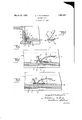
ftheinveiition;consists' in the liiovelffefatures ion asnore ullyhereinafter set j c f clined to thefiiange 2 fromy its point ofjuncf i vture with the shorter leg toits point of junoY 1 f Voconstruct 2 "QFfgure1`f1s'afc oss'section' through a bar of alxnetallic Window sash; showing the clip enbodying` my invention applied tothew'bar VFigure is an elevation of the showngin Figure `1;
ar and clip view,` showingv a f y,providedbetiveenltheilange and the pane and `forming aV seat orhthe) latter."I This bar has the Webi- Which extendstransversely l of vthe fronitheadj acent edge *oi thepaneB; v
^ The Clip ie, embayin'g my invention; is
formed ofresilientWire and has thelegs?` and 8'the` first of which is 4shorter than the` latter. These legs have at their outer ends the laterally bent portions 9, Whichare en-r gageablewith the apertures 10 formed in the Y web 5 'of the bar at substantially ythe same distance from the' flange 2. These legs*y also 345 have the innerA loop portions 11 with the loop portion' of the leg 7 of smaller radius than that of the leg 8,` The legs extend adjacent v tok the web 5 fand their loop portions extend v betweenthis'web rand the adjacent edge of n 50 the pane 3. The clip Valso comprisesjthe laterally bent abutrnent portion v12 havingA the transverse endsj13fConnecting'fintoy the legs Y 'and' the intermediatepart 13. The ends 113 With the legsf` and l@turned Ltoward thepane and the intermediate kpart 13 e engages ythe pane .toresilientlyforce the'rsaine towardfthe f z so that theintermed the pane.
- The abut ia'tep'art does not damage ment, portion-.V12 is -nornuallylv inv ture Withgthe longer leg lwhen the ,clipI isras-v are inclined from theirfpoints of juncture K' 6c 4lgages'the pane? at a .distance from lits-edge .Y y
sembled with the sashso'tbatthe portion'of'l v r the Aintermediate part 13( adjacent thelonger leg Ynormally 'engages the pane. The point of' ff vkjuncture between-this abutment portion and t the shorterleg 7 isin substantially the same plane extending transversely ofthe paneas Y the point'ofconnection betvveenthe laterally Y lbent outer endofthislegand the sash bar The point of juncturebetween this abutment portion andthe longer leg is, however,v oli# `set longitudinally of the sash bar roIn-the pointof-juncture offthe laterally bent end n' I of the longer leg and the sash bar. j With this" construction, any iiexing occurring in the clip occursmainly in the longer leg, the distance .between thepoint of juncturezpoi the abut'-k inent portion andthe shorter legyand the llatl eral-lygbent. outer". end ofl this shorter legy re-f maining substantially constant." cAsaf result,"
- Inpiaeingythe ciip-rinfpsitiomthelaterally 'bentv outer end 9of the'shorter le'gf'? i'slinsertthe-f clip vfulcruinsabout the laterally. bent 'f wouter, endjof thefslorter leg'pin ,additionvtoy so' f Ted` intd an `aperture in the web jo-thesash I `:bar land thefinne'r yloopportions offthe two l Y' Y legs entered betweenfthe web, f Land fthe ad- Ajacentf'yedgeof the; glass 13 by; swinging the fclip'rinwardlyffafter which the longer leg n is flexed to engage its laterally bent outer end in the other aperture of the sash bar web.
This operation may be suitably rcarried out asby means of a putty knife.
It will be seen that the construction is such that the Vclip is securely held in position by reason of its loo portions entering between the sash bar weg'and the adjacent edge of the glass. It will also be seen that this clip lo'secnrely holds the pane in positionfvan'd furthermore that it takes Careof panes of various i thicknesses. It willrbe further seen that the construction of clip is such that it can not be snapped into place, so that the corners of the ane cannot be chipped and that the clip bears upon the pane at a point laterally spaced from its edge yso that thepane is further protected from being damaged by the '2 What I claim as my inventionis:
Y .1. v'llhexcombination with a sash bar anda window pane, of a clip for securing said pane iiors'aid barv havinglegs with one extending betweensaid bar and the edge of said pane,
nid legs being provided nwithend portions en- ,gtgeahle with shoulders. on said bar, and an `:abutmentportion connecting said Ylegs and engaging said pane. v
4.r The combination 'with' a sash bar .an a y'Window pane, of a clip forsecuring said pane to saidbar having legs. of different ylength provided with endr portionsengageable with shoulders on said bar andan abutvment portion connecting said'legsand engaging sa1dpane,qthe point of juncture'of said abutment portion andthe leg of less length x"ing transversely of said pane..r f
5.' The combination with a sash'bar 'and i a window pane, of a clip for securing said clip to said bar having legs ofL different length and provided with end portions engwgeable with `shoulders on said bar, vone of said -legs extending between said bar and jacent'to thejuncture of sai latere f. portion lwith the leg of greater le ,the
in substantially the same plane extending transversely of said pane.
6. The combination with a sash bar and a Window pane, of a clip for securing said pane to said bar having legs provided with laterally bent youter ends exile with apertures in said'bar and with loop portions at their inner ends extending between said bar and the edge of said pane, and a laterally bent abutment ortion'connecting said le andengaging sai pane.
The combination with a sash bar and a rwindow pane, of a resilient wire clip for securing said panerto said bar having legs of di'erentlength provided with end rtions engageable with shoulders on said ar and a lateral abutment portion connecting said legs andengaging said pane adjacent to the juncture ofsaid abutment portion andthe leg'ofigreater length, said point offiunctuae .being oset longitudinally of lsaid from the point of connection of the legof greater length with said bar. f
8. The combination with a sash bar and :a window pane, of laresilient, wire clip for( securing said pane to saidv bar having les;
n ofvfdiierent length having laterallybenten engageable with kapertures .in said bar, one of said legs extending betweenisaid and said pane, and a laterally bent portion connecting said legs and kengagin said. anegdpoint of juncture of said laterally bentportion and the leg of greater length 0fyset longitudinally of :said bar from therpoint of connection of said leg with said buyand the point of juncture of said'laterally bent yportion and the leg of less length bem 4in substantially the same plane exten ing transversely of said pane. y
9. The combination-with a sash bar and ia `window pane, `of a clip for securing said pane to said bar having le kwith one extending between said bar an the edge of said panefsaid legs being provided with `transverse end portions engageable with shoulders on said bar, and an abutment ortion connecting said legs and engaging said pane ata point laterally spaced from its edge.l
In testimony whereof I aix m si ture.
JOSEPH N. MLo G t being in substantially thesame plane. extendv the edge of said pane,`and a lateral abutment d portion connecting said legs and engaging Y'saidpand the 'point of juncture of saidr abut- 'M -ment portion and the leg of less length being
Priority Applications (1)
| Application Number | Priority Date | Filing Date | Title |
|---|---|---|---|
| US453735A US1851201A (en) | 1930-05-19 | 1930-05-19 | Glazing clip |
Applications Claiming Priority (1)
| Application Number | Priority Date | Filing Date | Title |
|---|---|---|---|
| US453735A US1851201A (en) | 1930-05-19 | 1930-05-19 | Glazing clip |
Publications (1)
| Publication Number | Publication Date |
|---|---|
| US1851201A true US1851201A (en) | 1932-03-29 |
Family
ID=23801847
Family Applications (1)
| Application Number | Title | Priority Date | Filing Date |
|---|---|---|---|
| US453735A Expired - Lifetime US1851201A (en) | 1930-05-19 | 1930-05-19 | Glazing clip |
Country Status (1)
| Country | Link |
|---|---|
| US (1) | US1851201A (en) |
Cited By (6)
| Publication number | Priority date | Publication date | Assignee | Title |
|---|---|---|---|---|
| US2497515A (en) * | 1945-07-07 | 1950-02-14 | Libbey Owens Ford Glass Co | Glazing construction |
| US2614667A (en) * | 1949-06-18 | 1952-10-21 | Kirlin Company | Pane fastener |
| US2637423A (en) * | 1950-11-13 | 1953-05-05 | Gabriel Steel Company | Glazing clip |
| US2646863A (en) * | 1950-04-17 | 1953-07-28 | Admiral Corp | Fastener device |
| US4319420A (en) * | 1981-01-08 | 1982-03-16 | Clinton Robert E | Canvas frame spring tension wire clamp apparatus |
| FR2732064A1 (en) * | 1995-03-20 | 1996-09-27 | Norcan | Mounting joint for window or panel in frame |
-
1930
- 1930-05-19 US US453735A patent/US1851201A/en not_active Expired - Lifetime
Cited By (6)
| Publication number | Priority date | Publication date | Assignee | Title |
|---|---|---|---|---|
| US2497515A (en) * | 1945-07-07 | 1950-02-14 | Libbey Owens Ford Glass Co | Glazing construction |
| US2614667A (en) * | 1949-06-18 | 1952-10-21 | Kirlin Company | Pane fastener |
| US2646863A (en) * | 1950-04-17 | 1953-07-28 | Admiral Corp | Fastener device |
| US2637423A (en) * | 1950-11-13 | 1953-05-05 | Gabriel Steel Company | Glazing clip |
| US4319420A (en) * | 1981-01-08 | 1982-03-16 | Clinton Robert E | Canvas frame spring tension wire clamp apparatus |
| FR2732064A1 (en) * | 1995-03-20 | 1996-09-27 | Norcan | Mounting joint for window or panel in frame |
Similar Documents
| Publication | Publication Date | Title |
|---|---|---|
| US2216219A (en) | Clip | |
| US2093727A (en) | Insulating window | |
| US1851201A (en) | Glazing clip | |
| US2288329A (en) | Mounting or joint strip | |
| US1573194A (en) | Door | |
| US3848390A (en) | Window fastener | |
| US3430385A (en) | Unitary prehung door and frame | |
| US2105784A (en) | Window channel or the like | |
| US2682321A (en) | Channel strip coupling for lighting fixtures | |
| US1873485A (en) | Doorlock | |
| US2178507A (en) | Fitting for use with glazing bars | |
| US2342537A (en) | Corner fastener for metal frames | |
| US1355322A (en) | Flagpole-bracket | |
| US1725559A (en) | Window structure | |
| US2637423A (en) | Glazing clip | |
| US1688953A (en) | Window-glass clip | |
| US1278343A (en) | Corner-bar. | |
| US3394508A (en) | Roof joint | |
| US1820206A (en) | Fastening means for corner frame strips | |
| US1708068A (en) | Glazing clip | |
| US1139729A (en) | Shade-fixture. | |
| US2208610A (en) | Striker plate for door locks | |
| US2656574A (en) | Latching means for window meeting rails | |
| US2332190A (en) | Combination storm and screen door | |
| US2560765A (en) | Unitary venetian blind bracket construction |