US1851133A - Remote volume control - Google Patents
Remote volume control Download PDFInfo
- Publication number
- US1851133A US1851133A US520757A US52075731A US1851133A US 1851133 A US1851133 A US 1851133A US 520757 A US520757 A US 520757A US 52075731 A US52075731 A US 52075731A US 1851133 A US1851133 A US 1851133A
- Authority
- US
- United States
- Prior art keywords
- volume
- pawl
- control
- volume control
- ratchet
- Prior art date
- Legal status (The legal status is an assumption and is not a legal conclusion. Google has not performed a legal analysis and makes no representation as to the accuracy of the status listed.)
- Expired - Lifetime
Links
- 241000136406 Comones Species 0.000 description 1
- 239000004020 conductor Substances 0.000 description 1
- 230000008878 coupling Effects 0.000 description 1
- 238000010168 coupling process Methods 0.000 description 1
- 238000005859 coupling reaction Methods 0.000 description 1
- 238000004519 manufacturing process Methods 0.000 description 1
- 238000000034 method Methods 0.000 description 1
- 238000012986 modification Methods 0.000 description 1
- 230000004048 modification Effects 0.000 description 1
- 108010085990 projectin Proteins 0.000 description 1
- XXPDBLUZJRXNNZ-UHFFFAOYSA-N promethazine hydrochloride Chemical compound Cl.C1=CC=C2N(CC(C)N(C)C)C3=CC=CC=C3SC2=C1 XXPDBLUZJRXNNZ-UHFFFAOYSA-N 0.000 description 1
Images
Classifications
-
- H—ELECTRICITY
- H03—ELECTRONIC CIRCUITRY
- H03G—CONTROL OF AMPLIFICATION
- H03G1/00—Details of arrangements for controlling amplification
- H03G1/02—Remote control of amplification, tone or bandwidth
Definitions
- the present invention relates to a method of and apparatus for controlling the volume volume of the sound reproduced in a talking
- the projection booths are usually enclosed, and it is impractical for the projectionist to accurately determine the efiectiveness of the volume being emitted by the loudspeaking equipment. Therefore, it is usual to post an observer in the audience, which observer act; ing in conjunction with the projectionist by -means of suitable signals such as electric light circuits or annunciators, indirectly controls the volume.
- Such an arrangement has a considerable disadvantage in that'the projectionist must when signalled, leave his post of observation and turn to the amplifier con trol panel tomake the required adjustment of the volume control in accordance with the signals thus transmitted to him.
- a more particular object of this invention is to produce an apparatus to enable the volume to be directly controlled by the observer stationed in the audience.
- a further object of this invention isto produce a system which shall contribute to a more finished talking movie effect by a proper volume control arrangement.
- the spindle of the potentiometer used the, said shaft 11.
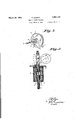
- Fig. 1 is a general view of the apparatus comprising my invention
- FIG. 2 is a projection showing the flexible connectionbetween the potentiometer shaft and the actuating ratchet, and;
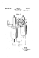
- Fig. 3 is a cross section of one of the solenoids of my invention, showing in detail one of the pawls and its actuating mechanism.
- the control mechanism comprises a pair of solenoids ee arranged to be actuated by suitable switches, as mentioned above, which, per se, constitutes no part of the present invention, and a ratchet and pawl Y mechanism for driving the said spindle a.
- a ratchet wheel I On the spindle a is mounted a ratchet wheel I), the periphery of which is formed with V- shaped teeth as'shown.
- the spindle is carried in bearing brackets a mounted on base plate d beneath which are mounted the sole-' noids H, on opposite sides of the center of the ratchet whee b.
- the solenoid e mounted in the core 0 the solenoid e is an armature f mounted on the armature rod 9.
- the rod 9 extends throu h the base plate d and has on its upper en a head h which is formed with inclined faces j and k.
- the head h is slidable in a guide tube m mounted on the u per side of the base plate d.
- a bifurcate block n mounted in the ide tube m, above the head h, is a bifurcate block n, the lower end of which has surfaces 0 and p correspondin in angle to the surfaces 7' and k respectively 0 the head 11.
- a pawl 9 formed with a tooth r and faces 8 and t corresponding with faces j and k, and o and p respectively.
- the tooth r of the pawl g is arranged so that when it is in the position shown, it will clear the teeth of the ratchet wheel I). However, when the block n is moved upward by means of the head It, the surfaces 7' and k of the head It will coact respectively with the faces a and t of the pawl g, and will rotate the pawl so that the tooth 1' will engage one of the V-shaped teeth on the ratchet b, as will be described more in detail hereinafter.
- the solenoids ee are connected through suitable conductors u and 'v with a switch 30 conveniently located in the hall or auditorium where the reproduction is taking place.
- the arrangement is such that when a switch 30 is closed in one direction, one of the solenoids ee becomes energized, and its armature f is raised. The first part of the upward movement of the armature f raises the head It until its faces 7' and k coact respectively with the corresponding faces .9 and t of the pawl g, and serve to tilt the pawl out so that the tooth 1- of the said awl will be brought under a tooth of the ratchet wheel 6. 7
- the ratchet wheel b and the spindle of the potentiometer are turned in one direction or the other to increase or decrease the volume of reproduction, it being understood that greater variation of volume is required than results from the closing of the solenoid circuit once, the potentiometer spin: dle may be moved step by step to the required extent by successive closin s of the circuit.
- the v0 ume of the sound reproduction is directly under the control of the observer, permitting the operator to attend to the projector portion of the apparatus.
- a friction pad may be provided upon the pawl, and the ratchet wheel may have a plain, a circumferentially grooved, or other suitable periphery.
- talking motion picture apparatus having picture projecting means, phonographic apparatus and an amplifier within a projection booth adjacent an auditorium, and having a picture projectin screen and sound reproducing means visi 1e and audible from said auditorium, means for controlling the volume of sound reproduction by controlling the amplifier from a point within the said auditorium comprising a variable resistance element constituting a portion of the said amplifier, means for rotating the control means of the said resistance element comprising a pair of solenoids, a pair of cores for the said solenoids, a pawl in cooperative relation with each of said cores and a ratchet wheel on the rotatable control member of-the said resistance adapted to be selectively rotated in either direction by the operation of one or the other of said pawls; and a pair of switches at the said point in the said auditorium connected to and adapted to operate the said solenoids, whereby an observer in the said auditorium ma rotate the said control memher in either direction to control the volume of sound produced by the said sound reproducer.
Landscapes
- Chair Legs, Seat Parts, And Backrests (AREA)
Description
March 29, 1932. SH|FFL REMOTE vommm CONTROL 2 Sheets-Sheet Filed March 6, 1931 INVENTOR FRANK SCHFFL BY ATTORNEY March 29, 1932. F' $cH|FFL 1,851,133
REMOTE VOLUME CONTROL Filed March 6, 1931 2 Sheets-Sheet 2 \NVENTOR FRANK SU-HFFL BY 4W ATTORNEY Patented Mar. 29, 1932 UNITED STATES PATENT OFFICE FRANK SGHIII'I'L, OI EAHPSTEAD, LONDON, ENGLAND, ASSIGNOB IO RADIO 'OOBPO- BATION OF AMERICA, 1 CORPORATION OF DELAWARE.
morn vommn comon Application fled March 8, 1881, Serial No. 520,757, and in Great Britain. January 8, 1880.
The present invention relates to a method of and apparatus for controlling the volume volume of the sound reproduced in a talking,
movie production from the projection booth. The projection booths are usually enclosed, and it is impractical for the projectionist to accurately determine the efiectiveness of the volume being emitted by the loudspeaking equipment. Therefore, it is usual to post an observer in the audience, which observer act; ing in conjunction with the projectionist by -means of suitable signals such as electric light circuits or annunciators, indirectly controls the volume. Such an arrangement has a considerable disadvantage in that'the projectionist must when signalled, leave his post of observation and turn to the amplifier con trol panel tomake the required adjustment of the volume control in accordance with the signals thus transmitted to him. Not only does this system require that .the projecting part of the apparatus be left unattended, but due not only to the personal equation but to the inherent time lag due to shifting attention from the projecting to the sound equipment, I the response to the observers signals is often not 'sufliciently rapid to be effective, and in deed frequently produces ludicrous results. The object of the present invention is to obviate these disadvantages.
A more particular object of this invention is to produce an apparatus to enable the volume to be directly controlled by the observer stationed in the audience.
A further object of this invention isto produce a system which shall contribute to a more finished talking movie effect by a proper volume control arrangement.
These and other objects of this invention will become apparent from the following specification taken in connection with the appended drawings.
In accomplishing the objects of my invention, the spindle of the potentiometer used the, said shaft 11.
to control the volume of the so'undreproducing amplifier is so'connected that it is adapted are adapted to actuate the pivotally mounted pawls, which in turn are adapted to co-act with the surface of a ratchet so disposed on a shaft as to control the turning of the potentiometer controlling the volume of the loudspeakers.
Having thus briefly described my invention, attention is invited to the accompanying figures in which;
Fig. 1 is a general view of the apparatus comprising my invention;
.Fig. 2 is a projection showing the flexible connectionbetween the potentiometer shaft and the actuating ratchet, and;
Fig. 3 is a cross section of one of the solenoids of my invention, showing in detail one of the pawls and its actuating mechanism.
Attention is particularly invited to the figures illustrating one form of my invention in which like parts are designated by like reference characters.
The spindle 11 of arheostat potentiometer, generally indicated at 13, connected in the amplifier circuit of the sound reproducing apparatus, is connected by means of the fiex-' ible coupling, Fig. 2) comprising a pin 15 mounted on a disc 17, which in turn is mounted on the ratchet spindle a of the control mechanism, coacting with a fork 21 secured to The control mechanism comprises a pair of solenoids ee arranged to be actuated by suitable switches, as mentioned above, which, per se, constitutes no part of the present invention, and a ratchet and pawl Y mechanism for driving the said spindle a. On the spindle a is mounted a ratchet wheel I), the periphery of which is formed with V- shaped teeth as'shown. The spindle is carried in bearing brackets a mounted on base plate d beneath which are mounted the sole-' noids H, on opposite sides of the center of the ratchet whee b.
Referring now more articularly to Fig. 3, mounted in the core 0 the solenoid e is an armature f mounted on the armature rod 9. The rod 9 extends throu h the base plate d and has on its upper en a head h which is formed with inclined faces j and k. The head h is slidable in a guide tube m mounted on the u per side of the base plate d. Also slida 1y mounted in the ide tube m, above the head h, is a bifurcate block n, the lower end of which has surfaces 0 and p correspondin in angle to the surfaces 7' and k respectively 0 the head 11.. Between the limbs of the bifurcated block is pivoted a pawl 9 formed with a tooth r and faces 8 and t corresponding with faces j and k, and o and p respectively.
The tooth r of the pawl g is arranged so that when it is in the position shown, it will clear the teeth of the ratchet wheel I). However, when the block n is moved upward by means of the head It, the surfaces 7' and k of the head It will coact respectively with the faces a and t of the pawl g, and will rotate the pawl so that the tooth 1' will engage one of the V-shaped teeth on the ratchet b, as will be described more in detail hereinafter.
The solenoids ee are connected through suitable conductors u and 'v with a switch 30 conveniently located in the hall or auditorium where the reproduction is taking place. The arrangement is such that when a switch 30 is closed in one direction, one of the solenoids ee becomes energized, and its armature f is raised. The first part of the upward movement of the armature f raises the head It until its faces 7' and k coact respectively with the corresponding faces .9 and t of the pawl g, and serve to tilt the pawl out so that the tooth 1- of the said awl will be brought under a tooth of the ratchet wheel 6. 7
Further movement upward of the armature f will raise the block n, and the tooth r will cause the ratchet to rotate until the upward movement of the block n is limited by means of the adjustable stop 'w at the top of .the tube m. When the circuit of the solenoid is broken, the armature f, rod g, head It, block n, and pawl 9 will return to their normal positions leaving the ratchet wheel in the angular position to which it has been moved.
Hence, by operating one or the other of a pair of switches, the ratchet wheel b and the spindle of the potentiometer are turned in one direction or the other to increase or decrease the volume of reproduction, it being understood that greater variation of volume is required than results from the closing of the solenoid circuit once, the potentiometer spin: dle may be moved step by step to the required extent by successive closin s of the circuit.
In this manner, the v0 ume of the sound reproduction is directly under the control of the observer, permitting the operator to attend to the projector portion of the apparatus.
It is obvious that instead of the tooth ratchet wheel shown, a friction pad may be provided upon the pawl, and the ratchet wheel may have a plain, a circumferentially grooved, or other suitable periphery.
Having thus described one embodlment of my invention it is to be understood that various modifications may be made therein, and that I am therefore not to be limited to the s cific embodiment shown and described for t e purpose of illustrationonly, but by the actual scope of my invention as set forth and determined in the appended claim.
I claim:
In talking motion picture apparatus having picture projecting means, phonographic apparatus and an amplifier within a projection booth adjacent an auditorium, and having a picture projectin screen and sound reproducing means visi 1e and audible from said auditorium, means for controlling the volume of sound reproduction by controlling the amplifier from a point within the said auditorium comprising a variable resistance element constituting a portion of the said amplifier, means for rotating the control means of the said resistance element comprising a pair of solenoids, a pair of cores for the said solenoids, a pawl in cooperative relation with each of said cores and a ratchet wheel on the rotatable control member of-the said resistance adapted to be selectively rotated in either direction by the operation of one or the other of said pawls; and a pair of switches at the said point in the said auditorium connected to and adapted to operate the said solenoids, whereby an observer in the said auditorium ma rotate the said control memher in either direction to control the volume of sound produced by the said sound reproducer.
FRANK SGHIFFL.
Applications Claiming Priority (1)
| Application Number | Priority Date | Filing Date | Title |
|---|---|---|---|
| GB1851133X | 1930-01-08 |
Publications (1)
| Publication Number | Publication Date |
|---|---|
| US1851133A true US1851133A (en) | 1932-03-29 |
Family
ID=10891964
Family Applications (1)
| Application Number | Title | Priority Date | Filing Date |
|---|---|---|---|
| US520757A Expired - Lifetime US1851133A (en) | 1930-01-08 | 1931-03-06 | Remote volume control |
Country Status (1)
| Country | Link |
|---|---|
| US (1) | US1851133A (en) |
-
1931
- 1931-03-06 US US520757A patent/US1851133A/en not_active Expired - Lifetime
Similar Documents
| Publication | Publication Date | Title |
|---|---|---|
| US1909765A (en) | Sound control method and means for practicing same | |
| US1851133A (en) | Remote volume control | |
| US2031605A (en) | Record and method of making and using same | |
| US2096020A (en) | Method of making a record | |
| US2962547A (en) | Position control of television images | |
| GB342284A (en) | Improvements in sonorous or kinematograph films | |
| US1788808A (en) | Motion-picture apparatus | |
| US2932235A (en) | Synchronized picture film and sound record apparatus | |
| US1124580A (en) | Method of and means for localizing sound reproduction. | |
| US3199404A (en) | Method and apparatus for automatically and repetitively making copies of preselectedportions of motion picture films | |
| US3305240A (en) | Magnetic tape dictating machine control | |
| US2676272A (en) | Sound and picture changeover system | |
| US2886649A (en) | Motion picture projector changing-over system for magnetic and optical scanning | |
| US2082745A (en) | Distant volume control | |
| US1970064A (en) | Remote volume control for talking and/or sound picture equipment | |
| US2182823A (en) | Sound film system | |
| US3675173A (en) | Presetting device for electronic musical instrument | |
| US1796970A (en) | Change-over for picture and sound projecting apparatus | |
| US2036306A (en) | Means for the change-over control of moving picture apparatus | |
| US2184565A (en) | Sound picture apparatus | |
| US3774131A (en) | Operating mode switching device | |
| US1836206A (en) | Method and apparatus for use in connection with the making of sound records | |
| US1283734A (en) | Remote control device. | |
| US3202044A (en) | Picture projecting system with remote portable control | |
| US1812449A (en) | Synchronized sound and photography |