US1850118A - Building construction - Google Patents
Building construction Download PDFInfo
- Publication number
- US1850118A US1850118A US312482A US31248228A US1850118A US 1850118 A US1850118 A US 1850118A US 312482 A US312482 A US 312482A US 31248228 A US31248228 A US 31248228A US 1850118 A US1850118 A US 1850118A
- Authority
- US
- United States
- Prior art keywords
- openings
- channel
- channels
- series
- sections
- Prior art date
- Legal status (The legal status is an assumption and is not a legal conclusion. Google has not performed a legal analysis and makes no representation as to the accuracy of the status listed.)
- Expired - Lifetime
Links
Images

Classifications
-
- E—FIXED CONSTRUCTIONS
- E04—BUILDING
- E04B—GENERAL BUILDING CONSTRUCTIONS; WALLS, e.g. PARTITIONS; ROOFS; FLOORS; CEILINGS; INSULATION OR OTHER PROTECTION OF BUILDINGS
- E04B1/00—Constructions in general; Structures which are not restricted either to walls, e.g. partitions, or floors or ceilings or roofs
- E04B1/18—Structures comprising elongated load-supporting parts, e.g. columns, girders, skeletons
- E04B1/24—Structures comprising elongated load-supporting parts, e.g. columns, girders, skeletons the supporting parts consisting of metal
- E04B1/2403—Connection details of the elongated load-supporting parts
- E04B2001/2415—Brackets, gussets, joining plates
-
- E—FIXED CONSTRUCTIONS
- E04—BUILDING
- E04B—GENERAL BUILDING CONSTRUCTIONS; WALLS, e.g. PARTITIONS; ROOFS; FLOORS; CEILINGS; INSULATION OR OTHER PROTECTION OF BUILDINGS
- E04B1/00—Constructions in general; Structures which are not restricted either to walls, e.g. partitions, or floors or ceilings or roofs
- E04B1/18—Structures comprising elongated load-supporting parts, e.g. columns, girders, skeletons
- E04B1/24—Structures comprising elongated load-supporting parts, e.g. columns, girders, skeletons the supporting parts consisting of metal
- E04B1/2403—Connection details of the elongated load-supporting parts
- E04B2001/2448—Connections between open section profiles
-
- E—FIXED CONSTRUCTIONS
- E04—BUILDING
- E04B—GENERAL BUILDING CONSTRUCTIONS; WALLS, e.g. PARTITIONS; ROOFS; FLOORS; CEILINGS; INSULATION OR OTHER PROTECTION OF BUILDINGS
- E04B1/00—Constructions in general; Structures which are not restricted either to walls, e.g. partitions, or floors or ceilings or roofs
- E04B1/18—Structures comprising elongated load-supporting parts, e.g. columns, girders, skeletons
- E04B1/24—Structures comprising elongated load-supporting parts, e.g. columns, girders, skeletons the supporting parts consisting of metal
- E04B2001/2466—Details of the elongated load-supporting parts
- E04B2001/2469—Profile with an array of connection holes
-
- E—FIXED CONSTRUCTIONS
- E04—BUILDING
- E04B—GENERAL BUILDING CONSTRUCTIONS; WALLS, e.g. PARTITIONS; ROOFS; FLOORS; CEILINGS; INSULATION OR OTHER PROTECTION OF BUILDINGS
- E04B1/00—Constructions in general; Structures which are not restricted either to walls, e.g. partitions, or floors or ceilings or roofs
- E04B1/18—Structures comprising elongated load-supporting parts, e.g. columns, girders, skeletons
- E04B1/24—Structures comprising elongated load-supporting parts, e.g. columns, girders, skeletons the supporting parts consisting of metal
- E04B2001/2466—Details of the elongated load-supporting parts
- E04B2001/2472—Elongated load-supporting part formed from a number of parallel profiles
-
- E—FIXED CONSTRUCTIONS
- E04—BUILDING
- E04B—GENERAL BUILDING CONSTRUCTIONS; WALLS, e.g. PARTITIONS; ROOFS; FLOORS; CEILINGS; INSULATION OR OTHER PROTECTION OF BUILDINGS
- E04B1/00—Constructions in general; Structures which are not restricted either to walls, e.g. partitions, or floors or ceilings or roofs
- E04B1/18—Structures comprising elongated load-supporting parts, e.g. columns, girders, skeletons
- E04B1/24—Structures comprising elongated load-supporting parts, e.g. columns, girders, skeletons the supporting parts consisting of metal
- E04B2001/2484—Details of floor panels or slabs
-
- E—FIXED CONSTRUCTIONS
- E04—BUILDING
- E04B—GENERAL BUILDING CONSTRUCTIONS; WALLS, e.g. PARTITIONS; ROOFS; FLOORS; CEILINGS; INSULATION OR OTHER PROTECTION OF BUILDINGS
- E04B1/00—Constructions in general; Structures which are not restricted either to walls, e.g. partitions, or floors or ceilings or roofs
- E04B1/18—Structures comprising elongated load-supporting parts, e.g. columns, girders, skeletons
- E04B1/24—Structures comprising elongated load-supporting parts, e.g. columns, girders, skeletons the supporting parts consisting of metal
- E04B2001/2496—Shear bracing therefor
Definitions
- My invention relates to steel structures and more particularly to structural steel sections and methods for fabricating and erecting the same, the principal object ofv the invention being to adapt steel for use in the construction of relatively small buildings.
- Structural steel has heretofore been provided in shapes, weights and condition for the frames of relatively large holdings, and for bridges; and relatively light steel sections such as angles have been provided for miscellaneous framing and reinforcing purposes.
- the use of standard sections for smaller buildings such as dwellings involves the installation of anexcessive amount of steel proportionate to the duty of the frame work, and the use of the lighter standard members such as angles requires make-shift means for building up studs and beam members therefrom and a multiplicity of connectors for tying the structural members together.
- standard rolled sections such as I-beams are used in frame-works chiefly consisting of light standard. steel members, since the angles and channels now available are not adapted for building up structural sections to replace the rolled beams.
- Further objects of the invention are to minimize the amountof sho drawings necessary for the preparation of t e steel material for a buildlng, to minimize the sho work for conditioning steel sections carried in stock, to 1 simplify the gathering of the steel materials for a building, and to reducethe labor ins volved in the erection of a steel frame-work while assuring accuracy of assembly. and rigidity and strength of the structure.
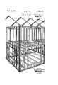
- Fig. 1 is a perspective view of adjacent front and side portions of a steel framework embodying my invention.
- Fig. 2 is avertical sectional view of a cor-- ner portion of a completed building including portions of the steel frame-work viewed from the side in Fig. 1.
- Fig. 3 is a cross section of a sill on the line 3 3, Fig. 1.
- Fig. 4 is across section of a corner stud or colunm on the line 44, Fig. 1.
- Fig. 5 is an enlarged perspective view of a clip angle for connecting angularly extendin members.
- ig. 6 is a fragmentary elevational view of a connected sill and stud shown on the line 6-6, Fig. 1.
- Fig. 7 is an enlarged perspective view of adjacent end portions of characteristic structural steel members constructed in accordance with my invention and adapted to be joined to form beam-like sections.
- the basic elements in the structure are structural steel sections. or members such as r 11 and 12 which are channel-like and will therefore be identified as channels in the description to distinguish them from beam-like structural members andsections built up of channels either in the yard or on the job.
- the channel such as 11, Fig. 7, comprises a web or body 13 and like flanges 14 which may vary in width from the width of the web, the
- the '- web having a longitudinal series of uniformly spaced openings 15 on its median line and each of the flanges having a'series of similarly spaced openings 15 approximately on its median line, but spaced from the back edges of the flanges the same distance as the spacing of the web openings from the longitudinal edges of the outer surface or back 13 of the web, the openings of the flanges being traisversely aligned with the openings of the we The openings. are spaced from the end edges of the web and flanges by a distance equal to half of the spacing between the openings in a series from center to center, and the spacing of the openings from the end edges is equal to the spacing of the openings from the outer common longitudinal edges of the flanges and web.
- the channel 12 comprises a web 16 the width of which represents a multiple of the width of the web 13 and is preferably twice I the width of said web 13, and equal flanges 17 each provided with a series of openings 18 similarl uniformly speaced and similarly dispose to the openings 15 in the flanges of the channel 11.
- the web 16 of the channel 12 is provided with a plurality of Ion itudinal series of openings 19 and 20 space from the lon itudinal edges of the back 16 of the web y a distance equal to the spacing of the openings 15 and 18 from the edges of the portions in which they are formed.
- the openings 19 and 20 are also transversely aligned with the openings 18 in the flanges 17 of said member 12, whereby registry of an end or back edge of one channel with an end or back edge of another channel will result in registry of openings for insertion of bolts for connecting the channels.
- I preferably fabricate the channels described, from a steel strip, rolling the strip to provide a fiat plate of indefinite length,
- One type is represented by the channel 11 which has three openings in each lateral series, the central opening being on the median line of the web when the strip has been formed to produce the channel.
- the type 12 has preferably four openings in each transverse series whereby two longitudinal series of openings are provided in the web.
- a beam member such as the sill 1 (Fig. 3) comprises a channel 11 and a channel 12 positioned with one of its flanges 17 aligned with the web of the channel 11 and the lower portion of its web in back to face contact with the adjacent flange 14: of the channel 11, the series of openings 20 of the channel 12 registering with the openings of the flange of the member 11 to receive bolts 21 for securely connecting the members.
- Studs such as the amb studs 5 and intermediate studs 6 consist of channels 11 positioned vertically on the channel 11 of a ground floor sill 1 or 2 with the sides of their lower ends engaging the upwardly extending portion of the web of the channel 12.
- Supporting upper floor sills such as 3 and 4 are reversely positioned to the lower sills so that the channels 11 of the upper sills rest on the upper ends of the studs and depending portions of the channels 12 engage the sides of the studs.
- the stiffer studs 7 comprising posts or columns for the corners and similar positions in the frame are preferably constructed of three channel members 11a, 11b, and 110 as illustrated in Fig. 4, two of the channel mem bers having their webs in back to back contact while the web of the third is in back to face contact'with the flange of one of the first named channels, the engaged channels being connected by bolts.
- the end of one channel may extend beond the end of the mating channel in a cam as illustrated in Fig. 6 and shown in Fig. 1 at the points Where the sills meet and are connected with the corner studs, for example the end of the channel 12 of the side ground sill 2 being spaced from the end of the channel 11 of said member to receive the channels 12 and 11 of the sill l and permit the mounting of the channels 11a and 11b of the corner stud on the channel 11 of the sill 2 and the mounting of the channel 110 of the corner stud on the channel 11 of the sill 1, a similar interlocking or dove-tailed arrangement being rovided for kaulning the upper end of a stu with upper s1 s.
- brackets or clip angles 22 comprising rightangularly extending arms 23 and 2 1 having a series of aligned openings 25 uniformly spaced similarlyto the longitudinal spacing of the channel openings.
- the clips may be mounted at the juncture of right-angularly extending members, either within the recesses of the channels or on the outer, faces of the channels, and because of the uniform and. similar spacing of the openings of the clips and channels, the o enings will be in registry to receive bolts or attaching one arm of the clip to one channel and the other arm to an angularly extending channel to secure the stud to a sillas illustrated particularly in Fig. 6, or to secure a lintel to a jamb as illustrated in Fig. 1.
- the jambs 5, intermediate studs 6 and short studs 10 may also be connected to sills by clip angleslying in the recesses of the channels or extending along the faces thereof since the uniform spacing of the openings of both clip angles and channels longitudinally and from the end edges of the respective members assures registry of openings to receive connecting bolts.
- tie-rods 26 comprising relatively flexible rods having ends threaded to a distance equal to the longitudinal spacing of the openings in a channel, whereby one end of a rod may be secured to one channel by suitable fastening means such as a nut, extended through a selected opening in an intermediate stud and into an available opening of another channel for latching to the last named channel with a suitable fastener such as a nut.
- the uniform longitudinal spacing of the openings in the studs and sills permits any desired extension of the tie-rods over an extremely wide range since an opening is always available within the distance of a unit of spacing of the openings to receive the outer threaded end of the rod, and the rods 1 need not be extended rectilinearly.
- Floor beams such as 27 and 28 may be positioned in engagement with the lower and upper sills for support therefrom, and ceiling sills may support angularly extending rafters 29 comprising channels 12, the upper ends of which at the ridge of the roof are connected by single bolts extending through the terminal openings in the channels.
- the rafters are latched to the upper ceiling sills by clip angles each having one arm bolted to the sills and an upwardly extending arm bolted to the web of the rafter channel.
- Building materials such as wooden beams 30 may be bolted to the flanges or bodies of the channels and the openings provide convenient means for securing wall covering such as 31 and floor materials 32 to the structural sections.
- a stock of steel strips is first provided in sets, each set including strips of two widths, one width being adapted to form the channels 11 and the other to form the channels 12. For example, strips approximately 9 inches wide will be provided for the channels 11 and strips approximately 12 inches wide for the channels 12; or strips 12 inches wide for the channels 11 and 16 inches wide for the channels 12.
- the strips are first straightened and then the openin s are punched.
- the longitudinal spacing of the openings from center to center is substantially equal to one-third the width of the strip, the outer longitudinal series being spaced equally from the positions of the common longitudinal edges of the web and flanges and a distance equal to half the longitudinal spacing of the openings.
- the central longitudinal series of openings in the strip adapted for channels 11 is on the median line of the strip.
- the two interior longitudinal series on the strips adapted for channels 12 are spaced from center to center equally with the longitudinal spacing and equally distant from the median line of the strip.
- the strips are bent into channel shape whereby the end edge or one back edge of one channel may be positioned in registry with the end or back edge of another channel and there will be assurance of registry of openings for connecting the channels.
- the channels arethen selected in accordance with'the tabulation, and cut and assembled without the necessity for shop drawings. No other operations are involved than cutting the channels and bolting the members of a section together. The bolting maybe performed on the job. In any event relatively light members in condition for erection are transported to the site of the building and a relatively small number of types of sections is necessary since jambs and intermediate studs, lintels and opening sills,rshort studs for various positions, and sills for front and sides and for upper stories, are respectively interchangeable.
- the tie rods and clip angles are all of uniform type and size since they are adapted to be applied to openings which are uniformly spaced in all the members.
- a structural steel beam comprising a channel-like section having longitudinal :imseries of centrally disposed openings in its body and flanges and a second channel-like, section having a body gagement with the body of the first named channel and provided with a plurality of.
- a structural steel beam comprising a channel-like section having longitudinally centrally disposed openings in its body and flanges and a second channel-like sect on having a body provided with a plurality of longitudinal series of openings spaced similarly to'the openings of the first named channel and spaced from the longitudinaledges of the body equally with the spacing of the openings-of said first channel from the longitudinal edges thereof, a flange of the first named section being in face to back engagement with the body of the second-named section.
- a structural steel beam comprising a plurality of members including a channellike section having longitudinally disposed equally spaced openings on the center lines of J; its body and flanges and a second channel-like section having body in back to face engagement with.
- a flange of the first named ,ehannel and provided with a plurality of longitudinal series of openings spaced simi larly to the openings of the first named channel and spaced from the longitudinal edges of the body equally with the spacing-of the openings of said first channel from the longitudinal edges thereof, means in said openings securing the channels together, said secin back-to back en-' 0nd channel having equal flanges provided with uniformly s aced openings registerable with openings 0 similar channels for connection therewith.
- a beam comprising a channel-like memberv comprising a body and equal flanges of equal width with the body, said body and flanges having longitudinal series of openings uniformly spaced from center to center by a distance equal to the width of the body and a second channel-like member com rising a web having twice the width of said ody and a (plurality of series of longitudinally arrange openings spaced similarly to the spaced openings of the first named member whereby an abutting flange of the first named member may engage the web of the second named member for registry of openings of said web and flange.
- a beam comprising a channel-like member comprising a body and equal flanges of equal width with the body, said body and flanges having longitudinal series of openings uniformly spaced from center to center by a distance equal to the width of the body and a second channel-like member comprising a web having twice the width of said body and having a plurality of series of longitudinally arranged opemngs uniformly spaced similarly to the spaced openings of the first named member, the second'channel member having equal flanges provided with longitudinal series of opemngs spaced similarly to the openings of the first named member.
- A'beam comprising a channel-like member comprising a body and equal flanges of equal width with the body, said body and flanges having longitudinal series of openings on their median lines spaced from cen-' ter to center by a distance equal to the width of the body and flanges, and a second channeLlike member comprising abody having a plurality of series of longitudinally arranged openings'spaced similarly to the spaced openings o the said first named member, and flanges provided with longitudinal series of openings spaced similarly to the openings of the first named member, a selected series of openings in the flange of one member registering with a selected series of openings of the other member, and fastening means in registering openings.
- verticalv members including channel-like sections, a transverse member comprising a channel-like section, said members having similarly and uniformly spaced series of longitudinally arranged web openings, and a bracket comprising angular. arms having a series of longitudinally arranged openings spaced similarly to the spacing of aforesaid openings for registry therewith to receive bolts adapted to connect the arms of the bracket-with the vertical and transverse members respectively for support of the transverse member from the vertical members.
- a steel structure comprising spaced vertical channel-like sections having longitudinal series of regularly spaced openings, horizontal channel-like sections having series of openings spaced similarly to those of the vertical sections, means including members insertable in selected openings for connecting the vertical sections with the horizontal sections, and tie rods adapted to be mounted in selected 0 enings of said sections to receive nuts a apted to anchor the tie rods in functional position to brace the structure.
- a series of vertical channel-like sections having longitudinal series of uniformly spaced openings, transverse sections having series of openings similar to those of the vertical sections, means for connecting the sections, and tie rods movable through selected openings, and nuts adapted to anchor said rods to selected sections in tieing position.
- a beam including channels having right angular web and flange portions provided with longitudinal series of openings spaced equally from longitudinal edges of the portions, one portion of one channel being in face to face engagement with one portion of the other channel and the openings in said portions registering to receive fastening means, andthe adjacent right angular portion of the first named channel being in alignment with the adjacent right angular portion of the second named channel.
Description
March 22, 1932. MEYERS 1,850,118
BUILDING CONSTRUCTION Filed Oc t. 15, 1928 2 Sheets-Sheet 1 ATTORNEY March 22, 1932. A. M. MEYERS BUILDING CONSTRUCTION Filed Oct. 15, 1928 ZSheetS-Sheet 2 V -INVENTOR /gf/v M-Meye/a ATTORNEY l I l I l I u I I 4 vll Patented Mar. 22, 1932 UNITED STATES ALFRED I. MEY'ERS, OF KANSAS CITY, KANSAS BUILDING CONSTRUCTION Application filed October 15, 1928. Serial 1T0. 312,482.
My invention relates to steel structures and more particularly to structural steel sections and methods for fabricating and erecting the same, the principal object ofv the invention being to adapt steel for use in the construction of relatively small buildings.
Structural steel has heretofore been provided in shapes, weights and condition for the frames of relatively large holdings, and for bridges; and relatively light steel sections such as angles have been provided for miscellaneous framing and reinforcing purposes. The use of standard sections for smaller buildings such as dwellings involves the installation of anexcessive amount of steel proportionate to the duty of the frame work, and the use of the lighter standard members such as angles requires make-shift means for building up studs and beam members therefrom and a multiplicity of connectors for tying the structural members together.
Furthermore, standard rolled sections such as I-beams are used in frame-works chiefly consisting of light standard. steel members, since the angles and channels now available are not adapted for building up structural sections to replace the rolled beams.
It is therefore a further object of the invention toshape and'fabricate a structural steel section for use in the erection of small buildings and to build up structural steel sections from such novel members, whereby the amount of steel used in a building will be exactly proportionate to the duty of the frame-work, and the connected sections will adequately support the structure.
Further objects of the invention are to minimize the amountof sho drawings necessary for the preparation of t e steel material for a buildlng, to minimize the sho work for conditioning steel sections carried in stock, to 1 simplify the gathering of the steel materials for a building, and to reducethe labor ins volved in the erection of a steel frame-work while assuring accuracy of assembly. and rigidity and strength of the structure.
In accomplishin these and other objects of the invention, have provided improved details of structure, the preferred forms of which are, illustrated in the accompanying drawings, wherein:
Fig. 1 is a perspective view of adjacent front and side portions of a steel framework embodying my invention.
Fig. 2 is avertical sectional view of a cor-- ner portion of a completed building including portions of the steel frame-work viewed from the side in Fig. 1.
Fig. 3 is a cross section of a sill on the line 3 3, Fig. 1.
Fig. 4 is across section of a corner stud or colunm on the line 44, Fig. 1.
Fig. 5 is an enlarged perspective view of a clip angle for connecting angularly extendin members.
ig. 6 is a fragmentary elevational view of a connected sill and stud shown on the line 6-6, Fig. 1.
Fig. 7 is an enlarged perspective view of adjacent end portions of characteristic structural steel members constructed in accordance with my invention and adapted to be joined to form beam-like sections.
' Referring in detail to the drawings:
1 and 2 desi nate front and side ground floor, sills 3 and 4 upper floor sills, 5, 6, and
..7, studs for supporting the upper from the lower sills, 8 sills of building openings, 9 the lintels for said openings and 10 short studs for connecting the transverse members with the sills, all being constructed in accordance with my invention as presently described and comprisin steel frame elements in a two story bui ding to which the invention is shown as applied for illustrative purposes.
The basic elements in the structure are structural steel sections. or members such as r 11 and 12 which are channel-like and will therefore be identified as channels in the description to distinguish them from beam-like structural members andsections built up of channels either in the yard or on the job.
The channel such as 11, Fig. 7, comprises a web or body 13 and like flanges 14 which may vary in width from the width of the web, the
'- web having a longitudinal series of uniformly spaced openings 15 on its median line and each of the flanges having a'series of similarly spaced openings 15 approximately on its median line, but spaced from the back edges of the flanges the same distance as the spacing of the web openings from the longitudinal edges of the outer surface or back 13 of the web, the openings of the flanges being traisversely aligned with the openings of the we The openings. are spaced from the end edges of the web and flanges by a distance equal to half of the spacing between the openings in a series from center to center, and the spacing of the openings from the end edges is equal to the spacing of the openings from the outer common longitudinal edges of the flanges and web.
The channel 12 comprises a web 16 the width of which represents a multiple of the width of the web 13 and is preferably twice I the width of said web 13, and equal flanges 17 each provided with a series of openings 18 similarl uniformly speaced and similarly dispose to the openings 15 in the flanges of the channel 11.
The web 16 of the channel 12 is provided with a plurality of Ion itudinal series of openings 19 and 20 space from the lon itudinal edges of the back 16 of the web y a distance equal to the spacing of the openings 15 and 18 from the edges of the portions in which they are formed. The openings 19 and 20 are also transversely aligned with the openings 18 in the flanges 17 of said member 12, whereby registry of an end or back edge of one channel with an end or back edge of another channel will result in registry of openings for insertion of bolts for connecting the channels.
Attention is now called to characteristics of standard channels which hamper their use punched by a fabricator according to specifications for a particular job.
I preferably fabricate the channels described, from a steel strip, rolling the strip to provide a fiat plate of indefinite length,
punching successive lateral series of openmgs to rm parallel longitudinal series of openings in the fiat strip, and bending the stri on longitudinal lines positioned central y between the outer series and the adlacent series of longitudinally disposed openings to form a channel-like section, which may be cut' into lengths suitable for aparticular job.
Two types of channels may be produced,
tion with the dimensions of the member 12 though the dimensions may vary. One type is represented by the channel 11 which has three openings in each lateral series, the central opening being on the median line of the web when the strip has been formed to produce the channel. The type 12 has preferably four openings in each transverse series whereby two longitudinal series of openings are provided in the web.
A beam member such as the sill 1 (Fig. 3) comprises a channel 11 and a channel 12 positioned with one of its flanges 17 aligned with the web of the channel 11 and the lower portion of its web in back to face contact with the adjacent flange 14: of the channel 11, the series of openings 20 of the channel 12 registering with the openings of the flange of the member 11 to receive bolts 21 for securely connecting the members.
Studs such as the amb studs 5 and intermediate studs 6 consist of channels 11 positioned vertically on the channel 11 of a ground floor sill 1 or 2 with the sides of their lower ends engaging the upwardly extending portion of the web of the channel 12. Supporting upper floor sills such as 3 and 4 are reversely positioned to the lower sills so that the channels 11 of the upper sills rest on the upper ends of the studs and depending portions of the channels 12 engage the sides of the studs.
The stiffer studs 7 comprising posts or columns for the corners and similar positions in the frame are preferably constructed of three channel members 11a, 11b, and 110 as illustrated in Fig. 4, two of the channel mem bers having their webs in back to back contact while the web of the third is in back to face contact'with the flange of one of the first named channels, the engaged channels being connected by bolts.
The end of one channel may extend beond the end of the mating channel in a cam as illustrated in Fig. 6 and shown in Fig. 1 at the points Where the sills meet and are connected with the corner studs, for example the end of the channel 12 of the side ground sill 2 being spaced from the end of the channel 11 of said member to receive the channels 12 and 11 of the sill l and permit the mounting of the channels 11a and 11b of the corner stud on the channel 11 of the sill 2 and the mounting of the channel 110 of the corner stud on the channel 11 of the sill 1, a similar interlocking or dove-tailed arrangement being rovided for jolilning the upper end of a stu with upper s1 s.
The channels of the several beams are further connected and secured together by brackets or clip angles 22 comprising rightangularly extending arms 23 and 2 1 having a series of aligned openings 25 uniformly spaced similarlyto the longitudinal spacing of the channel openings. The clips may be mounted at the juncture of right-angularly extending members, either within the recesses of the channels or on the outer, faces of the channels, and because of the uniform and. similar spacing of the openings of the clips and channels, the o enings will be in registry to receive bolts or attaching one arm of the clip to one channel and the other arm to an angularly extending channel to secure the stud to a sillas illustrated particularly in Fig. 6, or to secure a lintel to a jamb as illustrated in Fig. 1.
The jambs 5, intermediate studs 6 and short studs 10 may also be connected to sills by clip angleslying in the recesses of the channels or extending along the faces thereof since the uniform spacing of the openings of both clip angles and channels longitudinally and from the end edges of the respective members assures registry of openings to receive connecting bolts.
Portions of the frame comprisingthe studs and sills are braced and stiflened by tie-rods 26 comprising relatively flexible rods having ends threaded to a distance equal to the longitudinal spacing of the openings in a channel, whereby one end of a rod may be secured to one channel by suitable fastening means such as a nut, extended through a selected opening in an intermediate stud and into an available opening of another channel for latching to the last named channel with a suitable fastener such as a nut.
The uniform longitudinal spacing of the openings in the studs and sills permits any desired extension of the tie-rods over an extremely wide range since an opening is always available within the distance of a unit of spacing of the openings to receive the outer threaded end of the rod, and the rods 1 need not be extended rectilinearly.
Floor beams such as 27 and 28 may be positioned in engagement with the lower and upper sills for support therefrom, and ceiling sills may support angularly extending rafters 29 comprising channels 12, the upper ends of which at the ridge of the roof are connected by single bolts extending through the terminal openings in the channels.
The rafters are latched to the upper ceiling sills by clip angles each having one arm bolted to the sills and an upwardly extending arm bolted to the web of the rafter channel.
Building materials such as wooden beams 30 may be bolted to the flanges or bodies of the channels and the openings provide convenient means for securing wall covering such as 31 and floor materials 32 to the structural sections.
In employing the invention a stock of steel strips is first provided in sets, each set including strips of two widths, one width being adapted to form the channels 11 and the other to form the channels 12. For example, strips approximately 9 inches wide will be provided for the channels 11 and strips approximately 12 inches wide for the channels 12; or strips 12 inches wide for the channels 11 and 16 inches wide for the channels 12. When provided in coil form the strips are first straightened and then the openin s are punched. In punching the strip to orm a channel 11, the longitudinal spacing of the openings from center to center is substantially equal to one-third the width of the strip, the outer longitudinal series being spaced equally from the positions of the common longitudinal edges of the web and flanges and a distance equal to half the longitudinal spacing of the openings.
The central longitudinal series of openings in the strip adapted for channels 11 is on the median line of the strip. The two interior longitudinal series on the strips adapted for channels 12 are spaced from center to center equally with the longitudinal spacing and equally distant from the median line of the strip.
After the openings are punched the strips are bent into channel shape whereby the end edge or one back edge of one channel may be positioned in registry with the end or back edge of another channel and there will be assurance of registry of openings for connecting the channels.
The channels arethen selected in accordance with'the tabulation, and cut and assembled without the necessity for shop drawings. No other operations are involved than cutting the channels and bolting the members of a section together. The bolting maybe performed on the job. In any event relatively light members in condition for erection are transported to the site of the building and a relatively small number of types of sections is necessary since jambs and intermediate studs, lintels and opening sills,rshort studs for various positions, and sills for front and sides and for upper stories, are respectively interchangeable.
The tie rods and clip angles are all of uniform type and size since they are adapted to be applied to openings which are uniformly spaced in all the members.
Ordinary skill and care, in view of the relatively simple procedure necessary for the carrying out o the architects plan for the building, will result in the erection of the steel frame-work and the application of the covering to comprise a substantial and rigid structure.
Variations from the architects plan and from the arrangement initially provided for in the fabrication of the sections may easily be effected since any shortening of a section will be so done as to space the terminal openings of longitudinal series the same distance as I . sections. .,PartitiOnS, floors, and walls ma be modifrom the ends of the shortened members as were the terminal openings in the original fied after com letion of the bui din with relatively sma expense and labor, an openings may be closed or new ones installed without weakening the structure, since accurate A means for joining newly introduced sections and the spacing of the series-of openings in a flange from the longitudinal free edge or toe of the flange may therefore vary without disturbing the utility of the invention for the purposes now being described.
What I claim and desire to secure by Letters Patent is: i
1. A structural steel beam comprising a channel-like section having longitudinal :imseries of centrally disposed openings in its body and flanges and a second channel-like, section having a body gagement with the body of the first named channel and provided with a plurality of.
, longitudinal series of open ngs spaced similarly to the openings of the first named channel.
2. A structural steel beam comprising a channel-like section having longitudinally centrally disposed openings in its body and flanges and a second channel-like sect on having a body provided with a plurality of longitudinal series of openings spaced similarly to'the openings of the first named channel and spaced from the longitudinaledges of the body equally with the spacing of the openings-of said first channel from the longitudinal edges thereof, a flange of the first named section being in face to back engagement with the body of the second-named section.
3. A structural steel beam comprising a plurality of members including a channellike section having longitudinally disposed equally spaced openings on the center lines of J; its body and flanges and a second channel-like section having body in back to face engagement with. a flange of the first named ,ehannel and provided with a plurality of longitudinal series of openings spaced simi larly to the openings of the first named channel and spaced from the longitudinal edges of the body equally with the spacing-of the openings of said first channel from the longitudinal edges thereof, means in said openings securing the channels together, said secin back-to back en-' 0nd channel having equal flanges provided with uniformly s aced openings registerable with openings 0 similar channels for connection therewith.
4. A beam comprising a channel-like memberv comprising a body and equal flanges of equal width with the body, said body and flanges having longitudinal series of openings uniformly spaced from center to center by a distance equal to the width of the body and a second channel-like member com rising a web having twice the width of said ody and a (plurality of series of longitudinally arrange openings spaced similarly to the spaced openings of the first named member whereby an abutting flange of the first named member may engage the web of the second named member for registry of openings of said web and flange.
5. A beam comprising a channel-like member comprising a body and equal flanges of equal width with the body, said body and flanges having longitudinal series of openings uniformly spaced from center to center by a distance equal to the width of the body and a second channel-like member comprising a web having twice the width of said body and having a plurality of series of longitudinally arranged opemngs uniformly spaced similarly to the spaced openings of the first named member, the second'channel member having equal flanges provided with longitudinal series of opemngs spaced similarly to the openings of the first named member.-
6. A'beam comprising a channel-like member comprising a body and equal flanges of equal width with the body, said body and flanges having longitudinal series of openings on their median lines spaced from cen-' ter to center by a distance equal to the width of the body and flanges, and a second channeLlike member comprising abody having a plurality of series of longitudinally arranged openings'spaced similarly to the spaced openings o the said first named member, and flanges provided with longitudinal series of openings spaced similarly to the openings of the first named member, a selected series of openings in the flange of one member registering with a selected series of openings of the other member, and fastening means in registering openings.
7. In a steel structure, verticalv members including channel-like sections, a transverse member comprising a channel-like section, said members having similarly and uniformly spaced series of longitudinally arranged web openings, and a bracket comprising angular. arms having a series of longitudinally arranged openings spaced similarly to the spacing of aforesaid openings for registry therewith to receive bolts adapted to connect the arms of the bracket-with the vertical and transverse members respectively for support of the transverse member from the vertical members.
8. A steel structure comprising spaced vertical channel-like sections having longitudinal series of regularly spaced openings, horizontal channel-like sections having series of openings spaced similarly to those of the vertical sections, means including members insertable in selected openings for connecting the vertical sections with the horizontal sections, and tie rods adapted to be mounted in selected 0 enings of said sections to receive nuts a apted to anchor the tie rods in functional position to brace the structure.-
9. In a steel structure, a series of vertical channel-like sections having longitudinal series of uniformly spaced openings, transverse sections having series of openings similar to those of the vertical sections, means for connecting the sections, and tie rods movable through selected openings, and nuts adapted to anchor said rods to selected sections in tieing position.
10. In a steel structure, vertical members and transverse members having longitudinal series of regularly spaced openings adapted bracingmeans including tie rods extending,
through selected openings and having ends to register to receive connecting means, and
projecting beyond selected sections, and nuts on said ends for anchoring the tie rods to the sections.
11. In a steel structure, a beam including channels having right angular web and flange portions provided with longitudinal series of openings spaced equally from longitudinal edges of the portions, one portion of one channel being in face to face engagement with one portion of the other channel and the openings in said portions registering to receive fastening means, andthe adjacent right angular portion of the first named channel being in alignment with the adjacent right angular portion of the second named channel.
In testimony whereof I aflix my signature.
ALFRED M. MEYERS.
Priority Applications (1)
| Application Number | Priority Date | Filing Date | Title |
|---|---|---|---|
| US312482A US1850118A (en) | 1928-10-15 | 1928-10-15 | Building construction |
Applications Claiming Priority (1)
| Application Number | Priority Date | Filing Date | Title |
|---|---|---|---|
| US312482A US1850118A (en) | 1928-10-15 | 1928-10-15 | Building construction |
Publications (1)
| Publication Number | Publication Date |
|---|---|
| US1850118A true US1850118A (en) | 1932-03-22 |
Family
ID=23211673
Family Applications (1)
| Application Number | Title | Priority Date | Filing Date |
|---|---|---|---|
| US312482A Expired - Lifetime US1850118A (en) | 1928-10-15 | 1928-10-15 | Building construction |
Country Status (1)
| Country | Link |
|---|---|
| US (1) | US1850118A (en) |
Cited By (25)
| Publication number | Priority date | Publication date | Assignee | Title |
|---|---|---|---|---|
| US2535427A (en) * | 1946-04-02 | 1950-12-26 | Kindorf Co | Conduit supporting frame |
| US2610710A (en) * | 1946-11-29 | 1952-09-16 | Nat Steel Corp | Structural frame foundation |
| US3762112A (en) * | 1972-05-05 | 1973-10-02 | J Evans | Modular building and method of making same |
| US4015399A (en) * | 1974-12-31 | 1977-04-05 | Prins N.V. | Building, method and apparatus for the construction thereof |
| US4688358A (en) * | 1983-05-23 | 1987-08-25 | Madray Herbert R | Construction system |
| US4720957A (en) * | 1983-05-23 | 1988-01-26 | Madray Herbert R | Structural component |
| US4756133A (en) * | 1983-05-23 | 1988-07-12 | Madray Herbert R | Method and apparatus for constructing building structures |
| US4918897A (en) * | 1987-10-06 | 1990-04-24 | Luedtke Charles W | Construction system for detention structures and multiple story buildings |
| FR2638179A1 (en) * | 1988-10-26 | 1990-04-27 | Imbert Bouchard Jean | Structures for shelters and amenities |
| US5188479A (en) * | 1992-04-30 | 1993-02-23 | Unistrut International Corp. | Tubular framing system |
| US5505031A (en) * | 1992-06-12 | 1996-04-09 | Heydon Building Systems, Inc. Of California | Building structure and method of use |
| US6003280A (en) * | 1996-08-02 | 1999-12-21 | Inter-Steel Structures, Inc. | Modular frame building |
| US6460297B1 (en) | 1999-12-21 | 2002-10-08 | Inter-Steel Structures, Inc. | Modular building frame |
| US20030089057A1 (en) * | 2001-06-15 | 2003-05-15 | Wiechecki Robert W. | Floor-to-ceiling wall panel system |
| US6754999B1 (en) * | 2001-05-04 | 2004-06-29 | Delmer L. Urbanczyk | Building construction system |
| US20070056245A1 (en) * | 2004-09-09 | 2007-03-15 | Dennis Edmondson | Slotted metal truss and joist with supplemental flanges |
| US20090126312A1 (en) * | 2007-11-20 | 2009-05-21 | Bcm Developments Ltd. | Method of building construction |
| ITTV20090231A1 (en) * | 2009-12-11 | 2010-03-12 | Federico Scotton | CONSTRUCTION SYSTEM CONSISTING OF MODULAR COLD STAINLESS STEEL ELEMENTS COMPOSABLE FOR THE BUILDING STRUCTURE OF MANUFACTURED BUILDINGS AND RELATIVE ASSEMBLY METHODS WITH STANDARD COMPONENTS |
| US7748180B1 (en) * | 2005-06-23 | 2010-07-06 | Plavidal Richard W | Joist stiffening system |
| US20110047910A1 (en) * | 2009-09-01 | 2011-03-03 | Frederick Hartmann | Wall panel and method |
| ES2406192R1 (en) * | 2011-03-16 | 2013-10-11 | Modeling Solutions Unipessoal Lda | Multifunctional modular lock |
| US20150027815A1 (en) * | 2012-05-30 | 2015-01-29 | Mitsubishi Electric Corporation | Traction machine base of elevator and elevator device |
| US20160084286A1 (en) * | 2014-09-19 | 2016-03-24 | Robert Bosch Gmbh | Framework assembly and hydraulic system having the same |
| USD839081S1 (en) * | 2017-02-07 | 2019-01-29 | Frazier Industrial Company | Structurual member |
| US11054084B1 (en) * | 2015-10-15 | 2021-07-06 | Jay G. Bianchini | Method and apparatus for creating a pre-fabricated kit for assembling and suspending a custom design frame for supporting a package in an elevated position |
-
1928
- 1928-10-15 US US312482A patent/US1850118A/en not_active Expired - Lifetime
Cited By (32)
| Publication number | Priority date | Publication date | Assignee | Title |
|---|---|---|---|---|
| US2535427A (en) * | 1946-04-02 | 1950-12-26 | Kindorf Co | Conduit supporting frame |
| US2610710A (en) * | 1946-11-29 | 1952-09-16 | Nat Steel Corp | Structural frame foundation |
| US3762112A (en) * | 1972-05-05 | 1973-10-02 | J Evans | Modular building and method of making same |
| US4015399A (en) * | 1974-12-31 | 1977-04-05 | Prins N.V. | Building, method and apparatus for the construction thereof |
| US4688358A (en) * | 1983-05-23 | 1987-08-25 | Madray Herbert R | Construction system |
| US4720957A (en) * | 1983-05-23 | 1988-01-26 | Madray Herbert R | Structural component |
| US4756133A (en) * | 1983-05-23 | 1988-07-12 | Madray Herbert R | Method and apparatus for constructing building structures |
| US4918897A (en) * | 1987-10-06 | 1990-04-24 | Luedtke Charles W | Construction system for detention structures and multiple story buildings |
| FR2638179A1 (en) * | 1988-10-26 | 1990-04-27 | Imbert Bouchard Jean | Structures for shelters and amenities |
| US5188479A (en) * | 1992-04-30 | 1993-02-23 | Unistrut International Corp. | Tubular framing system |
| WO1993022597A1 (en) * | 1992-04-30 | 1993-11-11 | Unistrut International Corp. | Tubular framing system |
| US5297888A (en) * | 1992-04-30 | 1994-03-29 | Unistrut International Corp. | Tubular framing system |
| US5505031A (en) * | 1992-06-12 | 1996-04-09 | Heydon Building Systems, Inc. Of California | Building structure and method of use |
| US6003280A (en) * | 1996-08-02 | 1999-12-21 | Inter-Steel Structures, Inc. | Modular frame building |
| US6460297B1 (en) | 1999-12-21 | 2002-10-08 | Inter-Steel Structures, Inc. | Modular building frame |
| US6754999B1 (en) * | 2001-05-04 | 2004-06-29 | Delmer L. Urbanczyk | Building construction system |
| US6883277B2 (en) * | 2001-06-15 | 2005-04-26 | Kimball International, Inc. | Floor-to-ceiling wall panel system |
| US20030089057A1 (en) * | 2001-06-15 | 2003-05-15 | Wiechecki Robert W. | Floor-to-ceiling wall panel system |
| US20070056245A1 (en) * | 2004-09-09 | 2007-03-15 | Dennis Edmondson | Slotted metal truss and joist with supplemental flanges |
| US7866112B2 (en) * | 2004-09-09 | 2011-01-11 | Dennis Edmondson | Slotted metal truss and joist with supplemental flanges |
| US7748180B1 (en) * | 2005-06-23 | 2010-07-06 | Plavidal Richard W | Joist stiffening system |
| US20090126312A1 (en) * | 2007-11-20 | 2009-05-21 | Bcm Developments Ltd. | Method of building construction |
| US8448387B2 (en) * | 2009-09-01 | 2013-05-28 | Integrity Wall, LLC | Wall panel and method |
| US20110047910A1 (en) * | 2009-09-01 | 2011-03-03 | Frederick Hartmann | Wall panel and method |
| ITTV20090231A1 (en) * | 2009-12-11 | 2010-03-12 | Federico Scotton | CONSTRUCTION SYSTEM CONSISTING OF MODULAR COLD STAINLESS STEEL ELEMENTS COMPOSABLE FOR THE BUILDING STRUCTURE OF MANUFACTURED BUILDINGS AND RELATIVE ASSEMBLY METHODS WITH STANDARD COMPONENTS |
| ES2406192R1 (en) * | 2011-03-16 | 2013-10-11 | Modeling Solutions Unipessoal Lda | Multifunctional modular lock |
| US20150027815A1 (en) * | 2012-05-30 | 2015-01-29 | Mitsubishi Electric Corporation | Traction machine base of elevator and elevator device |
| US10266375B2 (en) * | 2012-05-30 | 2019-04-23 | Mitsubishi Electric Corporation | Traction machine base of elevator and elevator device |
| US20160084286A1 (en) * | 2014-09-19 | 2016-03-24 | Robert Bosch Gmbh | Framework assembly and hydraulic system having the same |
| US10274124B2 (en) * | 2014-09-19 | 2019-04-30 | Robert Bosch Gmbh | Framework assembly and hydraulic system having the same |
| US11054084B1 (en) * | 2015-10-15 | 2021-07-06 | Jay G. Bianchini | Method and apparatus for creating a pre-fabricated kit for assembling and suspending a custom design frame for supporting a package in an elevated position |
| USD839081S1 (en) * | 2017-02-07 | 2019-01-29 | Frazier Industrial Company | Structurual member |
Similar Documents
| Publication | Publication Date | Title |
|---|---|---|
| US1850118A (en) | Building construction | |
| US2088781A (en) | Studding structure | |
| DE3214107A1 (en) | FRAME PART FOR BLOCK BLOCKS | |
| US1958124A (en) | Building construction | |
| EP1859108B1 (en) | Frames for buildings | |
| US1748423A (en) | Method of making structural units | |
| EP0051319A2 (en) | Hollow section support and/or assembly part for buildings to be erected by the prefabrication method | |
| DE2404108A1 (en) | Steel skeleton frame element building system - is of cold-formed C-sectioned units forming pairs of orthogonally disposed closed frames | |
| DE3214502A1 (en) | Slab-shaped building element for the haunching method of construction | |
| DE4000956A1 (en) | Prodn. of large concrete slabs - involves stabilisation by metal sections which are prevented from buckling by concrete | |
| DE557208C (en) | Steel framework for walls, ceilings, etc. Like. Made of double T-beams, the web and both hollow flanges are folded from a sheet metal strip | |
| DE2400928A1 (en) | Concrete wall or roof prefabricated reinforcing frame - with matching openings in component pairs holding reinforcing rods in grid | |
| US2075875A (en) | Frameless building unit | |
| WO1983000714A1 (en) | Load carrying wall element and buildings having those elements | |
| US1952807A (en) | Steel framework for walls, ceilings, roofs, and the like | |
| DE821410C (en) | Reinforced concrete beams for roof structures | |
| DE856205C (en) | Precast reinforced concrete part | |
| DE828587C (en) | Procedure for erecting basement walls | |
| AT261159B (en) | Multi-layer wall in a room box | |
| DE4137571A1 (en) | LOST SCARF BODY | |
| DE1609361C3 (en) | Buildings with prefabricated, closed, single-cell frame elements made of reinforced concrete | |
| DE657215C (en) | Wall construction panel for the production of buildings and similar structures without the use of supporting supports | |
| CH271307A (en) | Method for erecting structures with concrete walls without formwork. | |
| DE2804637A1 (en) | PREFABRICATED COMPONENT FOR USE IN CONSTRUCTION | |
| DE2630120A1 (en) | BUILDINGS, IN PARTICULAR PRE-FABRICATED HOUSE |