US1761843A - Internal-combustion engine - Google Patents
Internal-combustion engine Download PDFInfo
- Publication number
- US1761843A US1761843A US278270A US27827028A US1761843A US 1761843 A US1761843 A US 1761843A US 278270 A US278270 A US 278270A US 27827028 A US27827028 A US 27827028A US 1761843 A US1761843 A US 1761843A
- Authority
- US
- United States
- Prior art keywords
- valve
- chamber
- combustion engine
- shaft
- intake
- Prior art date
- Legal status (The legal status is an assumption and is not a legal conclusion. Google has not performed a legal analysis and makes no representation as to the accuracy of the status listed.)
- Expired - Lifetime
Links
Images

Classifications
-
- F—MECHANICAL ENGINEERING; LIGHTING; HEATING; WEAPONS; BLASTING
- F01—MACHINES OR ENGINES IN GENERAL; ENGINE PLANTS IN GENERAL; STEAM ENGINES
- F01L—CYCLICALLY OPERATING VALVES FOR MACHINES OR ENGINES
- F01L7/00—Rotary or oscillatory slide valve-gear or valve arrangements
- F01L7/02—Rotary or oscillatory slide valve-gear or valve arrangements with cylindrical, sleeve, or part-annularly shaped valves
- F01L7/021—Rotary or oscillatory slide valve-gear or valve arrangements with cylindrical, sleeve, or part-annularly shaped valves with one rotary valve
- F01L7/022—Cylindrical valves having one recess communicating successively with aligned inlet and exhaust ports
Definitions
- This invention relates generally to improvements in internal combustion engines but more particularly .to a unitary valve structure therefor.
- One of its objects is the provision of a unitary valve structure which is common to all the cylinders and whose ports are spirally disposed to effect the admission of fuel to and the exhaust of the products of combustion from the cylinders in accordance with their cycle of operation.
- a further object of the-invention is to provide simple and reliable means for taking up the wear of the valve in its cylinder, said means being readily accessible and capable of effecting the adjustment of the valve in a minimum period of time.
- a still further object is the provision of means for effecting the thorough lubrication of the valve.
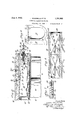
- FIG. 1 is a cross section of an internal combustion engine embodying our invention
- Figure 2 is a fragmentary cross section, similar to Figure 1, taken in the plane of line 22, Figure 3.
- Figure 3 is a top plan view of the engine block with the head removed.
- Figure 4 is an enlarged longitudinal section taken on line 44, Figure 1.
- Figure 5 is an enlarged fragmentary horizontal section taken on line 5-5, Figure 1, the valve being removed from its'chamber to show the lubricating grooves.
- Figure 6 is a fragmentary bottom plan view of the cylinder-head.
- Figure 7 is an enlarged sectional view taken on line 77, Figure 4.
- valve chamber 15 which extends from the 1928. Serial No. 278,270.
- valve-bore is somewhat longer than its plug to compensate for wear of the latter and its front end is closed by a detachable cover plate 18, threaded or otherwise heldin place.
- This valveplug is driven from and synchronized with the crank-shaft of the engine through the medium of any appropriate mechanism and serves to control the admission and expulsion of gases to and from the cylinders.
- a head 19 Extending over the cylinders and valve chamber of the engine-block is a head 19 having passages 20, 21 arranged for communication with the intake and exhaust manifolds (not shown), respectively, the underside of the head having recesses or explosion chambers 22 forming continuatons of said cylinders and extending laterally over the valve chamber.
- the valve chamber 15 In its top wall the valve chamber 15 has a main gas-intake port 23 which is preferably located centrally between the cylinders 11, as shown in Figure 3 and which is in direct communication with the intake passage 20.
- Adjacent its ends the top Wall of the valve chamber has pairs of exhaust ports 25, 26, the port 25 of a pair being in direct communication with the companion exhaust passage 21 and the other port 26 of a pair opening at its upper end into the corresponding chamber 22 of the respective cylinder 11.
- valve-plug 17 which is preferably hollow, is provided in its exterior face or periphery with intake and exhaust recesses or depressions 27, 28, respectively, which are arranged in spiral-like fashion about the valve and are so positioned as to be brought into register with the companion inlet and exhaust ports of the cylinders in accordance with the sion of this 0 the opposing end of the shaft 33 is a cycle of operations of the engine.
- the intake recess 27 of the valve is shown in register with the common intake port 23 and the companion port 24 associated with the right-hand cylinder 11, such recess being of the proper length to bridge said pair of ports, so that the gas upon being admitted to the intake manifold flows through the passage 20 into the port 23, valve-recess 27, port 24 and thence into the explosion chamber 22 of the correspondin cylinder 11.
- the corresponding exhaust recess 28 of the valve is so synchronized that it registers with the exhaust ports 25, 26, allowing the products of combustion to flow from the cylinder through the port 26, valve-recess 28, exhaust port-25 and thence through the passage 21 to the exhaust manifold.
- a tubular driving shaft 30 to the outer end of which is fixed a sprocket wheel 31 adapted for connection to the crank shaft 14 for rotating the valve 17.
- the inner end of this shaft has a square portion 32 for telescopically receiving one end of a universally-jointed driven shaft 33 which is pinned or otherwise connected at its other end to an internal collar 34 of the valve, as seen in Figure 4.
- the front end of the shaftbore isthreaded to receive an adjusting element or bolt 35 and interposed between it and spring 36 which'constantly tends to urge the latter and its valve toward the tapering end'of the valve-chamber 15.
- a slidalble gage or tell-tale rod 38 Extending lengthwise through an opening in the bolt and fixed to a disk 37 interposed between the inner end of the spring 36 and the shaft 33 is a slidalble gage or tell-tale rod 38 whose outer end projects a suitable distance forwardly of the bolt.
- the tell-tale rod may have a gage mark thereon whereby its position relative to erative position.
- the bottom and adjoining sides of its chamber 15 are provided with longitudinal oil-conducting grooves 40 and similar intersecting transverse and diagonal, grooves 41 and42, respectively. Oil is conducted to these several grooves through an inlet conduit 43 connected to one of the diametricallydisposed upper longitudinal grooves 40, the oil thence finding its way to the remaining grooves to thoroughly lubricate the valve.
- an inlet conduit 43 connected to one of the diametricallydisposed upper longitudinal grooves 40, the oil thence finding its way to the remaining grooves to thoroughly lubricate the valve.
- the upper edge 44 of the longitudinal groove 40 directly opposite the companion groove in tersecting grooves 41. 42 and thence through outlets 45 and a conduit 46 to the crank case of the engine.
- outlets 45 may discharge into a com- 1 mon longitudinal passage 47 formed in the engine-block, said outlets being located at one side of the axis of the valve-chamber so that a constant level of oil is always maintained in the bottom of such chamber.
- An internal combustion engine comprising a tapering valve chamber, a correspondingly-shaped rotary valve arranged therein,
- a driving element operatively connected to the valve, means applied to said driving element for constantly urgin the valve toward the tapered end of its chain er, and a gage for indicating the relative position of the valve in said chamber.
- An internal combustion engine comprising a tapering valve chamber, a correspondingly-shaped rotary valve arranged therein, said chamber being longer than said valve, a driving element operatively connected to the valve, means for yieldingly urging the valve toward; the tapered end of its chamber, and a gage controlled by said yieldable means for indicating the relative position of the valve in said chamber.
- An internal combustion engine comprising a tapering valve chamber, a correspondingly-shaped rotary valve therein, said chamber being longer than said valve, a driving shaft for the valve including slidably connected sections capable of relative axial movement, and a spring interposed between said shaft-sections for constantly urging the valve toward the tapered end of its chamber.
- An internal combustion engine com prising a tapering valve chamber, a correlot .
- a driving shaft for the valve including slidably connected sections capable of relative axial movement, a spring interposed between said shaft-sections for constantly urging the valve toward the tapered end of its chamber, and a valve-position indicating member extending lengthwise through one of the shaft-sections and having its inner end disposed beadjoining end of said spring.
- An internal combustion engine comprlsing a tapering valve chamber open at its larger end, a correspondingly-shaped rota-ry valve therein, said chamber being longer than said valve, a cover plate applied to the open end of said chamber, a tubular driving shaft journaled in the cover plate, a driven shaft fixed to said valve and slidably jointed to the driving shaft for permitting axial movement of the valve in its chamber, and a spring applied to the driving shaft for urgmg the driven shaft and the valve connected therewith toward the tapered end of the valve chamber.
- An internal combustion engine comprising a tapering valve chamber open at its larger end, a correspondingly-shaped rotary valve therein, said chamber being longer than said valve, a' cover plate appliedto the open end of said chamber, a tubular driving shaft journaled'in the cover plate, a driven shaft fixed to said valve and slidably jointed to the driving shaft for permitting axial movement of the valve in its chamber and adjusting screw fitted in the outer end of said driving shaft, a spring interposed between the screw and the opposing end of said driven shaft, and a slidable tell-talc rod extending axially through the screw and having a head at its inner end interposed between said spring and said driven shaftythe outer end of the tell-tale rod projecting beyond the corresponding end of the screw.
Landscapes
- Engineering & Computer Science (AREA)
- Mechanical Engineering (AREA)
- General Engineering & Computer Science (AREA)
- Lubrication Of Internal Combustion Engines (AREA)
Description
June 3, 1930. PONTRELLQ ET AL INTERNAL COMBUSTION ENGINE Filed May 16, 1928 2 Sheets-Sheet l JZhuerziara W, M 7% I June 3, 1930. J PONTRELLO ET AL INTERNAL COMBUSTION ENGINE Filed May 16, 1928 2 Sheets-Sheet 2 .1 n venfons 9%,
Patented June 3,1930
PATENT OFFICE JOHN PONTRELLO AND PASQUALE PONTBELLO, OF BUFFALO, NEW YORK INTERNAL-COMBUSTION ENGINE Application filed May 16,
This invention relates generally to improvements in internal combustion engines but more particularly .to a unitary valve structure therefor.
One of its objects is the provision of a unitary valve structure which is common to all the cylinders and whose ports are spirally disposed to effect the admission of fuel to and the exhaust of the products of combustion from the cylinders in accordance with their cycle of operation.
A further object of the-invention is to provide simple and reliable means for taking up the wear of the valve in its cylinder, said means being readily accessible and capable of effecting the adjustment of the valve in a minimum period of time.
' A still further object is the provision of means for effecting the thorough lubrication of the valve.
In the accompanying drawings Figure 1 is a cross section of an internal combustion engine embodying our invention,
' taken in the plane .of line 1-1, Figure 3. Figure 2 is a fragmentary cross section, similar to Figure 1, taken in the plane of line 22, Figure 3. Figure 3 is a top plan view of the engine block with the head removed. Figure 4 is an enlarged longitudinal section taken on line 44, Figure 1. Figure 5 is an enlarged fragmentary horizontal section taken on line 5-5, Figure 1, the valve being removed from its'chamber to show the lubricating grooves. Figure 6 is a fragmentary bottom plan view of the cylinder-head. Figure 7 is an enlarged sectional view taken on line 77, Figure 4.
Similar characters of reference indicate valve chamber 15 which extends from the 1928. Serial No. 278,270.
front to the rear end of said block and contains a rearwardly-tapering bore 16 for receiving a correspondingly tapered revolvable valve-plug 17, the top wall of said chamber being substantially in horizontal alinement with the upper ends of the cylinders. As shown in Figures 4 and 5, the valve-bore is somewhat longer than its plug to compensate for wear of the latter and its front end is closed by a detachable cover plate 18, threaded or otherwise heldin place. This valveplug is driven from and synchronized with the crank-shaft of the engine through the medium of any appropriate mechanism and serves to control the admission and expulsion of gases to and from the cylinders.
Extending over the cylinders and valve chamber of the engine-block is a head 19 having passages 20, 21 arranged for communication with the intake and exhaust manifolds (not shown), respectively, the underside of the head having recesses or explosion chambers 22 forming continuatons of said cylinders and extending laterally over the valve chamber. In its top wall the valve chamber 15 has a main gas-intake port 23 which is preferably located centrally between the cylinders 11, as shown in Figure 3 and which is in direct communication with the intake passage 20. On either side of this intake port, which is a common intake for both cylinders in this particular instance, are supplementary intake ports 24, 24 opening at their upper ends into the lateral portions of the explosion chambers 22 of the head 19. Adjacent its ends the top Wall of the valve chamber has pairs of exhaust ports 25, 26, the port 25 of a pair being in direct communication with the companion exhaust passage 21 and the other port 26 of a pair opening at its upper end into the corresponding chamber 22 of the respective cylinder 11.
The valve-plug 17 which is preferably hollow, is provided in its exterior face or periphery with intake and exhaust recesses or depressions 27, 28, respectively, which are arranged in spiral-like fashion about the valve and are so positioned as to be brought into register with the companion inlet and exhaust ports of the cylinders in accordance with the sion of this 0 the opposing end of the shaft 33 is a cycle of operations of the engine. In Figure 4, the intake recess 27 of the valve is shown in register with the common intake port 23 and the companion port 24 associated with the right-hand cylinder 11, such recess being of the proper length to bridge said pair of ports, so that the gas upon being admitted to the intake manifold flows through the passage 20 into the port 23, valve-recess 27, port 24 and thence into the explosion chamber 22 of the correspondin cylinder 11. After the exploharge take place and the piston is moved upward in its cylinder, the corresponding exhaust recess 28 of the valve is so synchronized that it registers with the exhaust ports 25, 26, allowing the products of combustion to flow from the cylinder through the port 26, valve-recess 28, exhaust port-25 and thence through the passage 21 to the exhaust manifold.
In the initial fitting of the conical valve 17 in its chamber 15, its intake and exhaust ports 27, 28 are so'arranged as to bring their front and rear edges slightly forward of the adjacent edges of the companion ports 23., 2,4 and 25, 26, respectively, as shown in Figure 4, so that when the valve is advanced rearwardly in itschamber to take up wear the several ports will still be insured proper registration to effect the eflicient functioning of the engine.
Journaled in bearings 29 applied to the cover plate 18 is a tubular driving shaft 30 to the outer end of which is fixed a sprocket wheel 31 adapted for connection to the crank shaft 14 for rotating the valve 17. The inner end of this shaft has a square portion 32 for telescopically receiving one end of a universally-jointed driven shaft 33 which is pinned or otherwise connected at its other end to an internal collar 34 of the valve, as seen in Figure 4. The front end of the shaftbore isthreaded to receive an adjusting element or bolt 35 and interposed between it and spring 36 which'constantly tends to urge the latter and its valve toward the tapering end'of the valve-chamber 15. Extending lengthwise through an opening in the bolt and fixed to a disk 37 interposed between the inner end of the spring 36 and the shaft 33 is a slidalble gage or tell-tale rod 38 whose outer end projects a suitable distance forwardly of the bolt. When the valve begins to wear and it is urged rearwardly in its chamber by the spring 36, the tell-tale rod is accordingly moved in the same direction and the exposed end of said rod is shortened more or'less, indicating to the mechanic or operator that there is play of the valve in its chamber and that the bolt 35 should be tightened up to reset the valve until the predetermined exposure of the tell-tale rod is reached. "When this is done, the valve is in its properly set position and reliably held against axial displacement.
If desired, the tell-tale rod may have a gage mark thereon whereby its position relative to erative position. I
For the purpose of effectively lubricating the valve 17, the bottom and adjoining sides of its chamber 15 are provided with longitudinal oil-conducting grooves 40 and similar intersecting transverse and diagonal, grooves 41 and42, respectively. Oil is conducted to these several grooves through an inlet conduit 43 connected to one of the diametricallydisposed upper longitudinal grooves 40, the oil thence finding its way to the remaining grooves to thoroughly lubricate the valve. To prevent an surplus oil finding its way to the upper s1de of the valve chamber and into the inlet and exhaust ports of the motor, the upper edge 44 of the longitudinal groove 40, directly opposite the companion groove in tersecting grooves 41. 42 and thence through outlets 45 and a conduit 46 to the crank case of the engine. As shown in Figures 1, 2 and communication with the inlet conduit, is undercut and acts as a wiper to deflect the surplus oil downwardly through the several 1n- 5, the outlets 45 may discharge into a com- 1 mon longitudinal passage 47 formed in the engine-block, said outlets being located at one side of the axis of the valve-chamber so that a constant level of oil is always maintained in the bottom of such chamber.
We claim as our invention 1. An internal combustion engine, comprising a tapering valve chamber, a correspondingly-shaped rotary valve arranged therein,
said chamber being longer than said valve,
a driving element operatively connected to the valve, means applied to said driving element for constantly urgin the valve toward the tapered end of its chain er, and a gage for indicating the relative position of the valve in said chamber.
2. An internal combustion engine, comprisinga tapering valve chamber, a correspondingly-shaped rotary valve arranged therein, said chamber being longer than said valve, a driving element operatively connected to the valve, means for yieldingly urging the valve toward; the tapered end of its chamber, and a gage controlled by said yieldable means for indicating the relative position of the valve in said chamber.
3. An internal combustion engine, comprising a tapering valve chamber, a correspondingly-shaped rotary valve therein, said chamber being longer than said valve, a driving shaft for the valve including slidably connected sections capable of relative axial movement, and a spring interposed between said shaft-sections for constantly urging the valve toward the tapered end of its chamber. 4. An internal combustion engine, com prising a tapering valve chamber, a correlot . tween the companion shaft-section and the I spondingly-shaped rotary valve therein, said chamber being longer than'said'valve, a driving shaft for the valve including slidably connected sections capable of relative axial movement, a spring interposed between said shaft-sections for constantly urging the valve toward the tapered end of its chamber, and a valve-position indicating member extending lengthwise through one of the shaft-sections and having its inner end disposed beadjoining end of said spring.
5. An internal combustion engine, comprlsing a tapering valve chamber open at its larger end, a correspondingly-shaped rota-ry valve therein, said chamber being longer than said valve, a cover plate applied to the open end of said chamber, a tubular driving shaft journaled in the cover plate, a driven shaft fixed to said valve and slidably jointed to the driving shaft for permitting axial movement of the valve in its chamber, and a spring applied to the driving shaft for urgmg the driven shaft and the valve connected therewith toward the tapered end of the valve chamber.
6. An internal combustion engine, comprising a tapering valve chamber open at its larger end, a correspondingly-shaped rotary valve therein, said chamber being longer than said valve, a' cover plate appliedto the open end of said chamber, a tubular driving shaft journaled'in the cover plate, a driven shaft fixed to said valve and slidably jointed to the driving shaft for permitting axial movement of the valve in its chamber and adjusting screw fitted in the outer end of said driving shaft, a spring interposed between the screw and the opposing end of said driven shaft, and a slidable tell-talc rod extending axially through the screw and having a head at its inner end interposed between said spring and said driven shaftythe outer end of the tell-tale rod projecting beyond the corresponding end of the screw. I
' y JOHN PONTRELLO.
PA'SQUALE PONTRELLO.
Priority Applications (1)
| Application Number | Priority Date | Filing Date | Title |
|---|---|---|---|
| US278270A US1761843A (en) | 1928-05-16 | 1928-05-16 | Internal-combustion engine |
Applications Claiming Priority (1)
| Application Number | Priority Date | Filing Date | Title |
|---|---|---|---|
| US278270A US1761843A (en) | 1928-05-16 | 1928-05-16 | Internal-combustion engine |
Publications (1)
| Publication Number | Publication Date |
|---|---|
| US1761843A true US1761843A (en) | 1930-06-03 |
Family
ID=23064352
Family Applications (1)
| Application Number | Title | Priority Date | Filing Date |
|---|---|---|---|
| US278270A Expired - Lifetime US1761843A (en) | 1928-05-16 | 1928-05-16 | Internal-combustion engine |
Country Status (1)
| Country | Link |
|---|---|
| US (1) | US1761843A (en) |
-
1928
- 1928-05-16 US US278270A patent/US1761843A/en not_active Expired - Lifetime
Similar Documents
| Publication | Publication Date | Title |
|---|---|---|
| US1692845A (en) | Internal-combustion engine | |
| US2111828A (en) | Compression-ignition internal combustion engine | |
| US1761843A (en) | Internal-combustion engine | |
| US1883980A (en) | Fuel pump | |
| US2037051A (en) | Valve timing compensator for internal combustion engines | |
| US1444857A (en) | of detroit | |
| US1398354A (en) | wright | |
| US1515052A (en) | Rotary valve mechanism for engines | |
| US1476359A (en) | Slide-valve internal-combustion engine | |
| US1760853A (en) | Engine-valve-operating means | |
| US1623416A (en) | Double-acting internal-combustion engine | |
| US2110828A (en) | Compression-ignition internal combustion engine | |
| US1298429A (en) | Engine. | |
| US1315788A (en) | murray | |
| US1885911A (en) | Sleeve-valve engine | |
| US1514280A (en) | Internal-combustion engine | |
| US1891321A (en) | Internal combustion engine | |
| US1689689A (en) | Internal-combustion engine | |
| US1652380A (en) | Engine valve | |
| US1594654A (en) | Internal-combustion engine | |
| US1673734A (en) | Valve mechanism for explosive engines | |
| US3011591A (en) | Engine lubricating system | |
| US1410315A (en) | Rotary valve for internal-combustion motors | |
| US1290413A (en) | Explosive-engine. | |
| US1068724A (en) | Explosive-engine. |