US1761830A - Hair clamp - Google Patents
Hair clamp Download PDFInfo
- Publication number
- US1761830A US1761830A US232067A US23206727A US1761830A US 1761830 A US1761830 A US 1761830A US 232067 A US232067 A US 232067A US 23206727 A US23206727 A US 23206727A US 1761830 A US1761830 A US 1761830A
- Authority
- US
- United States
- Prior art keywords
- hair
- clamp
- rod
- strip
- engaging
- Prior art date
- Legal status (The legal status is an assumption and is not a legal conclusion. Google has not performed a legal analysis and makes no representation as to the accuracy of the status listed.)
- Expired - Lifetime
Links
- 238000009499 grossing Methods 0.000 description 5
- 239000012858 resilient material Substances 0.000 description 5
- 239000000463 material Substances 0.000 description 3
- 238000004804 winding Methods 0.000 description 2
- AGJBKFAPBKOEGA-UHFFFAOYSA-M 2-methoxyethylmercury(1+);acetate Chemical compound COCC[Hg]OC(C)=O AGJBKFAPBKOEGA-UHFFFAOYSA-M 0.000 description 1
- 230000000994 depressogenic effect Effects 0.000 description 1
- 238000010438 heat treatment Methods 0.000 description 1
- 238000010025 steaming Methods 0.000 description 1
Images
Classifications
-
- A—HUMAN NECESSITIES
- A45—HAND OR TRAVELLING ARTICLES
- A45D—HAIRDRESSING OR SHAVING EQUIPMENT; EQUIPMENT FOR COSMETICS OR COSMETIC TREATMENTS, e.g. FOR MANICURING OR PEDICURING
- A45D2/00—Hair-curling or hair-waving appliances ; Appliances for hair dressing treatment not otherwise provided for
- A45D2/02—Hair winders or hair curlers for use substantially perpendicular to the scalp, i.e. steep-curlers
- A45D2/04—Hair winders or hair curlers for use substantially perpendicular to the scalp, i.e. steep-curlers in the form of rods with jaw devices
Definitions
- This invention relates to a hair clamp, and particularly to a. hair clamp for use in conjunction with a curling rod in preparing human hair to receive a permanent wave l ndenv the practice commonly pursued.
- One object of the invention is to provide a hair clamp which will yieldingly engage a curling rod .and the hair thereon to avoid the necessity of tying thehair to the rod.
- Another object of-the invention is to provide a hair clamp of this nature which will smooth outrand engage the loose endsof a lock ortress after it has been wound on the curling rod, and as the clamp is applied thereto.
- 3 w l g 7 Another object, of the invention is toprovide a hair clamp ofthis nature which is held in position by its own resiliency, and which may be readily disenga ed from the curling rod to whichit is app ied.
- Figure 1 is a'. plan view of the hair clamp;
- Figure 2 is aside elevation thereof;
- Figure 3 is an end view of the hair clamp;
- Figure 4 is a plan view of a hair curler and clamp, showing a lock or'tress of'hair wound on the curler prior to its smoothing out and engagement by the clamp;
- Figure 5 is a side elevation illustrating the operation of smoothing out the free end of the lock or tress ofhair;
- Figure 6 is a plan view of the curler and clamp showing the clamp in its finalengaging position, -with the hair smoothed out and clamped thereby;
- Figure 7 is a plan view of a modified form of clamp;
- Figure 8 is a side elevation thereof;
- the tress 1 In preparing alock or tress of hair in the operation of permanent waving the tress 1" is tied at a point 2 adjacent the head of the person. This tress 1 is then wound smoothly on a curler3, which is' desirably a curler such as is shown and described in my prior Patent N 0. 1,199,550, dated September 26, 1926. This winding is performed either by hand, or by some suitable winding means, such as that shown and described in my copendingapplication Serial No. 316,304 filed October 31, 1928, as a continuation of application Serial No. 253,023, filed February 9, 1928. 1
- the clamp itself as shown in Figures 1 to 6 inclusive, comprises a relatively flat forward portion 4 from which extend curved gripping members 5 for engaging the curler.
- the connecting member 6 consists in a strip of resilient material, which extends upwardly and rearwardly from the forward portion 4: and then downwardly and rearwardly therefrom. This portion or member 6 carries curved rod engaging menibers or portions 7.
- the clamp is slipped over the end of the curler 3which is removed from the point 2 at which the hair is tied.
- EX- tending forwardly from the flat portion 4: of the clamp is an extension or teat 8, hav ing a smoothly curved edge 9.
- the clamp as a Whole is moved further along the curling rod to firmly clamp the tress thereto, as shown particularly in Figure 6 of the drawings.
- the resilient connecting member 6 is released, and the curling rod 18 engaged bythespace within the gripping members as 1 to insure a firm engagement with the curling rod.
- the clamp remains in position during the operation of heating or steaming the hair to form the permanent wave. a When the hair is to be removed from the curling rod at the completion of the operatiomthe resilient. connecting member 6 is again I depressed to raise the forward portion 4 and teat 8 of the clamp, sothat the clamp as a whole may be withdrawn rearwardly from thecurling rod. 5 I N
- a simplified form of the clamp is shown in Figures 7 to 9 inclusiveof the drawings. This simplifiedfor'm comprises merely a flat upper portion 12, curved gripping members 13 extending therefrom, and a forwardly.
- the collecting edge'1-5' of the teat' 14 serves to smooth out members 13 have their ends 17 separated a outturned to permit ofaready engagement relatively great distance, and these ends.
- the clamp of the present'inventionfpr'ovl des a simple and HIQ'XPGHSIVGHIGHLHS for engaging a tress-of hair to a "curlingrod' It also serves to without tying it thereto. I smooth out and engage loose ends'of hair,
- the c'lamp may be made of resilientmetal, or o'fan'y other suitable resilient material. As shown, it'is' an integral structure formed from a con-1' said strip.
- a hair' clamp comprising ayielding j yielding'hair engaglng pertiony a nd a hair. 7 e
- her having acurvedha r collect ngedge her having acurvedha r collect ngedge.
- a hair-clamp comprising alstrip of re silie nt material; a resilient member comprising curved embracing legsintegral with said strip for engaging a circular body; and
- a hair clamp comprising spaced mem bers for engaging acir'cular bodygastrip of V i Q g' a p pri ng" paced mema y resilientmaterialoffset partway of itslength I connecting said members and hair engaging means extending from said strip.
- a hair clamp comprisinga pertionarranged to engage a curl-ing jrodfa yielding hair engaging, portion, and a hair smooth- In witness WllQIQOf fI hereunto set myP-f L U-LE.;HE R
Landscapes
- Hair Curling (AREA)
Description
June 3, 1930. P. E. HERRMANN 1,761,830
HAIR CLAMP Filed Nov. 9, 1927 7 i w I 6 FIB. 2 5
FIG. I
INVENTOR PCLU HeTrman-n his aflor ne Patented June 3, 1930 UNITED. STATES PATENT OFFICE.
renn n. HERRMANN, or NEW YORK, n. Y., ASSIGNOR r0 HERRMANN SUPPLY 00M- IANY ING, OF NEW YORK, N. Y.,
A. CORPORATION OF NEW YORK HAIR CLAMP l Application filed November 9, 1927. Serial No. 232,067.
This invention relates to a hair clamp, and particularly to a. hair clamp for use in conjunction with a curling rod in preparing human hair to receive a permanent wave l ndenv the practice commonly pursued.
One object of the invention is to provide a hair clamp which will yieldingly engage a curling rod .and the hair thereon to avoid the necessity of tying thehair to the rod.
Another object of-the invention is to provide a hair clamp of this nature which will smooth outrand engage the loose endsof a lock ortress after it has been wound on the curling rod, and as the clamp is applied thereto. 3 w l g 7 Another object, of the invention is toprovide a hair clamp ofthis nature which is held in position by its own resiliency, and which may be readily disenga ed from the curling rod to whichit is app ied.
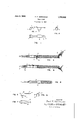
Inthe accompanying drawings Figure 1 is a'. plan view of the hair clamp; Figure 2 is aside elevation thereof; Figure 3 is an end view of the hair clamp; Figure 4 is a plan view of a hair curler and clamp, showing a lock or'tress of'hair wound on the curler prior to its smoothing out and engagement by the clamp; Figure 5 is a side elevation illustrating the operation of smoothing out the free end of the lock or tress ofhair; Figure 6 is a plan view of the curler and clamp showing the clamp in its finalengaging position, -with the hair smoothed out and clamped thereby; Figure 7 is a plan view of a modified form of clamp; Figure 8 is a side elevation thereof;
and Figure 9 is an end view of thismodified.
clamp.
In preparing alock or tress of hair in the operation of permanent waving the tress 1" is tied at a point 2 adjacent the head of the person. This tress 1 is then wound smoothly on a curler3, which is' desirably a curler such as is shown and described in my prior Patent N 0. 1,199,550, dated September 26, 1926. This winding is performed either by hand, or by some suitable winding means, such as that shown and described in my copendingapplication Serial No. 316,304 filed October 31, 1928, as a continuation of application Serial No. 253,023, filed February 9, 1928. 1
The clamp itself, as shown in Figures 1 to 6 inclusive, comprises a relatively flat forward portion 4 from which extend curved gripping members 5 for engaging the curler. The connecting member 6 consists in a strip of resilient material, which extends upwardly and rearwardly from the forward portion 4: and then downwardly and rearwardly therefrom. This portion or member 6 carries curved rod engaging menibers or portions 7.
vVith particular reference to Figure e of the drawings, the clamp is slipped over the end of the curler 3which is removed from the point 2 at which the hair is tied. EX- tending forwardly from the flat portion 4: of the clamp is an extension or teat 8, hav ing a smoothly curved edge 9. With the clamp in the position shown in Figure 4,
pressure is exertedon the upper face of the portion 6 of the clamp, to maintain the gripping members 5 in disengaged position, and to raise the teat 8. The teat 8 is then moved forwardly over the loose ends 1* of the tress 1, asshownin dotted lines. In this position the clamp as a whole is rotated in the direction in which the hair is wound,
and as a result the loose ends 1 are then gathered into the curved edge 9 of the teat and are smoothed out under it, so that they are wholly engaged between the curling rod 3 and the clamp.
When the loose ends of the hair have been thus smoothed out, the clamp as a Whole is moved further along the curling rod to firmly clamp the tress thereto, as shown particularly in Figure 6 of the drawings. When the clamp is in this position the resilient connecting member 6 is released, and the curling rod 18 engaged bythespace within the gripping members as 1 to insure a firm engagement with the curling rod. a
The clamp remains in position during the operation of heating or steaming the hair to form the permanent wave. a When the hair is to be removed from the curling rod at the completion of the operatiomthe resilient. connecting member 6 is again I depressed to raise the forward portion 4 and teat 8 of the clamp, sothat the clamp as a whole may be withdrawn rearwardly from thecurling rod. 5 I N A simplified form of the clamp is shown in Figures 7 to 9 inclusiveof the drawings. This simplifiedfor'm comprises merely a flat upper portion 12, curved gripping members 13 extending therefrom, and a forwardly.
projecting'teat 14 having a smoothly "curved hair collecting edge 15. In order that the forwardly projecting teat 14 may pass over the looseends of hair to be smoothedbut and engaged it is provided with an upturned forward edge 16. When the teat '14 is passed over the loose ends of hairin the sa'me'man ner as with the previously described form of clamp, and as shown in Figure 5, the re; siliency 0f the teat 14 permits it to readily ride over these loose ends. W hen the clamp the loose ends in the same manner as with the previously described form of clamp.
With this form the gripping portions or is rotated on the curling rod,*the collecting edge'1-5' of the teat' 14 serves to smooth out members 13 have their ends 17 separated a outturned to permit ofaready engagement relatively great distance, and these ends. are
with the curling rod 8. During the operation of clamping a tress to the curling rod,
the clamp'is brought to ,a position over the red where the loose end of the 'hair'l is located; Then the back-12 is pressed, and
this causes the resilient members 13 to snap over the rod-3, and it remains in place on the rod 3 due to friction between said rod and the members 13'.
I The clamp of the present'inventionfpr'ovldes a simple and HIQ'XPGHSIVGHIGHLHS for engaging a tress-of hair to a "curlingrod' It also serves to without tying it thereto. I smooth out and engage loose ends'of hair,
which cannot be coiled on the rod by means" of mechanical, winder, and which are 'difli cult to smooth-out by hand. 'The c'lamp may be made of resilientmetal, or o'fan'y other suitable resilient material. As shown, it'is' an integral structure formed from a con-1' said strip.
ing member extending from saidhair en} gaging portion,'said hair smoothing member having a curved hair collecting edge.
- 2. A hair' clamp comprising ayielding j yielding'hair engaglng pertiony a nd a hair. 7 e
portion arranged to engage a curling rod, a
smoothing "r'nei'i'nber extending from said hair v engaging portion, said hair smoothing mem.-
her having acurvedha r collect ngedge.
. 8. A hair-clamp comprising alstrip of re silie nt material; a resilient member compris ing curved embracing legsintegral with said strip for engaging a circular body; and
means extendi-ngfrom said: strip to guide flthe hair as'in operation theclampisirotated and to-clampthe hair'o'r'r-ftherod;v
4. A hair clamp 'comprisingfa, strip of 're-.'
silient material 'offsetpartway {of its length, 7 v areslhent member comprising curved emf.
bracin 'le s inte al with s'aidstri forengaging a circular. body, and meansex'tending from said strip to vguide the hair 'as in 'op-I eration the clamp is r the hair onthefrod. v I
5. A hair'clamp 'comprisin'gfa strip ref resilient material offset partway of Tits dtated 11a, to. amp
length, means forengag-ing a circular body a i I connected with said wee ener engaging;
means havmg acurved hair collee'tlnged ge V extending from said strip.-
I 6. A hair clamp comprising spaced mem bers for engaging acir'cular bodygastrip of V i Q g' a p pri ng" paced mema y resilientmaterialoffset partway of itslength I connecting said members and hair engaging means extending from said strip.
" 8. A hair clamp'comprising spaced Inembers for engaging a c1rcula1 l,bod y,a stripof resilient material connecting said mem bers, and a hair engaging member having a curved hair collecting 'edge'extending from said strip. 7
.9. A hairYcl'ainpcomprisingspacedlmem-f bers forengaginga circular body, 'a st'rip of resilientmaterial offset partway o'fits length connecting said members, and "a hair engage ing ememb'er'having a curved hair collecting edge extending from said strip. I
hand.
tinuous piece of sheet of material. It will I be understood however, that the various per tions or members of the clamp may be made separately if so desired, and fastened tov gether by any suitable fastening means. v
"What I claim. is: g 1. A hair clamp "comprisinga pertionarranged to engage a curl-ing jrodfa yielding hair engaging, portion, and a hair smooth- In witness WllQIQOf fI hereunto set myP-f L U-LE.;HE R
Priority Applications (1)
| Application Number | Priority Date | Filing Date | Title |
|---|---|---|---|
| US232067A US1761830A (en) | 1927-11-09 | 1927-11-09 | Hair clamp |
Applications Claiming Priority (1)
| Application Number | Priority Date | Filing Date | Title |
|---|---|---|---|
| US232067A US1761830A (en) | 1927-11-09 | 1927-11-09 | Hair clamp |
Publications (1)
| Publication Number | Publication Date |
|---|---|
| US1761830A true US1761830A (en) | 1930-06-03 |
Family
ID=22871741
Family Applications (1)
| Application Number | Title | Priority Date | Filing Date |
|---|---|---|---|
| US232067A Expired - Lifetime US1761830A (en) | 1927-11-09 | 1927-11-09 | Hair clamp |
Country Status (1)
| Country | Link |
|---|---|
| US (1) | US1761830A (en) |
-
1927
- 1927-11-09 US US232067A patent/US1761830A/en not_active Expired - Lifetime
Similar Documents
| Publication | Publication Date | Title |
|---|---|---|
| US2201719A (en) | Curl clip | |
| US2212212A (en) | Arm support for fishing rods | |
| US1884305A (en) | Hair curling apparatus and method | |
| US1652279A (en) | Hair-waving device | |
| US1761830A (en) | Hair clamp | |
| US2452025A (en) | Brush support | |
| US2215292A (en) | Support for electric sadiron cords | |
| US2422716A (en) | Hair curler | |
| US2242549A (en) | Hair curling device | |
| US2308167A (en) | Hair curler | |
| US2083614A (en) | Anchor for ladies' hats | |
| US1552618A (en) | Hair curler | |
| US1592688A (en) | Hair curler | |
| US1654775A (en) | Hair-retaining means | |
| US2926407A (en) | Incision closing clip | |
| US2808675A (en) | Fishing reel locking device | |
| US2265492A (en) | Hair curler | |
| US1528643A (en) | Hair-curl holder | |
| US2103526A (en) | Hair curler | |
| US2207953A (en) | Dental floss holder | |
| US2631594A (en) | Hair curler | |
| US2013258A (en) | Hair curler | |
| US2034729A (en) | Hair curling apparatus | |
| US2865072A (en) | Bow tie and frame means therefor | |
| US2125421A (en) | Apparatus for waving hair |