US1761822A - Feeding mechanism for nut-cracking machines - Google Patents
Feeding mechanism for nut-cracking machines Download PDFInfo
- Publication number
- US1761822A US1761822A US269174A US26917428A US1761822A US 1761822 A US1761822 A US 1761822A US 269174 A US269174 A US 269174A US 26917428 A US26917428 A US 26917428A US 1761822 A US1761822 A US 1761822A
- Authority
- US
- United States
- Prior art keywords
- nuts
- nut
- drum
- chute
- pockets
- Prior art date
- Legal status (The legal status is an assumption and is not a legal conclusion. Google has not performed a legal analysis and makes no representation as to the accuracy of the status listed.)
- Expired - Lifetime
Links
- 238000005336 cracking Methods 0.000 title description 18
- 235000009025 Carya illinoensis Nutrition 0.000 description 1
- 241001453450 Carya illinoinensis Species 0.000 description 1
- 235000014676 Phragmites communis Nutrition 0.000 description 1
- 230000015572 biosynthetic process Effects 0.000 description 1
- 230000005484 gravity Effects 0.000 description 1
- 230000002093 peripheral effect Effects 0.000 description 1
Images

Classifications
-
- A—HUMAN NECESSITIES
- A23—FOODS OR FOODSTUFFS; TREATMENT THEREOF, NOT COVERED BY OTHER CLASSES
- A23N—MACHINES OR APPARATUS FOR TREATING HARVESTED FRUIT, VEGETABLES OR FLOWER BULBS IN BULK, NOT OTHERWISE PROVIDED FOR; PEELING VEGETABLES OR FRUIT IN BULK; APPARATUS FOR PREPARING ANIMAL FEEDING- STUFFS
- A23N5/00—Machines for hulling, husking or cracking nuts
Definitions
- This invention relates to nut cracking machines and, among other objects, aims to provide improved high speed nutfeeding mechanism adapted to supply a single nut ata f '5 time to a rotating 'drum and' means to insure perfect lay-downs of the nuts in their respective pockets ready kto be gripped properly by the cracking mechanism.
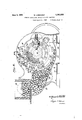
- Fig. l is a side elevation, partly in Section of ⁇ avnut cracking machine'embodying the invention
- Fig. 2 is a sectional view taken on the line 2-2 of Fig. 1, parts being shown in eleva- 1 5 tion;
- Fig. 3 is a top plan View of the nut feeding mechanism shown in Fig. 1.
- V beingA applied to a'machine of the same general type,'as that described in my prior Pat- :ent No. 1,133,121, dated ⁇ March 23, 1915. Thatis to say/,the machine is of thevrotary carrier kor, drum type wherein a plurality of A-plungers operate in nut receiving pockets,
- a base l() havin end plates or supports 11 carrying a fixed 130 yshaft 12 Von which is mounted al rotary carrier or drum 18 (Fig. 1) having the usual ⁇ nut receiving pocket-s 14 in its periphery in which the plungers 15 are adapted to be reciprocated by operating mechanism of ⁇ any
- the drum 13 is shown as having an integral annular flange 18 at Vone end adjacent to the nut pockets and this flange preferably has af peripheral groove 19 V to receive a sectional annular rim or iiange constituting a pick-up wheel 20, each section .A
- the pick-up devices on the rim are shown as comprising crescentshaped spoons 21 secured thereto by means of Screws 22 passing through abutting arcuate ianges 23.
- These pick-up spoons have a highly polished inclined pockety 24: out of which the nuts are adapted to slide without material' frictional resistance and fall on the bridge pieces 16 of the drum at the propertime.
- the idea of detachably securing the spoons to the feedk wheel is to permit spoons of different sizes for different grades or sizes of nuts to be used on the same machine.
- a sec'- tional casing 25 having its parts bolted together about the drum and providing an annular 'space 26 in which the feed wheel rotates.
- the casing n walls are 'shown as being extended to pro- 'vide a nuthopper having an inclined bottom wall 27, (Fig. 2) thearrangement being such as to supply nuts to the pick-up spoons as the feed wheel rotates.
- the nuts may be supplied to and kept at a constant level in the hopper by a screw conveyor 28 and are preferably agitated to prevent the formation of voids by means of a pair of disks 29 arranged on a driven shaft 30 and having knob-like projections to engage the nuts.
- the cas- ⁇ ing 25 is hewn asfhavingintegral iianges 3l and 32 on opposite Sides of the feed wheel adjacent'to the spoons 21 and the Hange. 32
- ,40 sectional casing 2'51 has ,af discharge chute 38 leading to an opening39 the baselOlv .of
- thev arrangement is such asto insure'v that there will be no missers because the spoons are eausedto'pass through a pick-upfzoney in the hopper whereinthe nuts are always free" of large voids.
- nular iiange' member vdetalch'ably yconnected K l' 4 l to the drum", a plurality off pick-up spoons 90 detachably connected to' the flange member adapted topiclr up one nut at a time-to be ydropped c into ⁇ 'said j chute V;'y and agfeed' hopper tosupplyrnutstovsaidifeeder; 3.
- V'ln a nutV crackingy deliver nuts tothe cracking.mechanism;v rotary feeder ⁇ fixed on thefdruin ad] ac'ent to a the chute and ⁇ hagm'g ra Vplurfa'ility offdetachable'fpich-up members secured; theretoyfa5510112yk feed.y hopper kthrough whichflgjthegpickup n, ine'mbers rotate ja'ndHangejmembels ZQLOPrE l' '.posite v sides ofl .the feeder l:over whichI the 'surplus nutsfall back into the' hop-peri;l L
- a feeder comprising an annular rim connected to the drum; and a plurality of pick-,up spoons detachably conandh'aving inclined poladapted to slide.
- a feeder comprising a sectional annular rim removably connected to the drum; and a plurality of pick-up spoons detachably connected to the rim and having inclined polished surfaces over Which Vthe nuts are adapted toslide.
- a feeder compresenting means interlocking With the drum and detachably connected thereto; and a plurality of pick-up spoons .detachably secured to the periphery of said rim.
- a rotary feed Wheel having pick-up, crescent-shaped spoons detachably secured to the periphery Y thereof; and means onv the machine cooperating with the spoons to support the knuts in proper feeding positions and yto prevent doubles7 from being conveyed to the machine in a single spoon.
- a rotary nut feeder a nut hopper through which the feeder rotates; a nut supplying conveyor extending into the hopper and arranged to supply nuts thereto and maintain them at a substantially constant level therein; and
- a chute to deliver nuts' to the drum; feeding means to deliver nuts to the chute; bridges on the -drum between the pockets on Which the nuts are adapted to fall; and means associated with the chute to strikethe nuts and cause them to lie properly in the pockets.
- a chute to deliver nuts to the drum; feeding means to deliver nuts to the chute; bridges on the drum between the pockets on which the nuts are adapted to fall; a pivoted gate on the chute arranged to strike any vnuts standing on their ends and cause them to lie properly in the drum pockets; and a loosely journaled roller adjacent to the pivoted gate arranged to ,press vthe nuts into the bottom ⁇ of the pockets.
- a chute to deliver the nuts to the drum pockets and means associated with one Wall of the chute to engage the nuts carried by the drum and cause them to lie perfectly in the drum pockets whereby they Will be engaged by the nut .cracking mechanism.
Landscapes
- Life Sciences & Earth Sciences (AREA)
- Chemical & Material Sciences (AREA)
- Engineering & Computer Science (AREA)
- Food Science & Technology (AREA)
- Polymers & Plastics (AREA)
- Filling Or Emptying Of Bunkers, Hoppers, And Tanks (AREA)
Description
w. GEBHARDT 1,761,822
FEEDING MECHANISM FOR NUT CRACKING MACHINES Filed April l1., 1928 2 Sheets-Sheet 1 @Qld/ful,
ATTORNEYS June 3, 1930.
June 3, 1930. w. cal-:BHARDT A 1,761,822
FEEDING MECHANISM FOR NUT CRACKING MACHINES l 1 Filed April 11, 19428 2 Sheets-Sheet 2 e VENT WW y M j' gT-ORNE'YS 35 approved design.
f lamented June 3, 1930 l UNITED STATES @PATENT oFFIcE -wrLLrAM GEBHARDT,CF SAN ANTONIO, TEXAS, ASsIGNoR To er. A. DUERLER MANU# y FACTURING COMPANY, or SANANTONIO, TEXAS, A kooiaroiuicrrorar or` TEXAS rEED'rNG MECHANISM FOR NUT-GRACKING MACHINES l Application filed April 11, 1928. Serial No. 269,174.
- This invention relates to nut cracking machines and, among other objects, aims to provide improved high speed nutfeeding mechanism adapted to supply a single nut ata f '5 time to a rotating 'drum and' means to insure perfect lay-downs of the nuts in their respective pockets ready kto be gripped properly by the cracking mechanism. p
In the accompanying drawings,
Fig. l is a side elevation, partly in Section of `avnut cracking machine'embodying the invention;
' Fig. 2 is a sectional view taken on the line 2-2 of Fig. 1, parts being shown in eleva- 1 5 tion; and
' 1 Fig. 3 is a top plan View of the nut feeding mechanism shown in Fig. 1.
Referring particularly to the drawings the n improved feeding mechanism is shownv as V beingA applied to a'machine of the same general type,'as that described in my prior Pat- :ent No. 1,133,121, dated` March 23, 1915. Thatis to say/,the machine is of thevrotary carrier kor, drum type wherein a plurality of A-plungers operate in nut receiving pockets,
firstto gripthe nuts and then, to crack them by the usual cam roperating means. v Herein, there is shown a base l() havin end plates or supports 11 carrying a fixed 130 yshaft 12 Von which is mounted al rotary carrier or drum 18 (Fig. 1) having the usual `nut receiving pocket-s 14 in its periphery in which the plungers 15 are adapted to be reciprocated by operating mechanism of `any These features may be similar to those shown in my-pror patent and, hence, require no further description. 'Howeveig the spaces between the pockets in the drum, here Shown, are preferably bridged by linverted Vsubstantially -U-shaped bridge members 16 secured to the drum and having their opposite edges clamped against the edges of the pocket bushings 17, these bridges being so arranged that nutsl fall on them before they enter their respective pockets.
.Referring to Fig. 1 the drum 13 is shown as having an integral annular flange 18 at Vone end adjacent to the nut pockets and this flange preferably has af peripheral groove 19 V to receive a sectional annular rim or iiange constituting a pick-up wheel 20, each section .A
'having a tongue fitting-inthe groove, the
arrangement being such that this sectional rim may be advanced or retarded in order that the nuts may fall on the bridges at the proper time to insure that they will dropin the receiving pockets. The pick-up devices on the rim are shown as comprising crescentshaped spoons 21 secured thereto by means of Screws 22 passing through abutting arcuate ianges 23. `These pick-up spoons have a highly polished inclined pockety 24: out of which the nuts are adapted to slide without material' frictional resistance and fall on the bridge pieces 16 of the drum at the propertime. The idea of detachably securing the spoons to the feedk wheel is to permit spoons of different sizes for different grades or sizes of nuts to be used on the same machine.
Moreover, the Spoons are often damagedsov that'they do not function properly and this arrangement permits them to be replaced.
Referring to Fig. l, there is Shown a sec'- tional casing 25 having its parts bolted together about the drum and providing an annular 'space 26 in which the feed wheel rotates. On one side of the drum, the casing n walls are 'shown as being extended to pro- 'vide a nuthopper having an inclined bottom wall 27, (Fig. 2) thearrangement being such as to supply nuts to the pick-up spoons as the feed wheel rotates. The nuts may be supplied to and kept at a constant level in the hopper by a screw conveyor 28 and are preferably agitated to prevent the formation of voids by means of a pair of disks 29 arranged on a driven shaft 30 and having knob-like projections to engage the nuts.
Referrin' now to Figs. l and 3,'the cas-` ing 25 is hewn asfhavingintegral iianges 3l and 32 on opposite Sides of the feed wheel adjacent'to the spoons 21 and the Hange. 32
1s provided with an opening in which a nut 'feed chute 33 is detachably secured. -The inner edgeof this flange is beveled at 34 between the bottom of the hopper and the vmouth of the chute to provide'a fixed supporting abutment for the ends of the nuts carried in the pick-up spoons. The arrangement is such that all surplus nuts forced by Vthe spoons above the nut level in the hopper' will fall back onl either side of the feed wheel and roll down the outsideof the two flanges 31 and 32 (Fig. 3).` This is veryAimpor-tant because it is essential to avoid feeding doubles7 to the drum pockets. singles carried to the mouth of the chute 33 will always fall end-wise into `it,y im1nef diately'after the lower open ends of the chute is shown, as having; apivotedand weighted trapk gate orflapv 35y so larranged that any nuts whichmay be, standing on end *in their pockets will strike its :lower edge when they pass underit and `will be-pushed downy so that they vWilllie properlycinthe pockets.- Theflap` or gate willswing by gravity to thel position- 'shown in Figg after 'thev nuts strike it.,- Also, in!V Figui?,
` there isshownaa'rloosely'journaledy roller 36" l,mounted betweeen y arms 37 projecting rearwardly'from the rear vwall ofthe chute and being so ar'rangedfthat'the nuts inthe pock- I jetsf'will roll under itand bepressedagainst 1 their seats justVbefore-they, are grippedgby the plungers. The rolleris free to rollover 3o the vbridge pieces and I fall onthe nuts lbe-l low `themiin the pockets. rllhe nuts roll yundertit and are pressed; against their seats, thus stopping any jrockingmotion Vwhich oval .shaped pecans are likely toYhave-before 35 they/are gripped between the jaws. .It `will Y be understood that the nuts ywillfbe[cracked v by theplungers yduring,the'krotatio'n ,of the machine and will be ejected from their pockets-at some suitable pointy-Herein, the
,40 sectional casing 2'51 has ,af discharge chute 38 leading to an opening39 the baselOlv .of
to crack nutsof a diierentgrade or size ,and f that the spoonsmaybechanged to accom modate nuts of different sizes; Moreover, thev arrangement is such asto insure'v that there will be no missers because the spoons are eausedto'pass through a pick-upfzoney in the hopper whereinthe nuts are always free" of large voids.
,doublesn to the ldrum and thereby avoids Further, it will not feed j producing imperfectly cracked nuts. Also,
the nuts valways fall at the proper time, Y into the feed chute out of thelpolishedl spoon Also, the. l'
i 'speen-s pass the inner edge ofthe chute e Toinsure that' thev nuts rwill lie'perfectlyx in the pockets 14E, ready to be gripped .end-ff wise by the plungers, the rear wallV of-"thev 'ng deseripuma willy be Obviously, the-present- 'invention yis not -e restricted to the particular* embodiment `thereoffherein.shown anddescribed.VV l\[ore.k v over, it is not Vvindispensable' that all the` featuresrof the invention Vbe used conjointly,
since theyfmay'` be employedadvantageously in vvvarious combinati-'ons `and sub-combinations, i, y if ,Y -V f4 Nhatlis'claimed is: l A' 1 ,v ln combination'fwit v u lmachine of the *rotary "dru1nf type," achute to deliver nuts vgtothe, drum; .a rotatable Ynut feeder adjustablyvsecuredto said drum and havinga plurality' ofH detachable pickup devices each adapted :to deliveronenut go `atta time tofsaid chute in proper timed relation fte fall into aY socket in ,the 'i drum ;A and -a hopper havingagitating means tosup'ply f nuts tosaidfeeder. f'
In combinationwithga nut cracking ina-85 n e Y -f nuts utothe drum,akg'rotatablelfnut feeder as-V i sociatedA withl saidi drum: including an an.- y
nular iiange'; member vdetalch'ably yconnected K l' 4 l to the drum", a plurality off pick-up spoons 90 detachably connected to' the flange member adapted topiclr up one nut at a time-to be ydropped c into` 'said j chute V;'y and agfeed' hopper tosupplyrnutstovsaidifeeder; 3. V'ln a nutV crackingy deliver nuts tothe cracking.mechanism;v rotary feeder `fixed on thefdruin ad] ac'ent to a the chute and `hagm'g ra Vplurfa'ility offdetachable'fpich-up members secured; theretoyfa5510112yk feed.y hopper kthrough whichflgjthegpickup n, ine'mbers rotate ja'ndHangejmembels ZQLOPrE l' '.posite v sides ofl .the feeder l:over whichI the 'surplus nutsfall back into the' hop-peri;l L
acter described, nut 'delivering chute y-to f `which the pickfup members? rotate; and` an arcuate yiangemeinber adjacenfff tothe 'feed- 'i "er between i the chute and the hopper I larranged tosuPPOrt yone'fend4 of.jeachii-iuty in fthe pick-up members and presentingfa surf 2115" face` over which surplus nuts fall baclinto Y the hopper( 1 r l 1 M 5. ln .a nut 'cracking-machine ofthe ro'- taryl drum type, av nutv deliveringfchuteto -V deliver nutsV `to the .cracl'r-ingl mechanism; a i120 A 1 rotary Y' feedenon thesdrum'adjacent tothe e fchuter-and-,having-La pluralityof detachable,
pick-up members securedftheretogga feed vvhope-per through whichA the pick-up members rotate; and azcasing abeut said feeder hav'lz Y fi ling annular. flange niemb'e'rsl onjop'posite K sides of-theffeeder, one-'o fsaid flanges on that `side adj acent 'tof the .chute jp-resenting sa' bevellefdgedge against rwhich the ends of `v Y thegnutsfare supportedfin thegpiekfu'p inem-V m30 n Y n p l vmachine ofthe char-f95;'V 'y'. acterdescribed, `a1-nut delivering chute to e e .In afnut'v cracking machine` of theehar-,zem f deliver nuts to: the,cracking;mechanismg a rotary feederadjacentto 'they chutefandl-iavf l ing aplurality of detachablepick-up mem,-
e lbers secured thereto; afeed'rhopperlthrough110i knected to therim ished surfaces. over Which the nuts are vprising a sectional annular rim bers and both of the flanges providing outer surfaces over which surplus nuts fall back into the hopper.
6. In combination With a rotary drum nut cracking machine, a feeder comprising an annular rim connected to the drum; and a plurality of pick-,up spoons detachably conandh'aving inclined poladapted to slide.
7. In combination With a rotary drum nut cracking machine, a feeder comprising a sectional annular rim removably connected to the drum; and a plurality of pick-up spoons detachably connected to the rim and having inclined polished surfaces over Which Vthe nuts are adapted toslide.
` 8. In combination with a nut cracking machine of the rotary'drum type, a feeder compresenting means interlocking With the drum and detachably connected thereto; and a plurality of pick-up spoons .detachably secured to the periphery of said rim.
In combination with a nut cracking machine of the character described, a rotary feed Wheel having pick-up, crescent-shaped spoons detachably secured to the periphery Y thereof; and means onv the machine cooperating with the spoons to support the knuts in proper feeding positions and yto prevent doubles7 from being conveyed to the machine in a single spoon.
10. In Vvcombination'vvith a rotary nut feeder, a nut hopper through which the feeder rotates; a nut supplying conveyor extending into the hopper and arranged to supply nuts thereto and maintain them at a substantially constant level therein; and
an agitator within the hopper adjacent Vto the feeder `to eliminate voids Within this mass of nuts. t
ll. In combination With a nut cracking machine havinga rotary drum and nut receiving pockets therein, a chute to deliver nuts' to the drum; feeding means to deliver nuts to the chute; bridges on the -drum between the pockets on Which the nuts are adapted to fall; and means associated with the chute to strikethe nuts and cause them to lie properly in the pockets.
, 12,'Inv combination With a nut cracking machine having a rotary drum and nut receiving pockets therein,"a chute to deliver nuts to the drum; feeding means to deliver nuts to the chute; bridges on the drum between the pockets on which the nuts are adapted to fall; a pivoted gate on the chute arranged to strike any vnuts standing on their ends and cause them to lie properly in the drum pockets; and a loosely journaled roller adjacent to the pivoted gate arranged to ,press vthe nuts into the bottom `of the pockets. n I
,13. In combination `With a 'rotary' drum nut cracking machine, a chute to deliver the nuts to the drum pockets and means associated with one Wall of the chute to engage the nuts carried by the drum and cause them to lie perfectly in the drum pockets whereby they Will be engaged by the nut .cracking mechanism.
nature.
n WILLIAM GEBHARD'I.
a i rotary nut
Priority Applications (1)
| Application Number | Priority Date | Filing Date | Title |
|---|---|---|---|
| US269174A US1761822A (en) | 1928-04-11 | 1928-04-11 | Feeding mechanism for nut-cracking machines |
Applications Claiming Priority (1)
| Application Number | Priority Date | Filing Date | Title |
|---|---|---|---|
| US269174A US1761822A (en) | 1928-04-11 | 1928-04-11 | Feeding mechanism for nut-cracking machines |
Publications (1)
| Publication Number | Publication Date |
|---|---|
| US1761822A true US1761822A (en) | 1930-06-03 |
Family
ID=23026114
Family Applications (1)
| Application Number | Title | Priority Date | Filing Date |
|---|---|---|---|
| US269174A Expired - Lifetime US1761822A (en) | 1928-04-11 | 1928-04-11 | Feeding mechanism for nut-cracking machines |
Country Status (1)
| Country | Link |
|---|---|
| US (1) | US1761822A (en) |
-
1928
- 1928-04-11 US US269174A patent/US1761822A/en not_active Expired - Lifetime
Similar Documents
| Publication | Publication Date | Title |
|---|---|---|
| US2065319A (en) | Hopper feed | |
| US1711464A (en) | Grinding machine | |
| US3581949A (en) | Controlled volumetric feeding apparatus | |
| US1761822A (en) | Feeding mechanism for nut-cracking machines | |
| GB1179683A (en) | Improvements relating to apparatus for Feeding Rod-like Articles | |
| CN206285980U (en) | A kind of wood chip pulverizer | |
| US2362517A (en) | Cartridge orientor | |
| US2273783A (en) | Washer feeding device | |
| US2321795A (en) | Nut cracking machine | |
| US1541163A (en) | Centrifugal drier | |
| US1879897A (en) | Grinding and mixing apparatus | |
| CN211090558U (en) | Pomegranate seed and pulp separator | |
| US2230790A (en) | Nut cracking machine | |
| US2689667A (en) | Machine for orienting and dispensing stamped metal lock nut blanks | |
| US3690068A (en) | Continuous treating apparatus | |
| CN104146048A (en) | Snail meat and shell separator | |
| US3583547A (en) | Machine for feeding and orienting workpieces | |
| CN108741122B (en) | Peanut shelling device | |
| US2204039A (en) | Treatment of grain, especially wheat | |
| CN202823464U (en) | Propelling device of corn degerminator | |
| US997592A (en) | Grinding-mill. | |
| US1920946A (en) | Rotary material reducing machine | |
| US420427A (en) | Sugar-cane-slicing machine | |
| US1307692A (en) | Date-shkedder | |
| CN215625468U (en) | Peach slice finishing machine |