US1753698A - Instrument for drafting irregular curves - Google Patents
Instrument for drafting irregular curves Download PDFInfo
- Publication number
- US1753698A US1753698A US232677A US23267727A US1753698A US 1753698 A US1753698 A US 1753698A US 232677 A US232677 A US 232677A US 23267727 A US23267727 A US 23267727A US 1753698 A US1753698 A US 1753698A
- Authority
- US
- United States
- Prior art keywords
- rods
- instrument
- bars
- blocks
- drafting
- Prior art date
- Legal status (The legal status is an assumption and is not a legal conclusion. Google has not performed a legal analysis and makes no representation as to the accuracy of the status listed.)
- Expired - Lifetime
Links
- 230000001788 irregular Effects 0.000 title description 4
- 239000000969 carrier Substances 0.000 description 8
- 238000010276 construction Methods 0.000 description 4
- 230000015572 biosynthetic process Effects 0.000 description 1
- 230000003247 decreasing effect Effects 0.000 description 1
- 239000000463 material Substances 0.000 description 1
Images

Classifications
-
- B—PERFORMING OPERATIONS; TRANSPORTING
- B43—WRITING OR DRAWING IMPLEMENTS; BUREAU ACCESSORIES
- B43L—ARTICLES FOR WRITING OR DRAWING UPON; WRITING OR DRAWING AIDS; ACCESSORIES FOR WRITING OR DRAWING
- B43L13/00—Drawing instruments, or writing or drawing appliances or accessories not otherwise provided for
- B43L13/20—Curve rulers or templets
- B43L13/22—Adjustable curve rulers
Definitions
- the present invention is directed to improvements in instruments for drafting irregular curves, and has for its object to generally improve and simplify the constructions disclosed in my prior Patents, Nos. 962,896 and 1,054,109 issued June 28, 1910 and February 25, 1913, respectively.
- Another object of the invention is to provide an instrument of this character including a plurality of carriers to which the rule carrying rods can be easily and quickly at tached and held in adjusted positions in an extremely simple manner, and further to pro vide a novel form of connection between the rule carrying rods and rod carriers to enable the rule to lie flat upon the paper.
- Figure 1 is a top plan view of the implement.
- Figure 2 is an end view thereof.
- Figure 3 is a transverse sectional view through one of the carriers.
- Figure 5 is a detail perspective View of the rule supporting block.
- Figure 6 is a detail sectional view through the same.
- Figure 7 is a detail sectional view through the rule supporting head.
- Figure 8 is a similar view showing another use of the head.
- Figure 9 is a similar view showing a rule in the head.
- Figure 10 is a similar view showing another form of rule.
- the implement comprises a frame 1 which includes a pair of end blocks 2 which have A fixed in their corners the ends of the guide rods 3 formed from suitable gage'stock.
- Slidable upon the frame 1 is a plurality of rod carriers 1, six of which are shown, but it will be of course understood that the number may be decreased or increased, as desired.
- These carriers include blocks 5 having bores Gin which are mounted circularrod. supporting heads 7 said heads being pivotally mounted in the bores by screws 8 whichgare threaded in the blocks from diametrically opposite points, as clearly shown in Figure a of the drawings, and will obviously permit the heads to swing. 7
- the lowermost bolts 8 merely serve as pivotal connections, whereas the-upper bolts may be manipulatedthrough the medium of the knobs 10 to clamp the blocks 5 to the adjacent bars, thus holding said blocks against pivotal movement and permitting thesame to be rocked for adjustment'and clamped in a selected adjusted position.
- the bars 9 are provi led at one of their ends with set screws 12 for engaging the associated rods 3 to clamp the bars and thus the carrier in selected position upon the rod 3.
- the rod supporting heads 7 are; formed with openings 13 in which are fixed the inner ends of the tubes M, the outer ends thereof being slit, as at 15, to provide gripping jaws 16 controlled by the chuck collars 17 threaded on said tubes.
- the adjusting rods 18 are capable of. having their inner ends engaged in the jaws 16 and are held in. adjusted positions upon operating the chuck collars 17. Owing to the presence of the tubes 14: rods may be extended thereinto during adjustment.
- the rods 18 vary in length in order that they may be used in making lines of various curvatures.
- An instrument of the class described comprising a plurality of parallel guide rods, bars adjustable on the rods, blocks rotatably connected with the bars, and'having bores therein, heads pivotally mounted in the bores I and having tubes fitted therein, a flexible rule, rods for supporting the rule, and means for adj ustably connecting the supporting rods in the tubes.
- An instrument of the class described comprising a plurality of parallel guide rods, bars slidably engaging the guide rods, blocks mounted between the bars and rotatably engaged therewith, said blocks having bores therein, heads pivotally mounted in the bores, ruler supporting rods, and means for adjustably and detachably connecting the said rods with the heads.
- An instrument of the class described comprising a plurality ofparallel guide rods, bars having their ends slidably engaged with the rods, means for holding the bars in fixed,
- carriers including blocks, said blocks being mounted between the bars and pivotally connected thereto, means for. holding the blocks clamped with the bars to prevent accidental rotation thereof, said blocks having bores therein, heads pivotally mounted in the bores and having their pivotal axes disposed at right angles with respect to the pivotal axes between the bars and blocks, a flexible ruler or straight edge, rods for engagement with the ruler. or straight edge, and means for detachably connecting the lastnamed rods with the heads.
Landscapes
- Treatment Of Fiber Materials (AREA)
Description
April 8, 1930. A. GASPARICH msmumau'r FOR Dan-TING IRREGULAR CURVES Filed Nov. 11. 1927 2 sheets-sheet 1 v Jnucufoz v/Qni'orrembelfla April 1930- A. GASPARICH 1,753,698
INSTRUMENT FOR DRAFTIVNG IRREGULAR cuRvfis Filed Nov. 11, 1927 2 Sheets-Sheet 2 Patented Apr. 8, 1930 UNITED sra'rss i ANTON GASPARICI-I, or OAKLAND, CALIFORNIA INSTRUMENT FOR DRAFTING IRJREGJJILIAIBJCURVES" Application filed November 11, 1927. Serial No. 2323677.
The present invention is directed to improvements in instruments for drafting irregular curves, and has for its object to generally improve and simplify the constructions disclosed in my prior Patents, Nos. 962,896 and 1,054,109 issued June 28, 1910 and February 25, 1913, respectively.
Another object of the invention is to provide an instrument of this character including a plurality of carriers to which the rule carrying rods can be easily and quickly at tached and held in adjusted positions in an extremely simple manner, and further to pro vide a novel form of connection between the rule carrying rods and rod carriers to enable the rule to lie flat upon the paper.
With these and other objects in view, this invention resides in the novel features of construction, formation, combination and ar- 29 rangement of parts to be hereinafter more fully described, claimed and illustrated in the accompanying drawings, in which,-
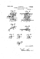
Figure 1 is a top plan view of the implement.
Figure 2 is an end view thereof. Figure 3 is a transverse sectional view through one of the carriers.
Figure 4; is a sectional view on line 4.4= of Figure 3. V
Figure 5 is a detail perspective View of the rule supporting block.
Figure 6 is a detail sectional view through the same.
Figure 7 is a detail sectional view through the rule supporting head.
Figure 8 is a similar view showing another use of the head.
Figure 9 is a similar view showing a rule in the head. 1 Figure 10 is a similar view showing another form of rule.
The implement comprises a frame 1 which includes a pair of end blocks 2 which have A fixed in their corners the ends of the guide rods 3 formed from suitable gage'stock.
Slidable upon the frame 1 is a plurality of rod carriers 1, six of which are shown, but it will be of course understood that the number may be decreased or increased, as desired.
These carriers include blocks 5 having bores Gin which are mounted circularrod. supporting heads 7 said heads being pivotally mounted in the bores by screws 8 whichgare threaded in the blocks from diametrically opposite points, as clearly shown in Figure a of the drawings, and will obviously permit the heads to swing. 7
In order to maintain the carriers upon the, rods 3 the upper and lower sidesthereof have secured thereto by boltsS cross bars 9, the bolts carried by the top bars having knobs 10- thereon. The ends of the bars are provided with transverse openings 11 for slidably receiving the rods 3. Owing, to the. presence of the bolts 8 the members 4 may be swung when: desired, the pivotal axis thereof being disposed at right angles to the pivotal axis o-fthe' heads 7 in order that the carriers may have a universal movement.
The lowermost bolts 8 merely serve as pivotal connections, whereas the-upper bolts may be manipulatedthrough the medium of the knobs 10 to clamp the blocks 5 to the adjacent bars, thus holding said blocks against pivotal movement and permitting thesame to be rocked for adjustment'and clamped in a selected adjusted position. I
The bars 9 are provi led at one of their ends with set screws 12 for engaging the associated rods 3 to clamp the bars and thus the carrier in selected position upon the rod 3.
The rod supporting heads 7 are; formed with openings 13 in which are fixed the inner ends of the tubes M, the outer ends thereof being slit, as at 15, to provide gripping jaws 16 controlled by the chuck collars 17 threaded on said tubes.
The adjusting rods 18 are capable of. having their inner ends engaged in the jaws 16 and are held in. adjusted positions upon operating the chuck collars 17. Owing to the presence of the tubes 14: rods may be extended thereinto during adjustment. The rods 18 vary in length in order that they may be used in making lines of various curvatures.
The outer ends of the rods 18 have carried thereby heads 19 carrying the pivotally connected blocks 20 in which are formed clovetailedf grooves 21and sockets 22, and since this construction is similarto that disclosed,
in my Patent No. 1,054,109, a more detailed description is not thought necessary. As in my former patent flexible rules or straight edges 23 may be connected in the grooves 21 and in Figure 9 I have illustrated pins 23 carried by the straight edge secured in sockets 22. In Figure 8 I have illustrated a flexible strip 24 which is adapted to fit in the grooves 21 and serves as a guide in order that the rods 18 may be set and upon removal of the strip a selected straightedge or ruler substituted therefor for actual use. 7
Since the ruler or straight edge is formed from flexible material it will be obvious that 1 J simple in construction, efficient in operation,
durable, but can bemanufactured at a very small cost.
As shown in Figure 1 the rods are disposed in parallel relation and extend from one side Having thus described the invention, I
claim:
1. An instrument of the class described, comprising a plurality of parallel guide rods, bars adjustable on the rods, blocks rotatably connected with the bars, and'having bores therein, heads pivotally mounted in the bores I and having tubes fitted therein, a flexible rule, rods for supporting the rule, and means for adj ustably connecting the supporting rods in the tubes.
2. An instrument of the class described comprising a plurality of parallel guide rods, bars slidably engaging the guide rods, blocks mounted between the bars and rotatably engaged therewith, said blocks having bores therein, heads pivotally mounted in the bores, ruler supporting rods, and means for adjustably and detachably connecting the said rods with the heads.
3. An instrument of the class described comprising a plurality ofparallel guide rods, bars having their ends slidably engaged with the rods, means for holding the bars in fixed,
adjusted position upon therods, carriers including blocks, said blocks being mounted between the bars and pivotally connected thereto, means for. holding the blocks clamped with the bars to prevent accidental rotation thereof, said blocks having bores therein, heads pivotally mounted in the bores and having their pivotal axes disposed at right angles with respect to the pivotal axes between the bars and blocks, a flexible ruler or straight edge, rods for engagement with the ruler. or straight edge, and means for detachably connecting the lastnamed rods with the heads.
In testimony whereof I alfix my signature.
ANTON GASPARIOI-l. [1,. s.] g
Priority Applications (1)
| Application Number | Priority Date | Filing Date | Title |
|---|---|---|---|
| US232677A US1753698A (en) | 1927-11-11 | 1927-11-11 | Instrument for drafting irregular curves |
Applications Claiming Priority (1)
| Application Number | Priority Date | Filing Date | Title |
|---|---|---|---|
| US232677A US1753698A (en) | 1927-11-11 | 1927-11-11 | Instrument for drafting irregular curves |
Publications (1)
| Publication Number | Publication Date |
|---|---|
| US1753698A true US1753698A (en) | 1930-04-08 |
Family
ID=22874093
Family Applications (1)
| Application Number | Title | Priority Date | Filing Date |
|---|---|---|---|
| US232677A Expired - Lifetime US1753698A (en) | 1927-11-11 | 1927-11-11 | Instrument for drafting irregular curves |
Country Status (1)
| Country | Link |
|---|---|
| US (1) | US1753698A (en) |
Cited By (1)
| Publication number | Priority date | Publication date | Assignee | Title |
|---|---|---|---|---|
| US2883756A (en) * | 1957-02-25 | 1959-04-28 | Greist Mfg Co | Trimming guides |
-
1927
- 1927-11-11 US US232677A patent/US1753698A/en not_active Expired - Lifetime
Cited By (1)
| Publication number | Priority date | Publication date | Assignee | Title |
|---|---|---|---|---|
| US2883756A (en) * | 1957-02-25 | 1959-04-28 | Greist Mfg Co | Trimming guides |
Similar Documents
| Publication | Publication Date | Title |
|---|---|---|
| US1750218A (en) | Key-cutting machine | |
| US1753698A (en) | Instrument for drafting irregular curves | |
| GB321835A (en) | Improvements in or relating to woodworking machines | |
| US543492A (en) | laughlin | |
| US2312154A (en) | Drafting apparatus | |
| US1771903A (en) | Proportioning drafting instrument | |
| US2243778A (en) | Glass cutter | |
| US2091262A (en) | Pattern grading | |
| US1452828A (en) | Adjustable spacing tool | |
| US785756A (en) | Adjustable measuring and ruling device. | |
| US3029004A (en) | Device for making returns, pleats, and spaces in draperies | |
| US973047A (en) | Ellipsograph. | |
| US802028A (en) | Apparatus for scribing curved figures. | |
| US1539704A (en) | Squaring device for cuts and films | |
| US2887775A (en) | Multiple degree gage | |
| US2152904A (en) | Lettering guide or the like | |
| US696046A (en) | Ellipsograph. | |
| US3367029A (en) | Grading tool devices, especially adaptable for use in the garment industry | |
| US2375447A (en) | Scarfing device | |
| US1920839A (en) | Pointing device for stone carvers | |
| US1007910A (en) | Ellipsograph-machine. | |
| US2074922A (en) | Rule cutting machine | |
| US1441939A (en) | Drawing apparatus | |
| US2298635A (en) | Letter form and guide for the same | |
| US1464945A (en) | Ruling-machine guide |