US1753673A - Door for radiant gas heaters - Google Patents
Door for radiant gas heaters Download PDFInfo
- Publication number
- US1753673A US1753673A US375412A US37541229A US1753673A US 1753673 A US1753673 A US 1753673A US 375412 A US375412 A US 375412A US 37541229 A US37541229 A US 37541229A US 1753673 A US1753673 A US 1753673A
- Authority
- US
- United States
- Prior art keywords
- door
- cabinet
- flange
- radiant gas
- gas heaters
- Prior art date
- Legal status (The legal status is an assumption and is not a legal conclusion. Google has not performed a legal analysis and makes no representation as to the accuracy of the status listed.)
- Expired - Lifetime
Links
- XEEYBQQBJWHFJM-UHFFFAOYSA-N Iron Chemical compound [Fe] XEEYBQQBJWHFJM-UHFFFAOYSA-N 0.000 description 2
- 229910052742 iron Inorganic materials 0.000 description 1
- 239000002184 metal Substances 0.000 description 1
- 229910052751 metal Inorganic materials 0.000 description 1
- 230000000284 resting effect Effects 0.000 description 1
Images
Classifications
-
- F—MECHANICAL ENGINEERING; LIGHTING; HEATING; WEAPONS; BLASTING
- F24—HEATING; RANGES; VENTILATING
- F24C—DOMESTIC STOVES OR RANGES ; DETAILS OF DOMESTIC STOVES OR RANGES, OF GENERAL APPLICATION
- F24C15/00—Details
- F24C15/02—Doors specially adapted for stoves or ranges
Definitions
- This invention relates to that type of radiant gas-heater in which the burners and radiants are mounted within a cabinet of the console type, such, for instance, as shown in my copending application Serial N 0. 279,288, filed May 21, 1928, the present application being a division of that application.
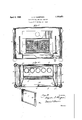
- Fig. l is a vertical sectional view of the cabinet
- Fig. 2 is a horizontal sectional view there- 0 r Fig. 3 is a detail perspective view of one of the doors.
- 5 designates the radiants mounted within the cabinet 6 just back of a rectangular opening in the front-wall of the cabinet.
- This opening in the front-wall isadapted to be closed by a pair of doors 7, one of which islocated at each end of the cabinet.
- Each of these doors is adapted to run straight back into the cabinet, the lower edge of the door resting and being guided in a channelidly supported within the cabinet.
- ach door consists of a single plate of sheet metal flanged at its edges to give it stiffness. Extending across each'door, near its rear end, between the top and bottom flanges, is a stop-flange 10 and .at the front end of each door each of the flanges is provided with an extension-flange'll which is turned inwardly. When the door is pulled straight forwardly, in its channel 8, the vertical flange 10 strikes against a laterally-extending flange 12 and the door is arrested in its outward movement thereby.
- the door may be swung around, with the flange 12 acting as a sort of hinge, to its closed position, where it is substantially flush with the front face of the cabinet, the door being arrested in this position by a stop 13 located at the bottom and centrally of the door-opening.
- the outer flange of the channel 8 isbent laterally toward the adjacent end of the cabinet, as at 14, to widen the channel at this point. W'henthe door is thus swung around to closed position,
Landscapes
- Engineering & Computer Science (AREA)
- Chemical & Material Sciences (AREA)
- Combustion & Propulsion (AREA)
- Mechanical Engineering (AREA)
- General Engineering & Computer Science (AREA)
- Wing Frames And Configurations (AREA)
Description
April 8, 1930. A. F. THOMPSON DOOR FOR RADIANT GAS HEATERS Original Filed May 21, 1928 n n I n I i 5 iron 8 mounted upon a horizontal Patented Apr. 8, 1930 UNITED STATES AUGUSTUS F. THOMPSON, or HUNTINGTON, wnsrvmerma DOOR FOR RADIANT GAS HEATERS Original application filed May 21, 1928, Serial No. 279,288. Divided and this application file'd ma z 1929. Serial No. 375,412. r r
This invention relates to that type of radiant gas-heater in which the burners and radiants are mounted within a cabinet of the console type, such, for instance, as shown in my copending application Serial N 0. 279,288, filed May 21, 1928, the present application being a division of that application.
In the drawing annexed Fig. l is a vertical sectional view of the cabinet; V
Fig. 2 is a horizontal sectional view there- 0 r Fig. 3 is a detail perspective view of one of the doors.
Referring to the drawing annexed by reference-numerals, 5 designates the radiants mounted within the cabinet 6 just back of a rectangular opening in the front-wall of the cabinet. This opening in the front-wall isadapted to be closed by a pair of doors 7, one of which islocated at each end of the cabinet. Each of these doors is adapted to run straight back into the cabinet, the lower edge of the door resting and being guided in a channelidly supported within the cabinet.
ach door consists of a single plate of sheet metal flanged at its edges to give it stiffness. Extending across each'door, near its rear end, between the top and bottom flanges, is a stop-flange 10 and .at the front end of each door each of the flanges is provided with an extension-flange'll which is turned inwardly. When the door is pulled straight forwardly, in its channel 8, the vertical flange 10 strikes against a laterally-extending flange 12 and the door is arrested in its outward movement thereby. From this position, the door may be swung around, with the flange 12 acting as a sort of hinge, to its closed position, where it is substantially flush with the front face of the cabinet, the door being arrested in this position by a stop 13 located at the bottom and centrally of the door-opening. To permit the door to thus swing around to closed position, the outer flange of the channel 8 isbent laterally toward the adjacent end of the cabinet, as at 14, to widen the channel at this point. W'henthe door is thus swung around to closed position,
plate 9 rig 1ts rear or inner-end its rear end engages the laterally-bent flange 14 of the channel to thus guide the end of the door to a position against the adjacent part of the front wall of the cabinet. When both doors are thus closed, they meet at the center and thereby close the front opening in the cabinet. It will be observed that the stopflange 12 is secured to a vertical post supported within the cabinet and that this stop-flange 12 lies a short distance back of the front face of the cabinet, so thatthe door when closed is sufliciently inset to come substantially flush with the front face of the cabinet. It will be observed also that, when the door is closed,
its inturned flange 11 strikes against the outer face of a vertical flange 12 and arrests the door with its outer end practically flush with the face of the cabinet, so that, whether the doors be open or closed,'they will not project outwardly beyond flange carried by the cabinet and setback within the door-opening, whereby when the doors are drawn outwardly tothe fullest extent and swung inwardly toward each other. they will lie substantially flush with the front wall of the cabinet.
2. In combination with a cabinet having a door-opening in its front wall, a door-guiding-and-su porting channel at each side of opening extending rearwardly into the cabinet, a door having its bottom edge throughout its length slidably mounted in each of these channels and equal to half the area of the door-opening, each door being provided with a stop-flange at a distance from the face of the cabinet. front-wall, thereby reducing to a minimum the liability of the doors being bent or broken.
adapted to strike against and hinge upon an adjacent Vertical flange carried by the cabinet and set back within the door-opening, whereby when the doors are drawn outwardly to the fullest extent and swung inwardly toward'each other they will lie substantially flush with the front-wall oi the cabinet, the outer flange of each one of said channel-irons being bent laterally to permit the rear end of the door to contact with the inner face of the fi'ont wall of net when the door is closed. V
In testimony whereof I hefeunto afiix my signature. AUGUSTUS F. THOMPSON.
the Gabi-
Priority Applications (1)
| Application Number | Priority Date | Filing Date | Title |
|---|---|---|---|
| US375412A US1753673A (en) | 1928-05-21 | 1929-07-02 | Door for radiant gas heaters |
Applications Claiming Priority (2)
| Application Number | Priority Date | Filing Date | Title |
|---|---|---|---|
| US279288A US1738335A (en) | 1928-05-21 | 1928-05-21 | Radiant gas heater |
| US375412A US1753673A (en) | 1928-05-21 | 1929-07-02 | Door for radiant gas heaters |
Publications (1)
| Publication Number | Publication Date |
|---|---|
| US1753673A true US1753673A (en) | 1930-04-08 |
Family
ID=26959567
Family Applications (1)
| Application Number | Title | Priority Date | Filing Date |
|---|---|---|---|
| US375412A Expired - Lifetime US1753673A (en) | 1928-05-21 | 1929-07-02 | Door for radiant gas heaters |
Country Status (1)
| Country | Link |
|---|---|
| US (1) | US1753673A (en) |
Cited By (1)
| Publication number | Priority date | Publication date | Assignee | Title |
|---|---|---|---|---|
| US4219006A (en) * | 1978-02-24 | 1980-08-26 | Arnfinn Nesje | Stove-hearth combinations |
-
1929
- 1929-07-02 US US375412A patent/US1753673A/en not_active Expired - Lifetime
Cited By (1)
| Publication number | Priority date | Publication date | Assignee | Title |
|---|---|---|---|---|
| US4219006A (en) * | 1978-02-24 | 1980-08-26 | Arnfinn Nesje | Stove-hearth combinations |
Similar Documents
| Publication | Publication Date | Title |
|---|---|---|
| US2439664A (en) | Glass-lined metal shelf wall closet | |
| US2296950A (en) | Oven cabinet, shelf, and door | |
| US2773728A (en) | Medicine cabinets | |
| US2166534A (en) | Right and left opening door and hanger structure | |
| US1753673A (en) | Door for radiant gas heaters | |
| US2302217A (en) | Door for broiler drawers | |
| US3046974A (en) | Door stop mechanism | |
| US3304932A (en) | Removable oven door | |
| US2063376A (en) | Stove construction | |
| US1885404A (en) | Oven rack operating mechanism | |
| US1665028A (en) | Support for flexible doors of kitchen cabinets | |
| US2230475A (en) | Wardrobe or locker | |
| US2683446A (en) | Oven door stop mechanism | |
| US2705947A (en) | Frameless range construction | |
| US2492084A (en) | Counterbalance means for oven doors | |
| US1632733A (en) | Metal receptacle | |
| US2018876A (en) | Doorcheck | |
| US2086472A (en) | Filing appliance | |
| US2207046A (en) | Hinge | |
| US2110176A (en) | Stove door | |
| US2720000A (en) | Drawer stop | |
| US1530007A (en) | Stove-door construction | |
| US2598419A (en) | Door or closure | |
| US1865331A (en) | Catch for oven doors | |
| US1428579A (en) | Stove door |