US1745515A - Permanent mold for making castings - Google Patents
Permanent mold for making castings Download PDFInfo
- Publication number
- US1745515A US1745515A US100821A US10082126A US1745515A US 1745515 A US1745515 A US 1745515A US 100821 A US100821 A US 100821A US 10082126 A US10082126 A US 10082126A US 1745515 A US1745515 A US 1745515A
- Authority
- US
- United States
- Prior art keywords
- drag
- cope
- liner
- mold
- shell
- Prior art date
- Legal status (The legal status is an assumption and is not a legal conclusion. Google has not performed a legal analysis and makes no representation as to the accuracy of the status listed.)
- Expired - Lifetime
Links
- 238000005266 casting Methods 0.000 title description 42
- 239000011797 cavity material Substances 0.000 description 54
- 239000002184 metal Substances 0.000 description 5
- 239000011435 rock Substances 0.000 description 5
- 241000357293 Leptobrama muelleri Species 0.000 description 3
- 241000607686 Salmonella enterica subsp. enterica serovar Thompson Species 0.000 description 3
- 238000010276 construction Methods 0.000 description 3
- 229910000831 Steel Inorganic materials 0.000 description 1
- 230000000295 complement effect Effects 0.000 description 1
- 208000002925 dental caries Diseases 0.000 description 1
- 238000006073 displacement reaction Methods 0.000 description 1
- 210000005069 ears Anatomy 0.000 description 1
- 239000007789 gas Substances 0.000 description 1
- 239000010959 steel Substances 0.000 description 1
Images


Classifications
-
- B—PERFORMING OPERATIONS; TRANSPORTING
- B22—CASTING; POWDER METALLURGY
- B22C—FOUNDRY MOULDING
- B22C9/00—Moulds or cores; Moulding processes
- B22C9/06—Permanent moulds for shaped castings
Definitions
- the invention has for its objectsto lighten, the weight and to dispose 3 and halancethe parts. of'the mold whereby toreduc'e the'laborand .promote the coni .5 venienceofoperating themold; to provide.
- Fig. 6 is a detail perspective View of the I 0 which is supported inthe mold cavity ing-a selected embodiment of the inventionfor embedment in the casting of a brake shoe. 7
- i Fig. 7 is a front elevation of the mold.
- Fig. 8 is a transverse sectional view on the line 88 ofFig. 5.
- Fig.9 is a side elevation similar to Fig. 1, showing the mold in open position and a completed brake shoeas made in the mold.
- the mold comprises a drag 10 and a cope 11 having a mold cavity 12 therein adapted for casting a brake shoe.
- the drag isv in skeleton form and comprises a'shell 13 which is arranged in inclined position and is mounted upon supporting rails 14, which constitute the base for the mold.
- a drag liner 15 is removably mounted on the shell13 of the drag and it is provided with centering pins 16 adapted to enter openings 17 in the shell for positioning the drag lineron the shell.
- Two pairs of bolts 18 provided with nuts 19 and lock nuts 20 are arranged onthe shell to form supports for the drag liner. These bolts can be adjusted as required to properly position the drag liner with relation to the cope andalso to accommodate difi'erent'drag liners.
- the rear end 21 of thecope forms one end of the mold cavity and it extends down to a position behind the drag liner where it is pivoted at 22 to the forwardly projecting arms 23 of the'bell crank yoke 24, which is pivoted at: 25 to the upstanding lugs 26 on the shell 18 of the drag.
- Parallel links 27 are pivoted at 28 at theirrear ends to the bell: crank yoke 2ft and'at 29 at their front ends to the upper ends of the bell crank levers 30 which are pivoted at 31 on the sides of the cope at the front thereof.
- the rear- Wardly projecting arms of the bell crank levers 30 have rounded bearing surfaces 32 arranged to engage complementary bearings 33 on the.
- bearing plates 34 which are fastened on the sides of the drag, being here shown conveniently bolted to the drag liner 15.
- Pins 35 are fixed in the copeabove the bearing arms of the bell crank levers 30, and these pins project only a short distancefrom thesides of the cope so that they Will be engaged by said arms, but "Will be cleared by the links 27 Fig.
- the cope can con veniently be made in skeleton form comprising a shell 36 having two sides 36 and an arched front 36", and it is adapted to receive a removable cope liner 37.
- the cope in arecess 41 in the cope liner.
- Thecope liner 87 and the drag liner 15 have the mold cavity 12 formed in their opposing faces with the parting line of the mold cavity disposed to permit the cope to be freely removed from the drag afterv the casting has beenmade.
- I provide tapered lugs 42 on the cope shell to engage beveled edges 43 on the drag liner, so that when the cope is lowered into position upon the drag liner the lugs on the cope shell engaging the beveled edges on'the drag liner will register the cope in proper position on the drag liner.
- the pouring gate 44 is pivoted at 45 upon the forked upper end 46 of a lever 47 which is pivoted at 48 upon lugs 49 on the drag shell 10.
- the lower end of this pouring gate lever is pivoted at 50 to links 51, which are also pivoted at 52 g to the lever arm 53 rigidly mounted upon the rock shaft 54'supported in ears 55 on the drag shell.
- a counterbalanced lever 56 is rigidly mounted on one end of the'rock shaft for operating the lever 47 'to move the pouring gate into or out of operative position relative to the drag and the cope.
- the rear end of the mold cavity is closed by the end 21 of the cope; the front end of the mold cavity is open to permit the molten metal to flow into the cavity'therethrough; and this open front end of.
- the mold cavity is covered by the pouring gate which is constructed to fitsnugly against the front ends of the drag-liner and the cope liner.
- the pouring cavity. 57 in the pouring gate extends downward insubstantial size and its bottom 58 is inclined when the pouring gate .is in closed position to correspond approxisand-core 59 is arranged in the cavity pouring mately with the inclination of the mold so that the molten metal will flow easily through the pouring gate into the mold cavity.
- This sand core projects over a part of the end of the mold cavity and reduces the size ofthe neck which connects the sprue with the casting so that the sprue can. be easily knocked off of the casting by a comparatively light blow.
- This 'c'ore also protects the cope liner against the cutting action of the molten metal in pouring. I f
- A'tensioning device is arranged to engage the legs of the loop and it comprises a lever 69 pivoted at 70 on the cross-bar 67 and, having an operating handle 71 (Fig. 4).
- a detent 7 2 of any suitable construction is arranged to engage a toothed segment 73 mounted on the cope shell.
- the legs of the wire loop arelocatedon opposite sides of the support66 and the'crossbar 67.
- the lever 69 In initial position the lever 69 is arranged angularly to the support 66 and the cross-bar 67 and between the openings 63 so 1 that when the wire loop 62 is arranged in place the lever 69 will-project through the loop, as shown in Fig. 3.
- the tensioning lever 69 is shifted from initial position (Fig. to tensloning position (Fig. 4). The tension lever thus-produces a partial twist of the looped wire, as clearly indicated in Fig.4,
- the cope liner is provided with a recess 74 to accommodate the lug 61 and also the core 75 which is inserted g in the lug to form the key opening in the attaching lug of the shoe.
- a handle lever 76 is secured by the pivot bolt 22 to the bell crank yoke 24 and is fulcrumed by the pivot bolt 25 on the drag shell.
- This lever is operated to swing the cope between closed position (Fig. 1) and open posi-' tion (Fig. 9.), the opening movement being limited by a stop 77 upon which the cope rests.
- Fig. 9 I have shown the brake shoe 7 8 as it appears whenit is lifted from ice the drag after themold is opened atthe con-.
- My invention provides a permanent mold of simple construction and adapted to be.
- the mold is tilted atan angle to facilitate the pouringoperation and also to posi tion' the parts most advantageously for opening the mold and for securing the insert in the cope.
- the pivoted pouring gate provides ing gate can be swung to closed position by poourin ate to closed osition.
- the pouring gate is not only pivoted to swingin an arc to and from the mold, but itis pivoted on its supporting lever so that itwill automatically adjust itself to proper position against the mold. counterbalanced .to facilitate its operation and to insure that the pouring gate will remain in snug contact with the drag and the cope liners during the casting operation.
- the cope is ITIOVB'Cl initially away fromthe drag ina right line to clear the drag and the casting, and then it is swung in an arc to open position, as shown in Fig. 9.
- the operating handle .76 is conveniently located for swinging the cope between open and closedpositions andthe inclined position of the .mold facilitates this operation.
- the insert When the cope is in open position the insert can be readily arranged therein and the wire engagedtherewith, and the tension means can be operated for tensioning the wire to secure the insert rigidly in place.
- I' provide a removable drag liner, as more fully set forth in my'Patent N 0. 1,588,209, and I also provide a removable cope line-r which may be changed like the drag liner asmay be required for making "different castings. j
- vThepouring gate lever is located on one sideof the mold and the operating lever for opening the mold islocated on the other sid'e'so that a single operator standing behind the mold can do all the things necessary to open it for removal of the casting, and this same operator standing behind the open mold can secure the insert in place in the cope for the next casting operation and lower the cope to closed position and swing the Ordinarily, however, I would provide two operators, one in a path in front of a series of molds and one in a path behind the series of molds; the first operator or the second operator may open the pouring gate, the secondoperator (will-swing the cope to open position, and
- the dragliner is held in place on the drag shell,iresting upon the adjustwhile the first operator is removing the casting the second operatorwill secure the insert in the cope. This enables the operations of the mold-to be conducted in rapid succession and without laborious eflect.
- the lever v56 is 7 9 which pass through therear end piece 21 of the cope.
- the cope liner is held inplace upon the drag liner against lifting during the casting operation by the projection 40 at. its rear end and by the arch 36 at its front end.
- a splash shield 81 shown in Figs. 1, 5 and 9, but omitted in Fig. 7, is secured on'the frontaof the dragshell to prevent any molten metal accidentally spilled from flowing into the drag shell.
- the openings 63 permit the passage of the wire 62 and also provide for the escape of gases during the casting operation.
- a stop pin 82 on the lever arm 53 engages the links 51 to limit the forward swing of the operating lever 56 and theoutward swing of the pouring gate.
- a stop 83 on the pouring gate engages the forked lever to hold the pouring gate against rotative movement.
- a permanentrnoldfor castings comprising a drag shell and a separate liner arranged ins aoed relation .to the shell, means engaging t e liner with the shell against lateral and longitudinal movement, and means for adjusting the liner towards and away from the shell.
- a permanent mold for making castings comprising a drag shell having "openings therein, a drag liner, pins engaged with said liner and with the openings inthe shell to removably hold the liner in place on the shell, and screw means on said shell for permitting vertical adjustment of said liner relative to said shell.
- a permanent mold for makingcastings comprising a drag shell and a separate liner arranged in spaced relation .to the shell, pins on one of said parts engaging the other part to center and hold the liner on the shell, and operable means on one of ,said parts engaging the other part to adju t the position of the liner relative to the shell.
- a permanent mold for making castings comprising a drag shell and a separate liner arranged in spa-cedrelation to the shell,
- v f 8 A permanent mold for making castings and comprisingadrag shell, a cope shell, a removable drag liner in the drag shell, 'a removable cope liner inthe cope shell,- each of said liners containing a portion of the mold cavity and lugs integral with the copeshell and-adapted to engage the dragliner for registering the two liners when the mold is closed.
- a permanent mold for making castings comprising a drag shell, a removable drag liner in the drag shell, a cope shell pivoted tothe drag shell, a removable cope liner in the cope shell and lugs integral with the cope shell and adapted to engage the drag liner for registering the two liners when the mold is closed.
- a permanent mold for making castings comprising a cope having askeleton shell, a removable liner in said shell, said shell comprising two sides and'an end piece secured to one end of sa1d sides and integral therewith, said liner being secured at one end to said end piece, the other end of said sides and the other end of said liner being. aligned in the same plane.
- a permanent mold for making castings comprising a cope having a skeleton shell and a removable liner in said shell, said shell comprising two sides and an end piece secured to one end of said sides and integral therewith, said liner being secured at one end to said endpiece, and a cross piece extending across the top'of the liner and secured at its endsto the top of the sides.
- the handle and cope being pivotally connected between the operating end and the fulcrum of the handle, and means controlled by the handle for imparting tothe movable member an initial rectilinear movement relative I a 15.
- a permanent mold for making cast ings comprising a drag and a cope having a mold cavity therein, and an inclined pouring gate arranged on one end of said cope and drag and adapted] to communicate with said mold cavity and pivotally mounted relative to the dragand thecope.
- a permanent mold for making castings comprising a drag and a cope having a mold cavity therein, a pouring gate arranged on one end of said cope and drag and adapted to communicate with said mold cavity and pivotally mounted on the drag, and a handle for swinging said gate about its pivot.
- a permanent mold for making castings comprising a drag and a cope having a pouring gate pivotally mounted on the drag andjabutti'ng one end of said drag and cope, said pouring gate covering the open end of the mold cavity and having its pouring cav ity incommunication with the mold cavity.
- a permanent mold for making castings comprising a drag and a cope having a I moldcavity therein, a pouring gate pivotally mounted at one end of the drag and adapted to be swung into communication with said mold cavity, and counterbalance means connected with said gate for'swinging the gate to open position or to closed position.
- a permanent mold for making castings comprising a drag and a cope having a mold cavity therein open at one end of the drag and cope, a pouring gate pivotally mounted at one end of the drag and adapted to be swung into abutting relation with the ends of the drag and cope to cover the open end of the mold cavity and establish communication between the pouring cavity of the gate and the mold cavity, and pivoted counterbalance means for swinging said pouring gate to open position or to closed position.
- a permanent mold for making castings comprising a drag and a cope having a mold cavity therein open at one end of the drag andcope, a lever pivoted at one end of themold, a pouring gate carried by said lever and abutting the ends of the drag and cope atfthe open end of the mold cavity,
- said pouring gate covering the open end of V the mold cavity and having its pouring cavity incommunication with the mold cavity
- a permanent mold for making castings comprising a drag and a cope having a mold cavity therein open at one end, a pivoted lever at one end of the mold, an inclined pouring gate pivoted on said lever and abutting the ends of the drag and the cope,
- said pouring gate covering the open end of the mold cavityand having its pouring cavity in communication with the mold cavity.
- a permanent mold for making castings comprising a drag and a cope having a mold, cavity therein open at one end, aforked lever pivoted on the drag, a pouring gate pivoted in said forked lever and abutting the ends ofsaid drag and cope,'said "pouring gate covering the open end of the j mold .eavity and having its pouring cavity in communication with the mold cavity.
- a permanent rnold for making castings comprising a drag and a cope having a mold cavity therein open at one end, a pivoted lever, a pouring gate pivotally mounted on said lever and abutting the ends of the dragand cope,said pouring gate covering the open end of the mold cavity and having its pouring cavity in communication with the mold cavity, and a counterbalance lever for operating said pouring gate lever to swing the pouring gate to open position or to closed position.
- a permanent mold for making castings comprising a drag and a cope having a mold cavity therein open at one end, a forked lever pivotally mounted on the drag, a pouring gate pivoted in the forked lever and abutting the ends of the drag and the cope, said pouring gate covering the open end of the mold cavity and having its pouring cavity in communication with the mold cavity, a rock shaft, connections between said forked lever and said rock shaft, and a counterbalance lever on said rock shaft for operating the forked lever to swing the pouring gate into and out of operative relation to the drag and the cope.
- a permanent mold for making castings comprising a drag arranged in inclined position, a cope arranged in inclined position on the drag, said drag and cope having a mold cavity therein open at the high endrof the drag and cope, and an inclined, pivoted pouring gate mounted to swing into and out of operative relation to the high end of the drag and the cope and the open end of the mold cavity therein.
- a permanent mold for making castings comprising a drag and a cope having a mold cavity therein open at one end of the drag and cope, said end of the drag and cope being uniformly inclined, a movable pourtion between its pouring cavity and the open end of the mold cavity, and means for bodily moving said pouring gate to and away from the drag and cope.
- a permanent mold for making castings comprising a drag and a cope having a mold cavity therein open at one end of the drag and cope, said drag and cope being arranged in inclined position with the open end of the mold cavity elevated, a pivoted pouring gate arranged to engage the elevated end of the drag and cope to form a communication with the open end of the mold cavity, and means for swinging said pouring gate into and out of operative position relative to the drag and cope.
Landscapes
- Engineering & Computer Science (AREA)
- Mechanical Engineering (AREA)
- Molds, Cores, And Manufacturing Methods Thereof (AREA)
Description
Feb. 4', 1930; J. 5. THOMPSON 1,745,515
PERMANENT mow FOR MAKiNG mum Filed April 9, 1926 5 snets sneet' 1 Feb. 4, 1930. J. 5. THOMPSON PERMANENT mom: FOR MAKING CASTINGS Filed Avril 9, 1926 5 Sheets-Sheet 3 Feb. 4, 1930. J. s. THOMPSON 1,745,515
PERMANENT MOLD FOR MAKING OASTINGS 5 Sheets-Sheet Filed April 9, 1926 Feb. 4, 1930,
J. s. THOMPSON 1,745,515
PERMANENT MOLD FOR MAKING CASTINGS Filed April 9, 1926 5 Sheets-Sheet 5' 1 Patented eh. 4, 1936 .mmns 'slrnoursonjon NEW Yonx, Y., assrenon TO THE Aivrnnroen BRAKE snon AND ronnnRYooMPANY, or WILMINGTON, DELAWARE, A CORPORATION or v nnL wAR J I "lannmsnnnr More nonsmxme oAs'rINes Application filed'April 9, 1328. Serial N0. 100,821.
'llhisihvention relates to permanent molds for making castings and to improvements on the inventions set forth in my Patent No. 1,552,2t7 patented September 1 1 925v and 1 Patent No. 1,5883209,June 8, 192. e ;.Th invention-hasfor its object to sun- Plif-v the on tr ction, to n r ethe efficicncyand to; lessen. the labor requ red for operating apermanent mold 1n making castpings. he
More specifically the invention has for its objectsto lighten, the weight and to dispose 3 and halancethe parts. of'the mold whereby toreduc'e the'laborand .promote the coni .5 venienceofoperating themold; to provide.
improvedmeans for securing in the mold cavity parts tobe embedded n the cast ng and to secure these parts in fixed; posit on so that they will not be displaced 1n closing the mold or in pouring the metal; to provide for; quickly changing the drag liner for mak ing different castings, and'for easily and accurately adjusting the liner in proper position 'in' the mold; to provide a removable cope 2 -liner';-to prov-ide a pivoted p uri g g an means whereby it can'be easily swung to open position clear of the sprue and returned to closed position when the cope is lowered onto the drag; and to construct the mold and 30 to arrange the operating means so that the mold can be opened and closed by one man located atthe back of the mold, or by one "at the back and one-at the front.
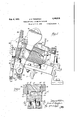
- 5 In the accompanying drawings illustrat- 45 supporting wire tightening means infina] ,position. v i 'Fig. 5, is a longitudinal sectional (VIEW on theline fil, 5 v of Fig. 3.
. Fig. 6 is a detail perspective View of the I 0 which is supported inthe mold cavity ing-a selected embodiment of the inventionfor embedment in the casting of a brake shoe. 7
i Fig. 7 is a front elevation of the mold.
Fig. 8 is a transverse sectional view on the line 88 ofFig. 5.
Fig.9 is a side elevation similar to Fig. 1, showing the mold in open position and a completed brake shoeas made in the mold. Referring to the drawings the mold comprises a drag 10 and a cope 11 having a mold cavity 12 therein adapted for casting a brake shoe. The drag isv in skeleton form and comprises a'shell 13 which is arranged in inclined position and is mounted upon supporting rails 14, which constitute the base for the mold. A drag liner 15 is removably mounted on the shell13 of the drag and it is provided with centering pins 16 adapted to enter openings 17 in the shell for positioning the drag lineron the shell. Two pairs of bolts 18 provided with nuts 19 and lock nuts 20 are arranged onthe shell to form supports for the drag liner. These bolts can be adjusted as required to properly position the drag liner with relation to the cope andalso to accommodate difi'erent'drag liners.
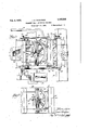
The rear end 21 of thecope forms one end of the mold cavity and it extends down to a position behind the drag liner where it is pivoted at 22 to the forwardly projecting arms 23 of the'bell crank yoke 24, which is pivoted at: 25 to the upstanding lugs 26 on the shell 18 of the drag. Parallel links 27 are pivoted at 28 at theirrear ends to the bell: crank yoke 2ft and'at 29 at their front ends to the upper ends of the bell crank levers 30 which are pivoted at 31 on the sides of the cope at the front thereof. The rear- Wardly projecting arms of the bell crank levers 30 have rounded bearing surfaces 32 arranged to engage complementary bearings 33 on the. bearing plates 34: which are fastened on the sides of the drag, being here shown conveniently bolted to the drag liner 15. Pins 35 are fixed in the copeabove the bearing arms of the bell crank levers 30, and these pins project only a short distancefrom thesides of the cope so that they Will be engaged by said arms, but "Will be cleared by the links 27 Fig.
'3). The cope can con veniently be made in skeleton form comprising a shell 36 having two sides 36 and an arched front 36", and it is adapted to receive a removable cope liner 37. The cope in arecess 41 in the cope liner. Thecope liner 87 and the drag liner 15 have the mold cavity 12 formed in their opposing faces with the parting line of the mold cavity disposed to permit the cope to be freely removed from the drag afterv the casting has beenmade. I provide tapered lugs 42 on the cope shell to engage beveled edges 43 on the drag liner, so that when the cope is lowered into position upon the drag liner the lugs on the cope shell engaging the beveled edges on'the drag liner will register the cope in proper position on the drag liner.
, The pouring gate 44 is pivoted at 45 upon the forked upper end 46 of a lever 47 which is pivoted at 48 upon lugs 49 on the drag shell 10. The lower end of this pouring gate lever is pivoted at 50 to links 51, which are also pivoted at 52 g to the lever arm 53 rigidly mounted upon the rock shaft 54'supported in ears 55 on the drag shell. A counterbalanced lever 56 is rigidly mounted on one end of the'rock shaft for operating the lever 47 'to move the pouring gate into or out of operative position relative to the drag and the cope. The rear end of the mold cavity is closed by the end 21 of the cope; the front end of the mold cavity is open to permit the molten metal to flow into the cavity'therethrough; and this open front end of. the mold cavity is covered by the pouring gate which is constructed to fitsnugly against the front ends of the drag-liner and the cope liner. The pouring cavity. 57 in the pouring gate extends downward insubstantial size and its bottom 58 is inclined when the pouring gate .is in closed position to correspond approxisand-core 59 is arranged in the cavity pouring mately with the inclination of the mold so that the molten metal will flow easily through the pouring gate into the mold cavity. A of the gate and against the ,ends of the cope liner and the drag liner. This sand core projects over a part of the end of the mold cavity and reduces the size ofthe neck which connects the sprue with the casting so that the sprue can. be easily knocked off of the casting by a comparatively light blow. This 'c'ore also protects the cope liner against the cutting action of the molten metal in pouring. I f
It is customary to embed a steel back 60 and a steel lug 61 as an insert in the back of the brake shoe casting and itis necessary to secure this insert in the cope'liner sothat it will be held in proper position for embedment. To facilitate setting in this insert and securing it in fixed position against accidental displacement I provide a looped wire 62, the ends of which are passed down through openings 63 in the cope liner and through I openings 64 in the steel back andare twisted together at65 beneath the steel back. The
loop is passed over a support 66mounted on shell and is provided with a recess 68 to. re-
cross bar'67 whiclrisTsecu'red to 'thecope,
ceive the looped wire (Fig. 8) A'tensioning device is arranged to engage the legs of the loop and it comprises a lever 69 pivoted at 70 on the cross-bar 67 and, having an operating handle 71 (Fig. 4). A detent 7 2 of any suitable construction is arranged to engage a toothed segment 73 mounted on the cope shell. The outer ends68 of the openings 63 a're enlarged to facilitateinsertion of the ends of the'wire loopinto these openings. and
the legs of the wire loop arelocatedon opposite sides of the support66 and the'crossbar 67. In initial position the lever 69 is arranged angularly to the support 66 and the cross-bar 67 and between the openings 63 so 1 that when the wire loop 62 is arranged in place the lever 69 will-project through the loop, as shown in Fig. 3. After the ends of the looped wire have been twisted together [upon the insert the tensioning lever 69 is shifted from initial position (Fig. to tensloning position (Fig. 4). The tension lever thus-produces a partial twist of the looped wire, as clearly indicated in Fig.4,
which places this wire under tension sufficient to hold the insert tightly and snugly against the cope liner. The cope liner is provided with a recess 74 to accommodate the lug 61 and also the core 75 which is inserted g in the lug to form the key opening in the attaching lug of the shoe. g
A handle lever 76 is secured by the pivot bolt 22 to the bell crank yoke 24 and is fulcrumed by the pivot bolt 25 on the drag shell.
This lever is operated to swing the cope between closed position (Fig. 1) and open posi-' tion (Fig. 9.), the opening movement being limited by a stop 77 upon which the cope rests. In Fig. 9, I have shown the brake shoe 7 8 as it appears whenit is lifted from ice the drag after themold is opened atthe con-.
clusion ofthe casting operation.
My invention provides a permanent mold of simple construction and adapted to be.
easily operated with comparatively little labor. Provisionismade forventilating the cope and the drag by exposing the parts to the atmosphere asmuch as possible so that the mold may not become over heated if continued in operationover a long-period of time. The mold is tilted atan angle to facilitate the pouringoperation and also to posi tion' the parts most advantageously for opening the mold and for securing the insert in the cope. The pivoted pouring gate provides ing gate can be swung to closed position by poourin ate to closed osition.
l a a v throwing the lever56 back over its pivot center. The pouring gate is not only pivoted to swingin an arc to and from the mold, but itis pivoted on its supporting lever so that itwill automatically adjust itself to proper position against the mold. counterbalanced .to facilitate its operation and to insure that the pouring gate will remain in snug contact with the drag and the cope liners during the casting operation. As more fully set forth in my Patent No. 1,552,247 the cope is ITIOVB'Cl initially away fromthe drag ina right line to clear the drag and the casting, and then it is swung in an arc to open position, as shown in Fig. 9. The operating handle .76 is conveniently located for swinging the cope between open and closedpositions andthe inclined position of the .mold facilitates this operation. When the cope is in open positionthe insert can be readily arranged therein and the wire engagedtherewith, and the tension means can be operated for tensioning the wire to secure the insert rigidly in place. I'provide a removable drag liner, as more fully set forth in my'Patent N 0. 1,588,209, and I also provide a removable cope line-r which may be changed like the drag liner asmay be required for making "different castings. j
. vThepouring gate lever is located on one sideof the mold and the operating lever for opening the mold islocated on the other sid'e'so that a single operator standing behind the mold can do all the things necessary to open it for removal of the casting, and this same operator standing behind the open mold can secure the insert in place in the cope for the next casting operation and lower the cope to closed position and swing the Ordinarily, however, I would provide two operators, one in a path in front of a series of molds and one in a path behind the series of molds; the first operator or the second operator may open the pouring gate, the secondoperator (will-swing the cope to open position, and
kinds of castings andthis change can be quickly made. The dragliner is held in place on the drag shell,iresting upon the adjustwhile the first operator is removing the casting the second operatorwill secure the insert in the cope. This enables the operations of the mold-to be conducted in rapid succession and without laborious eflect. The removable drag liner andthe removable cope liner prg vide for changingthe mold to make different ablesuppor-ts 18, by the pins 16, and the cope liner is secured in the cope shellby the bolts The lever v56 is 7 9 which pass through therear end piece 21 of the cope. The cope liner is held inplace upon the drag liner against lifting during the casting operation by the projection 40 at. its rear end and by the arch 36 at its front end. The sides 36 of the cope shell are secured at their rear ends to the rear end piece 21 by bolts 80. A splash shield 81, shown in Figs. 1, 5 and 9, but omitted in Fig. 7, is secured on'the frontaof the dragshell to prevent any molten metal accidentally spilled from flowing into the drag shell. The openings 63 permit the passage of the wire 62 and also provide for the escape of gases during the casting operation. A stop pin 82 on the lever arm 53 engages the links 51 to limit the forward swing of the operating lever 56 and theoutward swing of the pouring gate. A stop 83 on the pouring gate engages the forked lever to hold the pouring gate against rotative movement. H
Changes in the form, construction and ar.- rangement of parts may be made to adapt my invention for different conditionsand I reserve the right to make all such changes as fairly fall within the scope of the follow.- ing claims.
I claim:
1. A permanentrnoldfor castings and comprising a drag shell and a separate liner arranged ins aoed relation .to the shell, means engaging t e liner with the shell against lateral and longitudinal movement, and means for adjusting the liner towards and away from the shell. 7
2. A permanent mold for making castings and comprising a drag shell having "openings therein, a drag liner, pins engaged with said liner and with the openings inthe shell to removably hold the liner in place on the shell, and screw means on said shell for permitting vertical adjustment of said liner relative to said shell.
3. A permanent mold for makingcastings and comprising a drag shell and a separate liner arranged in spaced relation .to the shell, pins on one of said parts engaging the other part to center and hold the liner on the shell, and operable means on one of ,said parts engaging the other part to adju t the position of the liner relative to the shell.
4. A permanent mold for making castings and comprising a drag shell and a separate liner arranged in spa-cedrelation to the shell,
and screw adjusting means on the shell for supporting the liner and for'adjusting the position of the liner relative to the shell.
6. A permanent mold for makinglcastings and'coinprising a drag shell and a drag liner, a pair of pins on one ofsaid parts arranged to engage openings inthe other part, screws on the shell beneath and supporting the liner,
and means for adjusting said screws to adjust the position of theliner relative to the shell, said pins being located adjacent the ends of the'liner and said screws being located on opposite sides of the pins. 1
7. Apermanent mold for making castings andcomprising a drag, a cope movable relative to the drag, beveled edges on the drag, and beveled lugs on thecope to engage the beveled edges on the drag and position the cope on the drag. v f 8. A permanent mold for making castings and comprisingadrag shell, a cope shell, a removable drag liner in the drag shell, 'a removable cope liner inthe cope shell,- each of said liners containing a portion of the mold cavity and lugs integral with the copeshell and-adapted to engage the dragliner for registering the two liners when the mold is closed. a 9. A permanent mold for making castings and comprising a drag shell, a removable drag liner in the drag shell, a cope shell pivoted tothe drag shell, a removable cope liner in the cope shell and lugs integral with the cope shell and adapted to engage the drag liner for registering the two liners when the mold is closed. i Y
10., A permanent mold for making castings and comprising a cope having askeleton shell, a removable liner in said shell, said shell comprising two sides and'an end piece secured to one end of sa1d sides and integral therewith, said liner being secured at one end to said end piece, the other end of said sides and the other end of said liner being. aligned in the same plane.
11. A permanent mold for making castings and comprising a cope having a skeleton shell and a removable liner in said shell, said shell comprising two sides and an end piece secured to one end of said sides and integral therewith, said liner being secured at one end to said endpiece, and a cross piece extending across the top'of the liner and secured at its endsto the top of the sides.
12. A cope of a permanent mold for making castings and comprising a skeleton shell,
aliner, oppositely disposed ledges within the shell, and laterally projectingshoulders on the liner engaging said, ledges to removably support the liner in the shell.
13. A cope of a permanent mold for making castings and comprising a skeleton shell, a liner adapted to be inserted in said shell through one end thereof, oppositely disposed ledges Within the shell, laterally projecting pouring gate pivoted to said drag shelland shoulders onthe liner engaging said ledges and comprising a drag shell, means for supporting a drag liner in inclined position on the dragshell, a cope shell, a removable cope liner on the cope shell, means for supporting the cope shell and liner in inclined position on the drag shell and liner and an inclined located at one end thereof.v
' and comprising a drag and a relatively movable cope, a lever fulcrumed at one end onthe drag and extending alongside of the drag,
the handle and cope being pivotally connected between the operating end and the fulcrum of the handle, and means controlled by the handle for imparting tothe movable member an initial rectilinear movement relative I a 15. A permanent moldfor making castings to the fixed member followed by'a swinging movement to open the mold. a
17. A permanent mold for making cast ings and comprisinga drag and a cope having a mold cavity therein, and an inclined pouring gate arranged on one end of said cope and drag and adapted] to communicate with said mold cavity and pivotally mounted relative to the dragand thecope.
18. A permanent mold for making castings and comprising a drag and a cope having a mold cavity therein, a pouring gate arranged on one end of said cope and drag and adapted to communicate with said mold cavity and pivotally mounted on the drag, and a handle for swinging said gate about its pivot.
19. A permanent mold for making castings and comprising a drag and a cope having a pouring gate pivotally mounted on the drag andjabutti'ng one end of said drag and cope, said pouring gate covering the open end of the mold cavity and having its pouring cav ity incommunication with the mold cavity.
end of the cope and drag for swinging said pouring gate to open position or to closed position.
23. A permanent mold for making castings and comprising a drag and a cope having a mold cavity therein open at one end of the drag and cope, a pouring gate pivotally mounted at one end of the drag and adapted to be swung into abutting relation with the ends of the drag and cope to cover the open end of the mold cavity and establish communication between the pouring cavity of the gate and the mold cavity, and pivoted counterbalance means for swinging said pouring gate to open position or to closed position.
24. A permanent mold for making castings and comprising a drag and a cope having a mold cavity therein open at one end of the drag andcope, a lever pivoted at one end of themold, a pouring gate carried by said lever and abutting the ends of the drag and cope atfthe open end of the mold cavity,
said pouring gate covering the open end of V the mold cavity and having its pouring cavity incommunication with the mold cavity,
and means for operatingsaid lever.
25. A permanent mold for making castings and comprising a drag and a cope having a mold cavity therein open at one end, a pivoted lever at one end of the mold, an inclined pouring gate pivoted on said lever and abutting the ends of the drag and the cope,
, said pouring gate covering the open end of the mold cavityand having its pouring cavity in communication with the mold cavity.
26. A permanent mold for making castings and comprising a drag and a cope having a mold, cavity therein open at one end, aforked lever pivoted on the drag, a pouring gate pivoted in said forked lever and abutting the ends ofsaid drag and cope,'said "pouring gate covering the open end of the j mold .eavity and having its pouring cavity in communication with the mold cavity.
27. A permanent rnold for making castings and comprising a drag and a cope having a mold cavity therein open at one end, a pivoted lever, a pouring gate pivotally mounted on said lever and abutting the ends of the dragand cope,said pouring gate covering the open end of the mold cavity and having its pouring cavity in communication with the mold cavity, and a counterbalance lever for operating said pouring gate lever to swing the pouring gate to open position or to closed position.
28. A permanent mold for making castings and comprising a drag and a cope having a mold cavity therein open at one end, a forked lever pivotally mounted on the drag, a pouring gate pivoted in the forked lever and abutting the ends of the drag and the cope, said pouring gate covering the open end of the mold cavity and having its pouring cavity in communication with the mold cavity, a rock shaft, connections between said forked lever and said rock shaft, and a counterbalance lever on said rock shaft for operating the forked lever to swing the pouring gate into and out of operative relation to the drag and the cope. 29. A permanent mold for making castings and comprising a drag arranged in inclined position, a cope arranged in inclined position on the drag, said drag and cope having a mold cavity therein open at the high endrof the drag and cope, and an inclined, pivoted pouring gate mounted to swing into and out of operative relation to the high end of the drag and the cope and the open end of the mold cavity therein.
80. A permanent mold for making castings and comprising a drag and a cope having a mold cavity therein open at one end of the drag and cope, said end of the drag and cope being uniformly inclined, a movable pourtion between its pouring cavity and the open end of the mold cavity, and means for bodily moving said pouring gate to and away from the drag and cope.
31. A permanent mold for making castings and comprising a drag and a cope having a mold cavity therein open at one end of the drag and cope, said drag and cope being arranged in inclined position with the open end of the mold cavity elevated, a pivoted pouring gate arranged to engage the elevated end of the drag and cope to form a communication with the open end of the mold cavity, and means for swinging said pouring gate into and out of operative position relative to the drag and cope. A JAMES S. THOMPSON.
Priority Applications (2)
| Application Number | Priority Date | Filing Date | Title |
|---|---|---|---|
| US100821A US1745515A (en) | 1926-04-09 | 1926-04-09 | Permanent mold for making castings |
| US288913A US1754340A (en) | 1926-04-09 | 1928-06-28 | Insert-holding device for casting molds |
Applications Claiming Priority (1)
| Application Number | Priority Date | Filing Date | Title |
|---|---|---|---|
| US100821A US1745515A (en) | 1926-04-09 | 1926-04-09 | Permanent mold for making castings |
Publications (1)
| Publication Number | Publication Date |
|---|---|
| US1745515A true US1745515A (en) | 1930-02-04 |
Family
ID=22281706
Family Applications (1)
| Application Number | Title | Priority Date | Filing Date |
|---|---|---|---|
| US100821A Expired - Lifetime US1745515A (en) | 1926-04-09 | 1926-04-09 | Permanent mold for making castings |
Country Status (1)
| Country | Link |
|---|---|
| US (1) | US1745515A (en) |
-
1926
- 1926-04-09 US US100821A patent/US1745515A/en not_active Expired - Lifetime
Similar Documents
| Publication | Publication Date | Title |
|---|---|---|
| US2195960A (en) | Apparatus for casting metal | |
| US2581418A (en) | Machine for casting hollow articles | |
| US1745515A (en) | Permanent mold for making castings | |
| US2711568A (en) | Permanent mold apparatus for casting hollow articles | |
| US1159707A (en) | Apparatus for cleansing castings. | |
| US2483808A (en) | Casting machine | |
| US2266723A (en) | Method of and apparatus for molding | |
| US2391715A (en) | Core box | |
| US1175729A (en) | Casting-machine. | |
| US1588209A (en) | Permanent mold for making castings | |
| US1865244A (en) | Molding machine | |
| US682485A (en) | Molding apparatus. | |
| US1440923A (en) | Die-casting mold | |
| US1684715A (en) | Mold | |
| US506227A (en) | Machine for making cores for casting pipe-elbows | |
| US451276A (en) | And louis quanchi | |
| US411441A (en) | Apparatus for molding sash-weights | |
| US1286323A (en) | Machine for making stereotype printing-plates. | |
| US2772453A (en) | Foundry moulding apparatus | |
| US1373578A (en) | Core-forming device | |
| US530319A (en) | beokwith | |
| US1176726A (en) | Type-casting machine. | |
| US1331471A (en) | A corpora | |
| US1696670A (en) | Method of and machine for casting | |
| US1316666A (en) | And alfred v |