US166879A - Improvement in car-couplings - Google Patents
Improvement in car-couplings Download PDFInfo
- Publication number
- US166879A US166879A US166879DA US166879A US 166879 A US166879 A US 166879A US 166879D A US166879D A US 166879DA US 166879 A US166879 A US 166879A
- Authority
- US
- United States
- Prior art keywords
- pin
- coupling
- car
- link
- improvement
- Prior art date
- Legal status (The legal status is an assumption and is not a legal conclusion. Google has not performed a legal analysis and makes no representation as to the accuracy of the status listed.)
- Expired - Lifetime
Links
- 238000010168 coupling process Methods 0.000 title description 9
- 238000005859 coupling reaction Methods 0.000 title description 9
- 230000008878 coupling Effects 0.000 description 6
- 241000282320 Panthera leo Species 0.000 description 1
- 238000005266 casting Methods 0.000 description 1
- 238000010276 construction Methods 0.000 description 1
- 238000004519 manufacturing process Methods 0.000 description 1
- 230000000284 resting effect Effects 0.000 description 1
- 238000010626 work up procedure Methods 0.000 description 1
Images

Classifications
-
- B—PERFORMING OPERATIONS; TRANSPORTING
- B61—RAILWAYS
- B61G—COUPLINGS; DRAUGHT AND BUFFING APPLIANCES
- B61G1/00—Couplings comprising interengaging parts of different shape or form and having links, bars, pins, shackles, or hooks as coupling means
- B61G1/28—Couplings comprising interengaging parts of different shape or form and having links, bars, pins, shackles, or hooks as coupling means with vertical bolt or pin
Definitions
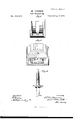
- FIG. 1 is a top plan view of the draw-head.
- Figs. 4 and 5 are front elevations of diflerent forms of draw-heads, and
- Fig. 6 is a perspective view of the coupling-pin.
- This invention is a further improvement upon the automatic car-coupling originally patented by William H. Gruver, December 22, 1874, No. 158,064, and afterward improved by Joel Miller, as shown in his patent dated June 1, 1875, No. 164,020; and it consists in the application of an improved form of coup ling-pin, and new and improved devices for supporting, guiding, and holding said pin, which greatly simplify the construction of the coupling, reduce the expense of its manufacture, and increase its durability and general efliciency.
- D represents the drawhead, provided with the usual longitudinal cavity 0, terminating at its front end ina flaring mouth B, for the purpose of causing the link to enter properly when coupling.
- each side of the interior cavity a block or lugs, A, is cast or otherwise properly secured to the inner sides of the draw-head, the proximate faces of the blocks coming so near together as just to allow suflicieut space for the easy working of the coupling-pin, and not extending down far enough to prevent the entering of the link which works in the space beneath.
- Each block is provided with a groove or recess, a, extending from the upper end of the block downward and forward nearly to the lower end; and near the upper end of said groove or recess a shoulder, 's, is formed. as shown.
- the coupling-pin P is formed in the shape of a cross, its two arms, 10 p, projecting 'into the grooves a a for the purpose of properly supporting it and guiding its movements.
- the lower end of the pin is beveled on its rear side, as seen at m, and the lower pin-hole is correspondingly beveled on its rear upper edge, as represented at a.
- the upper end of the pin extends through the upper pin-hole, and may be attached to a chain, if preferred, for convenience of operating it from-the platform of the car.
- the coupling can be efiected by hand in the ordinary manner whenever desirable, so that the invention unites in one device the ad vantages of two modes of automatic coupling, together with all the advantages of the oldfashioned link-and-pin coupling.
- Each block A may be made in one or more parts, as preferred, and the form may be varied considerably from those here shown without departing from the principles of my invention.
- the coupling-pin P having the crossarmspp, and th'e'lowe'rfen d inclined or bev-z eled at its rear edge, as shown at m, substantially as and for the purposes specified.
Landscapes
- Engineering & Computer Science (AREA)
- Mechanical Engineering (AREA)
- Emergency Lowering Means (AREA)
Description
2 Sheets--Sheet 2.
W. LANNAN. Gar-Coupling.
Patented Aug.17,1875,
Nv PHERS. PHOTO LITHO WITNESSES 2? UNITED STATES PATENT Orrron.
WILLIAM LANNAN, or UNION BRIDGE, MARYLAND.
' IMPROVEMENT lN CAR-COUPLlNGS.
Specification forming part of Letters Patent No. 166,879, dated August 17, 1875 application filed July 21, 1875. p
To all whom it may concern Be it known that 1, WILLIAM LANNAN, of Union Bridge, in the county of Carroll and State of Maryland, have invented certain new and useful Improvements in Gar-Couplings; and I do hereby declare the following to be a full, clear, and exact description of the same, reference being had to the accompanying drawings forming part of this specification, in which Figures 1 and 2 are longitudinal vertical sections, representing different modes of applying the principle of my invention. Fig. 3 is a top plan view of the draw-head. Figs. 4 and 5 are front elevations of diflerent forms of draw-heads, and Fig. 6 is a perspective view of the coupling-pin.
Similar letters of reference in the accompanying drawings denote the same parts.
This invention is a further improvement upon the automatic car-coupling originally patented by William H. Gruver, December 22, 1874, No. 158,064, and afterward improved by Joel Miller, as shown in his patent dated June 1, 1875, No. 164,020; and it consists in the application of an improved form of coup ling-pin, and new and improved devices for supporting, guiding, and holding said pin, which greatly simplify the construction of the coupling, reduce the expense of its manufacture, and increase its durability and general efliciency.
In the drawings, D represents the drawhead, provided with the usual longitudinal cavity 0, terminating at its front end ina flaring mouth B, for the purpose of causing the link to enter properly when coupling. On
each side of the interior cavity a block or lugs, A, is cast or otherwise properly secured to the inner sides of the draw-head, the proximate faces of the blocks coming so near together as just to allow suflicieut space for the easy working of the coupling-pin, and not extending down far enough to prevent the entering of the link which works in the space beneath. Each block is provided with a groove or recess, a, extending from the upper end of the block downward and forward nearly to the lower end; and near the upper end of said groove or recess a shoulder, 's, is formed. as shown. The coupling-pin P is formed in the shape of a cross, its two arms, 10 p, projecting 'into the grooves a a for the purpose of properly supporting it and guiding its movements. The lower end of the pin is beveled on its rear side, as seen at m, and the lower pin-hole is correspondingly beveled on its rear upper edge, as represented at a. The upper end of the pin extends through the upper pin-hole, and may be attached to a chain, if preferred, for convenience of operating it from-the platform of the car.
In coupling automatically with this improved device, the inner end of the link in one car is held between the lower end of the blocks A and the floor of the cavity 0, so as to present the outer end of the link properly to the opposite draw-head. As the cars come together, if the coupling-pin is down, the end of the link strikes against it and slides its inclined end m backward and upward on the incline a until the link passes under it, when the pin drops into position and the cars are coupled. If the pin, on the other hand, is up when the cars come together, being supported by its arms resting on the shoulders s s, the entering-link knocks it off of the shoulders, and it falls and couples the cars automatically. As the groove on extends forward at its lower end the pin cannot work up out of place and 'uncouple the cars accidentally, but the draft upon it work. of the link not only by the top and bottom of the draw-head, but by the side blocks A A, so that it is in little danger of giving way under any strain to which it may-be .exposed.
. The coupling can be efiected by hand in the ordinary manner whenever desirable, so that the invention unites in one device the ad vantages of two modes of automatic coupling, together with all the advantages of the oldfashioned link-and-pin coupling.
Each block A may be made in one or more parts, as preferred, and the form may be varied considerably from those here shown without departing from the principles of my invention.
In Fig. 2, where the front wall of groove 0. is formed by an independent inclined piece, the same principle is involved as in'Fig. 1. So, also, the blocks A A may be formed by tends directly to keep it down to its The pin is supported against the draft Ielaim as new simply casting projections of the proper shape or grooves of the proper shape on or ,in the side walls of the draw-head.
Having thus fully described my invention, 1. The coupling-pin P, having the crossarmspp, and th'e'lowe'rfen d inclined or bev-z eled at its rear edge, as shown at m, substantially as and for the purposes specified.
2. The blocks A, havi'ng'the grooves a a in-' olined downward and forward, in oombination purposes specified.
with the pin P, havingrcross-arms p 12, substantially as and for the pnrposesset forth.
3. The blocks A, having the grooves an,
combined with the shoulders s s at the upper end of the grooves,
and operating in combi- P, as described, for the WM. LAN NAN nation with the pin Witnesses:
JESSE H. NUSSEAR, A. L. BEARD.
Publications (1)
| Publication Number | Publication Date |
|---|---|
| US166879A true US166879A (en) | 1875-08-17 |
Family
ID=2236288
Family Applications (1)
| Application Number | Title | Priority Date | Filing Date |
|---|---|---|---|
| US166879D Expired - Lifetime US166879A (en) | Improvement in car-couplings |
Country Status (1)
| Country | Link |
|---|---|
| US (1) | US166879A (en) |
-
0
- US US166879D patent/US166879A/en not_active Expired - Lifetime
Similar Documents
| Publication | Publication Date | Title |
|---|---|---|
| US481567A (en) | Car-coupling | |
| US124430A (en) | Improvement in railway-car couplings | |
| US158975A (en) | Improvement in car-couplings | |
| US445817A (en) | Car-coupling | |
| US158064A (en) | Improvement in car-couplings | |
| US431728A (en) | Car-coupling | |
| US461065A (en) | Car-coupling | |
| US334962A (en) | Car-coupling | |
| US156806A (en) | Improvement in car-couplings | |
| US336322A (en) | Car-coupling | |
| US469540A (en) | Car-coupling | |
| US374717A (en) | Car-coupling | |
| US488078A (en) | Car-coupling | |
| US433374A (en) | Car-coupling | |
| US456858A (en) | Car-coupling | |
| US158108A (en) | Improvement in car-couplings | |
| US447165A (en) | Car-coupling | |
| US494941A (en) | Samuel c | |
| US300292A (en) | John waed | |
| US158100A (en) | Improvement in car-couplings | |
| US472418A (en) | Car-coupling | |
| US198680A (en) | Improvement in car-couplings | |
| US304847A (en) | Car-coupling | |
| US171172A (en) | Improvement in car-couplings | |
| US240238A (en) | Car-coupling |