US1663753A - Oil burner - Google Patents
Oil burner Download PDFInfo
- Publication number
- US1663753A US1663753A US144871A US14487126A US1663753A US 1663753 A US1663753 A US 1663753A US 144871 A US144871 A US 144871A US 14487126 A US14487126 A US 14487126A US 1663753 A US1663753 A US 1663753A
- Authority
- US
- United States
- Prior art keywords
- burner
- wall
- walls
- shape
- flame
- Prior art date
- Legal status (The legal status is an assumption and is not a legal conclusion. Google has not performed a legal analysis and makes no representation as to the accuracy of the status listed.)
- Expired - Lifetime
Links
- 238000002485 combustion reaction Methods 0.000 description 3
- 238000010276 construction Methods 0.000 description 3
- 238000010411 cooking Methods 0.000 description 2
- 238000009834 vaporization Methods 0.000 description 2
- 230000008016 vaporization Effects 0.000 description 2
- 241001122767 Theaceae Species 0.000 description 1
- QVGXLLKOCUKJST-UHFFFAOYSA-N atomic oxygen Chemical compound [O] QVGXLLKOCUKJST-UHFFFAOYSA-N 0.000 description 1
- 238000004140 cleaning Methods 0.000 description 1
- 230000003749 cleanliness Effects 0.000 description 1
- 239000000446 fuel Substances 0.000 description 1
- 238000010438 heat treatment Methods 0.000 description 1
- 239000007788 liquid Substances 0.000 description 1
- 239000002184 metal Substances 0.000 description 1
- 229910052760 oxygen Inorganic materials 0.000 description 1
- 239000001301 oxygen Substances 0.000 description 1
Images
Classifications
-
- F—MECHANICAL ENGINEERING; LIGHTING; HEATING; WEAPONS; BLASTING
- F23—COMBUSTION APPARATUS; COMBUSTION PROCESSES
- F23D—BURNERS
- F23D3/00—Burners using capillary action
-
- F—MECHANICAL ENGINEERING; LIGHTING; HEATING; WEAPONS; BLASTING
- F23—COMBUSTION APPARATUS; COMBUSTION PROCESSES
- F23D—BURNERS
- F23D2900/00—Special features of, or arrangements for burners using fluid fuels or solid fuels suspended in a carrier gas
- F23D2900/31016—Burners in which the gas produced in the wick is not burned instantaneously
Definitions
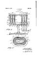
- FIG. 1 is a central longitudinal sectional view of a preferred form of multiple burner, constructed in accordance with this invention on the line 11 of Fig. 2;
- Fig. 2 is a plan of the same on a reduced scale.
- this burner can be placed in the ash pit of a heater or stove and for that reason I have provided it with a base 10 having adjusting screws 11 at the edges, preferably at three or four points, so as to adjust and level the burner within the device in'which it is installed.
- a base 10 having adjusting screws 11 at the edges, preferably at three or four points, so as to adjust and level the burner within the device in'which it is installed.
- This base supports at the center a standard 1 12 shown the form of a hollow column and threaded at the upper and lower ends.
- the upper end is mounted a support 14 of the shape which it is desired to use.
- the shape is shown as elliptical or oblong. having radiating connecting arms, between which air flows for combustion.
- each oil ring is formed 2 wlth an annular shoulder '19 and on the shoulders 17 and 19 rest perforated walls 18 and 20, constituting the walls of the burner between which the flame is guided upwardly and dispersed over a wide area on account of the nature of these walls.
- perforated walls 18 and 20 constituting the walls of the burner between which the flame is guided upwardly and dispersed over a wide area on account of the nature of these walls.
- the outside of the support 14 is an integral upwardly'extending wall 21 having a shoulder 22 in which is received an tions 25 to supply air for combustion. Also a1r passes up through the skeleton support 14 inside and outside the walls 18 and 20 to vfurnish oxygen for the various burners.
- a skeleton cover comprising no threerings 29 which are recessed to receive the tops of the several walls, 18, 20 and 23 This support is of skeleton form to e bottom for the admission of'air. 10o
- This cover has a series of upwardly projecting flanges 31 of the shape indicated in Fig. 2 which are adapted to support a tea kettle, wash boiler or cooking utensil as may be desired.
- a deflector 32 which is separate from the other parts and merely held by one of the projecting flanges 31 in which its lower part fits. It is provided with a handle 33 for use in lifting it 01f when desired.
- the outer wall of this deflector is conical as shown overlying the top of the outer burner. It is arranged to deflect the heat and flame outwardly to give a spreading eflect and utilize this burner more fully for heating the outer parts of any cooking utensil which is used on it.
- this deflector When the outer burner is to be lighted, this deflector has to be removed.
- the several burners are turned on, as many of them as may be desired, and are lighted by passing a lighted taper or match into the several spaces between the walls 18 and 20.
- the general construction and arrangement increases vaporization, prevents the vapor from escaping or burning at the inside of the inner walls 18 or the other sides of any of the Walls 20 or 23. In this manner the heat is confined in the burner so that its intensity is increased.
- the outer wall 23 keeps memes does not escape through the perforated cylam aware of the fact that the other features can be used by any person skilled in the art independently of these features without departing from the scope of the invention as expressed in the claim.
Landscapes
- Engineering & Computer Science (AREA)
- Chemical & Material Sciences (AREA)
- Combustion & Propulsion (AREA)
- Mechanical Engineering (AREA)
- General Engineering & Computer Science (AREA)
- Evaporation-Type Combustion Burners (AREA)
Description
March 27, 1928. 1,663,753
J. E. FOWLER on, BURNER Filed 00k. 28. 1926 -2 r- 5 Z P 00 D 9 a z 90 6 0 20 Z; 3. 3 331 2 2 J8 12 2 a 32 2 Z 0 3 00 2220 220000000 as: :2 Z5- Z2 I ,JJ .15 JJ L atente r. 27, 192 8.
aosnrn a. rowana, or woacns'rna,
ssacnusnrrs.
om BURNER.
Application flied October 28, 1926. Serial IEO. 144,873..
and high on the inside to prevent the escape.
of vapor and its burning on the inside of the burner and to permit burning for a long time without cleaning; to provide a construction which burns even all around the burner whether the flame is high or low; to provide an outside wall with a single row of air holes around the bottom to prevent the vapor from escaping through the perforated wall and burning on the outside and to produce a hotter flame, thereby increasing vaporization, heat and efiiciency; to provide a burner which can be placed in the ash pit of a stove in which the burner may be installed; to provide the burner with a plurality of concentric burning units; to provide a'deflector to force the flame and heat outwardly thereby spreading the heat over a larger surface; to provide a burner which may be formed either cylindrically or of elliptical shape to conform to the shape of the stove or furnace in which it may be used, and in general to provide a burner of convenient shape and construction for the principal uses referred to above and increasing the efliciency and cleanliness in the use of this class of burner.
Other objects and advantages of the invention will appear hereinafter.
Reference is to be had to the accompanying drawings in which- I Fig. 1 is a central longitudinal sectional view of a preferred form of multiple burner, constructed in accordance with this invention on the line 11 of Fig. 2; and
Fig. 2 is a plan of the same on a reduced scale.
It is to be understood that this burner can be placed in the ash pit of a heater or stove and for that reason I have provided it with a base 10 having adjusting screws 11 at the edges, preferably at three or four points, so as to adjust and level the burner within the device in'which it is installed. When used in a stove the grate is removed and this base is put in the ash pit and leveled up and adjusted to the proper height.
This base supports at the center a standard 1 12 shown the form of a hollow column and threaded at the upper and lower ends. At
the upper end is mounted a support 14 of the shape which it is desired to use. In this instance the shape is shown as elliptical or oblong. having radiating connecting arms, between which air flows for combustion.
On the support are carried a series of oil receiving rings 15 of cast metal preferably.
These are all of oblong shape in the form 5 shown, each having an inner wall projecting above the outer wall and turned inwardly and extending down vertically at a point about one-half way between the inner and outer walls and terminating in a downwardly extendin flan e havin a s uare shoulder 17. g g g q It w ll be seen that I have shown three of these 011 rings and that they are all of the same shape in this instance, namely ellipti cal, or oblong with semi-circular ends spaced equally apart and receiving liquid fuel through pipes 16. These supply pipes are all connected with a common supply pipe 13 and proper valves are provided for shutting off the entire supply or controlling the supply through each of the pipes 16.
The outer wall of each oil ring is formed 2 wlth an annular shoulder '19 and on the shoulders 17 and 19 rest perforated walls 18 and 20, constituting the walls of the burner between which the flame is guided upwardly and dispersed over a wide area on account of the nature of these walls. These walls are all of the general shape of the burner as an described above.
In the form illustrated there are three burners. 0n the outside of the support 14: is an integral upwardly'extending wall 21 having a shoulder 22 in which is received an tions 25 to supply air for combustion. Also a1r passes up through the skeleton support 14 inside and outside the walls 18 and 20 to vfurnish oxygen for the various burners.
On'the upper edges of the walls 18, 20 and 23 is supported a skeleton cover comprising no threerings 29 which are recessed to receive the tops of the several walls, 18, 20 and 23 This support is of skeleton form to e bottom for the admission of'air. 10o
and a central plate similarly recessed to receive and be supported by the inner'wall 18 and correspondingly shaped. This cover has a series of upwardly projecting flanges 31 of the shape indicated in Fig. 2 which are adapted to support a tea kettle, wash boiler or cooking utensil as may be desired.
Mounted on the next to the outer ring 29 is a deflector 32 which is separate from the other parts and merely held by one of the projecting flanges 31 in which its lower part fits. It is provided with a handle 33 for use in lifting it 01f when desired. The outer wall of this deflector is conical as shown overlying the top of the outer burner. It is arranged to deflect the heat and flame outwardly to give a spreading eflect and utilize this burner more fully for heating the outer parts of any cooking utensil which is used on it.
When the outer burner is to be lighted, this deflector has to be removed. The several burners are turned on, as many of them as may be desired, and are lighted by passing a lighted taper or match into the several spaces between the walls 18 and 20.
The general construction and arrangement increases vaporization, prevents the vapor from escaping or burning at the inside of the inner walls 18 or the other sides of any of the Walls 20 or 23. In this manner the heat is confined in the burner so that its intensity is increased. The outer wall 23 keeps memes does not escape through the perforated cylam aware of the fact that the other features can be used by any person skilled in the art independently of these features without departing from the scope of the invention as expressed in the claim.
Therefore I do not wish to be limited to the details shown, but what ll claim is lln an oil burner, the combination of an oil ring having an outer wall provided with a shoulder thereon and an inner wall extending higher than the outer wall and extending outwardly toward the outer wall and then downwardly and provided with a shoulder in its outer surface, whereby the space for the discharge of oil or flame is located at an inclination between the downwardly extending flange and the top of the outer wall, and
a pair of perforated walls supported by said shoulders for receiving the flame and products of combustion.
In testimony whereof it have hereunto aflixed my signature JUSEPH E. FUWLER.
Priority Applications (1)
| Application Number | Priority Date | Filing Date | Title |
|---|---|---|---|
| US144871A US1663753A (en) | 1926-10-28 | 1926-10-28 | Oil burner |
Applications Claiming Priority (1)
| Application Number | Priority Date | Filing Date | Title |
|---|---|---|---|
| US144871A US1663753A (en) | 1926-10-28 | 1926-10-28 | Oil burner |
Publications (1)
| Publication Number | Publication Date |
|---|---|
| US1663753A true US1663753A (en) | 1928-03-27 |
Family
ID=22510505
Family Applications (1)
| Application Number | Title | Priority Date | Filing Date |
|---|---|---|---|
| US144871A Expired - Lifetime US1663753A (en) | 1926-10-28 | 1926-10-28 | Oil burner |
Country Status (1)
| Country | Link |
|---|---|
| US (1) | US1663753A (en) |
Cited By (1)
| Publication number | Priority date | Publication date | Assignee | Title |
|---|---|---|---|---|
| US2517985A (en) * | 1948-06-22 | 1950-08-08 | Malcom A Davis | Chimney for liquid fuel burners |
-
1926
- 1926-10-28 US US144871A patent/US1663753A/en not_active Expired - Lifetime
Cited By (1)
| Publication number | Priority date | Publication date | Assignee | Title |
|---|---|---|---|---|
| US2517985A (en) * | 1948-06-22 | 1950-08-08 | Malcom A Davis | Chimney for liquid fuel burners |
Similar Documents
| Publication | Publication Date | Title |
|---|---|---|
| US2065265A (en) | Oil burner | |
| US2240571A (en) | Gas burning floor brooding hover | |
| US1663753A (en) | Oil burner | |
| US2960157A (en) | Gas burner | |
| US2187169A (en) | Stove | |
| US1864715A (en) | Heat distributor plate | |
| US1903032A (en) | Burner | |
| US2230276A (en) | Combustion apparatus | |
| US2361912A (en) | Notched pilot baffle | |
| US2361317A (en) | Burner and hot plate for gas-fired cooking apparatus | |
| US2224089A (en) | Oil burner | |
| US2088652A (en) | Gas burner and utensil support therefor | |
| US1878836A (en) | Oil burner | |
| US2376520A (en) | Burner | |
| US1703115A (en) | Fuel-combustion chamber for gas burners | |
| US2307859A (en) | Burner | |
| US136063A (en) | Improvement in lamp-stoves | |
| US1594520A (en) | Fuel-oil burner | |
| US1675842A (en) | Oil burner | |
| US1533510A (en) | Heat distributing and oxidizing utensil | |
| US1592984A (en) | Hydrocarbon burner | |
| US1707850A (en) | Oil burner | |
| US1753782A (en) | Oil-burning apparatus | |
| US1493020A (en) | Oil heater | |
| US1597027A (en) | Oil burner |