US1663151A - Stove - Google Patents
Stove Download PDFInfo
- Publication number
- US1663151A US1663151A US139154A US13915426A US1663151A US 1663151 A US1663151 A US 1663151A US 139154 A US139154 A US 139154A US 13915426 A US13915426 A US 13915426A US 1663151 A US1663151 A US 1663151A
- Authority
- US
- United States
- Prior art keywords
- bracket
- stove
- arms
- horizontal
- cross
- Prior art date
- Legal status (The legal status is an assumption and is not a legal conclusion. Google has not performed a legal analysis and makes no representation as to the accuracy of the status listed.)
- Expired - Lifetime
Links
- 229910000746 Structural steel Inorganic materials 0.000 description 5
- 238000010276 construction Methods 0.000 description 3
- 244000080575 Oxalis tetraphylla Species 0.000 description 2
- 239000011449 brick Substances 0.000 description 1
- 230000005494 condensation Effects 0.000 description 1
- 238000009833 condensation Methods 0.000 description 1
- 230000005611 electricity Effects 0.000 description 1
- JEIPFZHSYJVQDO-UHFFFAOYSA-N iron(III) oxide Inorganic materials O=[Fe]O[Fe]=O JEIPFZHSYJVQDO-UHFFFAOYSA-N 0.000 description 1
- 125000006850 spacer group Chemical group 0.000 description 1
Images

Classifications
-
- F—MECHANICAL ENGINEERING; LIGHTING; HEATING; WEAPONS; BLASTING
- F24—HEATING; RANGES; VENTILATING
- F24C—DOMESTIC STOVES OR RANGES ; DETAILS OF DOMESTIC STOVES OR RANGES, OF GENERAL APPLICATION
- F24C15/00—Details
- F24C15/08—Foundations or supports plates; Legs or pillars; Casings; Wheels
Definitions
- the present invention is an improvement in the mounting for a stove disclosed in application Serial No. 47,830 for United States Letters Patent filed by me August 3, 1925,' and it consists in the features and combina with my improved form of bracket for supporting the same. 1
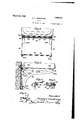
- Fig. 2 is a front viewu showing only a portion of the stove.
- Fig. '3 is a side view of Fig. 2.
- Figs. 4, 5 and 6 are detail views.
- the invention is designed to support the stove from the wall, leaving a clear space beneath.
- the supporting bracket disclosed in the application above referred to was of such construction that it was necessary to Vslit the base board vertically in order that the vertical portions of the bracket might be positioned and attached to the wall.
- brackets for strength were made of flanges with one flange fitting flat against the wall and with the lower part thereof fitting back of the baseboard. This necessitated slitting of the base board in order to accommodate the flange which extends at right angles to the one first mentioned.
- An object of the present invention is to provide such a form of lbracket as will support the stove on the wall at the proper height above the floor and while being located in large measure in the same horizontal plane with the base board, will not necessitate either the removal of the saidbase board, or the slitting of it vertically in order to accommodate the forwardly projecting flange of the bracket.
- the bracket therefore comprises a pair of members each composed of a horizontal arm 94 of angle form and curved arms 95 formed in one piece with the vert-ical flange 94a onthe arm 94 and extending downwardly and rearwardly.
- the curved arms 95 are provided with flanges 95 turned in- ⁇ wardly towards each other and bea-ring on p the face of the base board.
- Vthe rear face of the flanged bearing portion 94b is in a vertical plane-in. rear of the vertical lplane in whichv the rear faceof the bearing flanges 95a are located so that thesebearing portions respectively rest upon the wall Vand upon the face of the base board, and no special form of base board is necessary, nor is'it necessary to slit the ordinary base board. i f i The curveddownwardly extending sides 95 of the bracket are connected with the horizontal arms 94 by braces 95C, 95d.
- the pair ofk side bracket arms are connected at the rear by a. cross-bar of angle iron 97, the ends of the horizontal flange of which fit under the horizontal flanges of the arms 94 and its vertical flange rests against the front side of the vertical flanges of the arms 94.
- the angle iron cross-bar 97 fits in the rear upper corners where the flanges of bracket arms 94 'join each other.
- the side bracket arms are held together by three tie rods 99 passing through spacer tubes 98. On the rear tie rod, at each end, there is a washer 100 bearing on the inner side o-f the flanges of cross-bar 97 and holding cross-bar in place.
- the stove is preferably provided with bosses 103 extending down therefrom into openings in the horizontal flanges of the bracket arms 94, so that the stove will be held in proper position on the bracket.
- bosses 103 will'give the" advantage that in shipping or handling of the body they will afiord protection to the electric fixtures or connections on the lower face of" the stove bottom, assuming that the stove is operated by electricity.
- bracket'sidemembe-rs are formed by a stamping operation.
- each of which arms has a downward extension at its rear end of right angular form in cross section to bear on the wall7
- each side member having also an inclined arm extending from the front end of the horizontal arm rearwardly and downwardly to a point below the end of said downward extension, said inclined arms hav ing each a bearing at its lower end in advance of the vertical plane in which the rear face ot' the said downward extension lies, to rest against the face of the base board and means for securing the vbracket to the wall and to the base board, substantially as described.
- a bracket to support a stove or the like from the wall said bracket composed oit two sides, each having a horizontalarm oli angle a form in cross section withhorizontal and vertical flanges, and each having ya downwardly extending portion of right angular cross sectional i'fo1'm,'integral with the horizontal arm at its rear end, an angle iron cross piece extending between the two sides, with the horizontal flange thereof iittingunder the horizontal flanges of the horizontal arms and with its vertical flange fitting against the front face of the vertical Hangs of the rear downwardly extending portions, clips adjustable along the angle-iron cross bars for securing the bracket to the wall, a
- tie rod securing the two sidesi'together and extending along parallel with and under the horizontal flange of the angle iron cross piece7 and washers one at each end of the said tie rodlbearing on the inner sides of the ianges of the cross piece to hold the cross piece in place, substantially as described.
Landscapes
- Engineering & Computer Science (AREA)
- Chemical & Material Sciences (AREA)
- Combustion & Propulsion (AREA)
- Mechanical Engineering (AREA)
- General Engineering & Computer Science (AREA)
- Joining Of Building Structures In Genera (AREA)
Description
March 2o, 192s. 1,663,151
C. C. AARMSTRONG STOVE Filed, 9915.- 2. 1926 2 Sheets-'Sheet 1 v In il.
10o/iig'i I Chnes C'.Arm.-ffmy, um
Patented Mar. 2Q, 19218.
UNITED srATes Fries.;
CHARLES C. ARMSTRONG, 0F HUNTINGTON, WEST VIRGINIA.
s'rovn.
, Application filed Oct-ober 2, 1926. Serial No. 139,154. i
The present invention is an improvement in the mounting for a stove disclosed in application Serial No. 47,830 for United States Letters Patent filed by me August 3, 1925,' and it consists in the features and combina with my improved form of bracket for supporting the same. 1
Fig. 2 is a front viewu showing only a portion of the stove.
Fig. '3 is a side view of Fig. 2.
Figs. 4, 5 and 6 are detail views.
The invention is designed to support the stove from the wall, leaving a clear space beneath. The supporting bracket disclosed in the application above referred to was of such construction that it was necessary to Vslit the base board vertically in order that the vertical portions of the bracket might be positioned and attached to the wall.
These vertical parts or'standards of the bracket for strength were made of flanges with one flange fitting flat against the wall and with the lower part thereof fitting back of the baseboard. This necessitated slitting of the base board in order to accommodate the flange which extends at right angles to the one first mentioned.
An object of the present invention is to provide such a form of lbracket as will support the stove on the wall at the proper height above the floor and while being located in large measure in the same horizontal plane with the base board, will not necessitate either the removal of the saidbase board, or the slitting of it vertically in order to accommodate the forwardly projecting flange of the bracket.
In carrying out my present invention I have modified my previous construction by providing a bracket whose lower bearing portion will be out of the same vertical plane with the upper bearing portion so that while the upper portion finds a bearing against the wall, the lower portion will finda bearing against the front face of the base board, and no slitting of the base board will be necessary in installing the stove.
The bracket therefore comprises a pair of members each composed of a horizontal arm 94 of angle form and curved arms 95 formed in one piece with the vert-ical flange 94a onthe arm 94 and extending downwardly and rearwardly.
At their lower inner ends the curved arms 95 are provided with flanges 95 turned in-` wardly towards each other and bea-ring on p the face of the base board.
yThese flanges are;l perforated to'receive screws `for securing rthis portion of the bracket to the base board. The arms 94 at their rear ends have formed integrally therewith vertically extending flanged portions 941. These are virtually down turned in'- tegral extensions of the said arms 94, the horizontal flange of said arm becomes the vertical flange which fits against the wall and the vertical side flange of the said arm becomes the vertical side fla-ngeof the bearing portion. This bearing portion, of flanged form, is comparatively shorty and terminates at a. point above the upper edge of 4the baseboard.-` Its rear face'is outcf the same vertical plane with the rear faces of the bearing flanges 95a, that is to say,
Vthe rear face of the flanged bearing portion 94b is in a vertical plane-in. rear of the vertical lplane in whichv the rear faceof the bearing flanges 95a are located so that thesebearing portions respectively rest upon the wall Vand upon the face of the base board, and no special form of base board is necessary, nor is'it necessary to slit the ordinary base board. i f i The curveddownwardly extending sides 95 of the bracket are connected with the horizontal arms 94 by braces 95C, 95d.
The pair ofk side bracket arms are connected at the rear by a. cross-bar of angle iron 97, the ends of the horizontal flange of which fit under the horizontal flanges of the arms 94 and its vertical flange rests against the front side of the vertical flanges of the arms 94. In other words, the angle iron cross-bar 97 fits in the rear upper corners where the flanges of bracket arms 94 'join each other. The side bracket arms are held together by three tie rods 99 passing through spacer tubes 98. On the rear tie rod, at each end, there is a washer 100 bearing on the inner side o-f the flanges of cross-bar 97 and holding cross-bar in place.
On Vthis rear cross bar there are clips 102 which embrace the forward edge of'I the horizontal flange of said cross bar and have upwardly extending portions adapted to be screwed to the studding of the wall of the kitchen.
These clips are free to be moved along the rear cross bar to suit the position of the studding. It the stove is to be supported from a brick wall, expansion bolts may be used.
The stove is preferably provided with bosses 103 extending down therefrom into openings in the horizontal flanges of the bracket arms 94, so that the stove will be held in proper position on the bracket. These downwardly extending bosses will'give the" advantage that in shipping or handling of the body they will afiord protection to the electric fixtures or connections on the lower face of" the stove bottom, assuming that the stove is operated by electricity.
The reverse arrangement'might be em! ployed by having the bosses on the bracket extend up into openings in the bottom of' the stove, but this would `not possess the advantage abovementioned, but on the contrary, it
would allow moisture due to condensation within the stove to pass down onto the bracket and cause rust.
I have described the horizontal arms of the bracket sides and their downward extensions as of angle or fianged form. `This construction gives strength to the structure'like angle irontliough it will be understood that the bracket'sidemembe-rs are formed by a stamping operation.
Features relating to the stove are claimedl horizontal arm of angle iron-like iorm in cross section, each of which arms has a downward extension at its rear end of right angular form in cross section to bear on the wall7 each side member having also an inclined arm extending from the front end of the horizontal arm rearwardly and downwardly to a point below the end of said downward extension, said inclined arms hav ing each a bearing at its lower end in advance of the vertical plane in which the rear face ot' the said downward extension lies, to rest against the face of the base board and means for securing the vbracket to the wall and to the base board, substantially as described. y
2. A bracket to support a stove or the like from the wall, said bracket composed oit two sides, each having a horizontalarm oli angle a form in cross section withhorizontal and vertical flanges, and each having ya downwardly extending portion of right angular cross sectional i'fo1'm,'integral with the horizontal arm at its rear end, an angle iron cross piece extending between the two sides, with the horizontal flange thereof iittingunder the horizontal flanges of the horizontal arms and with its vertical flange fitting against the front face of the vertical Hangs of the rear downwardly extending portions, clips adjustable along the angle-iron cross bars for securing the bracket to the wall, a
tie rod securing the two sidesi'together and extending along parallel with and under the horizontal flange of the angle iron cross piece7 and washers one at each end of the said tie rodlbearing on the inner sides of the ianges of the cross piece to hold the cross piece in place, substantially as described.
In testimony whereof, I affix my signa:v ture. l i
CHARLESy c. ARMsfrnoNe.
Priority Applications (1)
| Application Number | Priority Date | Filing Date | Title |
|---|---|---|---|
| US139154A US1663151A (en) | 1926-10-02 | 1926-10-02 | Stove |
Applications Claiming Priority (1)
| Application Number | Priority Date | Filing Date | Title |
|---|---|---|---|
| US139154A US1663151A (en) | 1926-10-02 | 1926-10-02 | Stove |
Publications (1)
| Publication Number | Publication Date |
|---|---|
| US1663151A true US1663151A (en) | 1928-03-20 |
Family
ID=22485343
Family Applications (1)
| Application Number | Title | Priority Date | Filing Date |
|---|---|---|---|
| US139154A Expired - Lifetime US1663151A (en) | 1926-10-02 | 1926-10-02 | Stove |
Country Status (1)
| Country | Link |
|---|---|
| US (1) | US1663151A (en) |
Cited By (3)
| Publication number | Priority date | Publication date | Assignee | Title |
|---|---|---|---|---|
| US3068553A (en) * | 1961-06-01 | 1962-12-18 | Pittsburgh Annealing Box Compa | Method of making corrugated coil separators for annealing stacks |
| US4659044A (en) * | 1985-09-26 | 1987-04-21 | Armstrong Douglas C | Universal kit for spar-mounted mount for radar antenna |
| US6935600B1 (en) * | 2003-06-26 | 2005-08-30 | Christopher R. Barrepski | Suspension holding device and method of use |
-
1926
- 1926-10-02 US US139154A patent/US1663151A/en not_active Expired - Lifetime
Cited By (3)
| Publication number | Priority date | Publication date | Assignee | Title |
|---|---|---|---|---|
| US3068553A (en) * | 1961-06-01 | 1962-12-18 | Pittsburgh Annealing Box Compa | Method of making corrugated coil separators for annealing stacks |
| US4659044A (en) * | 1985-09-26 | 1987-04-21 | Armstrong Douglas C | Universal kit for spar-mounted mount for radar antenna |
| US6935600B1 (en) * | 2003-06-26 | 2005-08-30 | Christopher R. Barrepski | Suspension holding device and method of use |
Similar Documents
| Publication | Publication Date | Title |
|---|---|---|
| JP2021517003A5 (en) | ||
| US1663151A (en) | Stove | |
| US1727032A (en) | Shelf | |
| US2102082A (en) | Bathtub hanger | |
| US2029549A (en) | Wainscoting construction | |
| US1818814A (en) | Electrical outlet box support | |
| US2880952A (en) | Mounting structure | |
| US1997595A (en) | Acoustical ceiling construction | |
| US2973232A (en) | Multiple desk unit with combined frame and retaining rail | |
| US1887031A (en) | Radiator supporting hanger | |
| US1595643A (en) | Scaffold bracket | |
| US1630705A (en) | Radiator shield | |
| US2053987A (en) | Radiator supporting device | |
| US1105791A (en) | Means for fastening floor and sidewalk grating. | |
| GB384017A (en) | A new or improved tray for domestic stoves cooking ranges and the like | |
| US3003732A (en) | Radiator hanger | |
| GB212142A (en) | Means for attaching glass plates, and other articles, to walls | |
| US1642075A (en) | Hanger for wall radiators and the like | |
| US1266210A (en) | Support for steam-radiators. | |
| US1349894A (en) | Roof attachment | |
| US1763483A (en) | Construction cleat | |
| JP2015064144A (en) | Range food | |
| US714724A (en) | Hot-air casing for heating systems. | |
| US1577638A (en) | Bracket-hanger backing | |
| US1422177A (en) | Wall-radiator bracket |