US1652013A - Grab for lifting or hoisting - Google Patents
Grab for lifting or hoisting Download PDFInfo
- Publication number
- US1652013A US1652013A US118082A US11808226A US1652013A US 1652013 A US1652013 A US 1652013A US 118082 A US118082 A US 118082A US 11808226 A US11808226 A US 11808226A US 1652013 A US1652013 A US 1652013A
- Authority
- US
- United States
- Prior art keywords
- grab
- frame
- arms
- hoisting
- lifting
- Prior art date
- Legal status (The legal status is an assumption and is not a legal conclusion. Google has not performed a legal analysis and makes no representation as to the accuracy of the status listed.)
- Expired - Lifetime
Links
- 102000002356 Nectin Human genes 0.000 description 1
- 108060005251 Nectin Proteins 0.000 description 1
- 230000000630 rising effect Effects 0.000 description 1
- 230000002459 sustained effect Effects 0.000 description 1
- 238000004804 winding Methods 0.000 description 1
Images


Classifications
-
- B—PERFORMING OPERATIONS; TRANSPORTING
- B66—HOISTING; LIFTING; HAULING
- B66C—CRANES; LOAD-ENGAGING ELEMENTS OR DEVICES FOR CRANES, CAPSTANS, WINCHES, OR TACKLES
- B66C1/00—Load-engaging elements or devices attached to lifting or lowering gear of cranes or adapted for connection therewith for transmitting lifting forces to articles or groups of articles
- B66C1/10—Load-engaging elements or devices attached to lifting or lowering gear of cranes or adapted for connection therewith for transmitting lifting forces to articles or groups of articles by mechanical means
- B66C1/22—Rigid members, e.g. L-shaped members, with parts engaging the under surface of the loads; Crane hooks
- B66C1/28—Duplicate, e.g. pivoted, members engaging the loads from two sides
- B66C1/30—Duplicate, e.g. pivoted, members engaging the loads from two sides and also arranged to grip the sides of the loads
-
- B—PERFORMING OPERATIONS; TRANSPORTING
- B66—HOISTING; LIFTING; HAULING
- B66C—CRANES; LOAD-ENGAGING ELEMENTS OR DEVICES FOR CRANES, CAPSTANS, WINCHES, OR TACKLES
- B66C1/00—Load-engaging elements or devices attached to lifting or lowering gear of cranes or adapted for connection therewith for transmitting lifting forces to articles or groups of articles
- B66C1/10—Load-engaging elements or devices attached to lifting or lowering gear of cranes or adapted for connection therewith for transmitting lifting forces to articles or groups of articles by mechanical means
- B66C1/42—Gripping members engaging only the external or internal surfaces of the articles
- B66C1/425—Gripping members engaging only the external or internal surfaces of the articles motor actuated
-
- Y—GENERAL TAGGING OF NEW TECHNOLOGICAL DEVELOPMENTS; GENERAL TAGGING OF CROSS-SECTIONAL TECHNOLOGIES SPANNING OVER SEVERAL SECTIONS OF THE IPC; TECHNICAL SUBJECTS COVERED BY FORMER USPC CROSS-REFERENCE ART COLLECTIONS [XRACs] AND DIGESTS
- Y10—TECHNICAL SUBJECTS COVERED BY FORMER USPC
- Y10T—TECHNICAL SUBJECTS COVERED BY FORMER US CLASSIFICATION
- Y10T29/00—Metal working
- Y10T29/51—Plural diverse manufacturing apparatus including means for metal shaping or assembling
- Y10T29/5104—Type of machine
- Y10T29/5105—Drill press
- Y10T29/5107—Drilling and other
Definitions
- This invention relates to abs with mechanically operated arms or liftin and hoisting, more particularly "applicab e -for use with overhead travelling cranese 5
- the apparatus comprises a frame suspended 'by three, fouror more ropes and raised :and lowered from two ⁇ drums o'r winchesin the overhead crane, mechanically actuated grab arms to take hold of thev load which it is desired to raise orlower, and
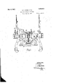
- a lFig. 1 is a ide elevationpartly in section ofhgrab suspended by four ropes.I
- ig. 2' is anend elevation of same.
- Fig. 3 isa, plan.
- Aocordingto the invention' the grab frame .A which is ⁇ built up of girders or bars a of channel, an" le or other' cross lsection issusjpended at t ree, four or ⁇ more points b by a corresponding number of ro orgrabs C may take any convenien form according to thenature of'th'e load Being.
- the frame A- carries 'two shafts. Ev one at either side upon'which two or moregrab arms() are mountedand operatedV by any convenient mechanical mechanism. ⁇ .Inthe constru ion' C are operateil y through-a rotary screw an electric motor es B from- 25,4 o e, two. or more winding or l1 ing barrels the grabs C' winch the -four s'usshown'the' grab armsA F slotte j 1de rod'cxtendm'g transversely of;V G driven by the gears anda nut- H to Whichtoggle levers I l I H are connected.
- the end la, ofthe link or lever H is -forked and pivoted to the guide arm or-lever ft2 'and the pair of links hf are lpivoted'on the guide arm' h2 and to the grab arm C the ide arms h2 bein connected 4together by a slotted link H2.
- T e lowering or raising of the nut H draws the grab arms .C together or forcesthemapart.v
- a swivelhook K may befitted to the frame A.
- 5- nut means fonadjusting the len -of the A connectingl rods tovary the reach ofthe E. PETER JOES. grab arms und an electric motor and gears J. H. LUDDLETON.
Description
Dee. e, 1927. 1,652,013
E. P. JONES. ET AL GRAB FOR LIFTING OR HOIS'ING y Filed Jue 25, 192e v s sheets-sheet 1 Dec. 6, 1927.
E. P. JONES ET AL GRAB FOR LIFTING 0R HOISTING Filed June 25, 1926 5 Sheetss-neer 2 v INVENTGRS.
. g' .pension ropes or chains B are '.'--UNI-rEDsT-Agissj PArENTf oFF1cE`-.*
. EDWARD rnrnngronns', or nLLEsnEnE ron'nAND JOHN HARRY MIDDLETON, or anLsBY, nNGLaND.
Gaan non 'Larme on n orsrrne.,
Application illed June 2 8', w26-Serial No. 118,082, and in Great Britain June 29, 1925f This invention relates to abs with mechanically operated arms or liftin and hoisting, more particularly "applicab e -for use with overhead travelling cranese 5 The apparatus comprises a frame suspended 'by three, fouror more ropes and raised :and lowered from two` drums o'r winchesin the overhead crane, mechanically actuated grab arms to take hold of thev load which it is desired to raise orlower, and
electric motor andscrew or other mechanism.
to operate the armsor tongs to take hold .-o'f `or release the load.
The invention will be fully described with reference to e accompanying drawings.' a lFig. 1 is a ide elevationpartly in section ofhgrab suspended by four ropes.I
ig. 2'is anend elevation of same. Fig. 3isa, plan. Aocordingto the invention' the grab frame .A which is `built up of girders or bars a of channel, an" le or other' cross lsection issusjpended at t ree, four or`more points b by a corresponding number of ro orgrabs C may take any convenien form according to thenature of'th'e load oben.
lifted and sustained and they maybe oper- -ated'in a variety' of Aways. i
To the upper side lof he-frame A. at 'each 40 of the four corners aswivellng shackle or eyebolt D is aiixed to attachedby which itis supended from the crane or other lifting apparatus; v v
The frame A- carries 'two shafts. Ev one at either side upon'which two or moregrab arms() are mountedand operatedV by any convenient mechanical mechanism.` .Inthe constru ion' C are operateil y through-a rotary screw an electric motor es B from- 25,4 o e, two. or more winding or l1 ing barrels the grabs C' winch the -four s'usshown'the' grab armsA F slotte j 1de rod'cxtendm'g transversely of;V G driven by the gears anda nut- H to Whichtoggle levers I l I H are connected. The end la, ofthe link or lever H is -forked and pivoted to the guide arm or-lever ft2 'and the pair of links hf are lpivoted'on the guide arm' h2 and to the grab arm C the ide arms h2 bein connected 4together by a slotted link H2. T e lowering or raising of the nut H draws the grab arms .C together or forcesthemapart.v In addition, tothe 'grab arms C, a swivelhook K may befitted to the frame A.
' What we claim as our-invention and desire.
to protect by Letters I atent'i`s 11.- A grab for hoisting or liftinghcomprising a frame, a pliirality of ro esv by which the frame is suspended, shac es ats oflmecha'nically. operated grab arms pivoted on the frame," vshafts journalled in the frame. 011 which thegrab arms are mounted,
taching the ropes to the frame, la plurality a vertical rotary screw mounted'jn the frame,-a n'ut on the screw andlugs on the nut, links to connect the nut with a' plurality of lguide arms one for eachgrab arm journalle in the frame, shafts on which the guide arms are mounted said shafts being.
arranged parallel to the grab arm pivots, a' slotted -guide rod 'extending transversely of thevgrab at each endthereofto connect opposite guide ar-ms, a air of links con' nectin each guide arm with its grab arm, a
plurahty of connecting rods -one for Seach I guide arm pivotally connecting it to a lug 'on the nut, and an electric motor and gears by which the; screw is rotated to operate the. arms.
' 2.' -A grab for hoisting or lifting, com rising ya frame, a pluralit of ro es -by W ich the frame. is'suspende shack es attaching 'the ropes to the frame, a plurality of mechanically operated-grab `arms pivotedo n the frame, shafts journalled in the frame on v which-the grab arms are mounted, a vertical rotary screw mounted in the frame, a nut on the screwand lugs onA thegnut, a plurality of, ide arms one forfeachgr'abv arm journalle in theframe, shafts en which the arran parallel to the gra'b arml pivots, a the `gra at endfthereofto connect opde arms are mounted said shafts being 10o l gg' t 1,652,013
' posite guide arms, a pair of links 'connecting by which the screw is rotated to operate thel each guide arm with its grab arm, a pluarms; rality of connecting rods one for each guide In testimony whereof We have hereunto set 10 l arm pivotally connecting -t to a, lu on the 'our hands,
5- nut, means fonadjusting the len -of the A connectingl rods tovary the reach ofthe E. PETER JOES. grab arms und an electric motor and gears J. H. LUDDLETON.
Applications Claiming Priority (1)
| Application Number | Priority Date | Filing Date | Title |
|---|---|---|---|
| GB16627/25A GB258676A (en) | 1925-06-29 | 1925-06-29 | Improvements in grabs for lifting or hoisting |
Publications (1)
| Publication Number | Publication Date |
|---|---|
| US1652013A true US1652013A (en) | 1927-12-06 |
Family
ID=10080723
Family Applications (1)
| Application Number | Title | Priority Date | Filing Date |
|---|---|---|---|
| US118082A Expired - Lifetime US1652013A (en) | 1925-06-29 | 1926-06-23 | Grab for lifting or hoisting |
Country Status (3)
| Country | Link |
|---|---|
| US (1) | US1652013A (en) |
| FR (1) | FR618709A (en) |
| GB (1) | GB258676A (en) |
Cited By (3)
| Publication number | Priority date | Publication date | Assignee | Title |
|---|---|---|---|---|
| US2946617A (en) * | 1958-06-13 | 1960-07-26 | Pan Atlantic Steamship Corp | Spreader bar |
| US3001812A (en) * | 1957-09-23 | 1961-09-26 | Heppenstall Co | Tongs |
| EP2428484A1 (en) * | 2010-09-13 | 2012-03-14 | E. Norton & Associates | Hydraulic lifting apparatus |
Families Citing this family (4)
| Publication number | Priority date | Publication date | Assignee | Title |
|---|---|---|---|---|
| US2579539A (en) * | 1947-02-03 | 1951-12-25 | Blaire Pete | Automatic pickup device |
| DE938985C (en) * | 1953-04-05 | 1956-02-09 | Maschf | Gripper for loading and stacking manure or the like. |
| US3015514A (en) * | 1956-08-24 | 1962-01-02 | Mezger Eduard | Positioning arrangement for a gripping device for moulding boxes or the like |
| CN111332941B (en) * | 2020-04-13 | 2021-08-17 | 安徽驭风风电设备有限公司 | Main beam hoisting device and method based on wind power blade |
-
1925
- 1925-06-29 GB GB16627/25A patent/GB258676A/en not_active Expired
-
1926
- 1926-06-23 US US118082A patent/US1652013A/en not_active Expired - Lifetime
- 1926-07-09 FR FR618709D patent/FR618709A/en not_active Expired
Cited By (3)
| Publication number | Priority date | Publication date | Assignee | Title |
|---|---|---|---|---|
| US3001812A (en) * | 1957-09-23 | 1961-09-26 | Heppenstall Co | Tongs |
| US2946617A (en) * | 1958-06-13 | 1960-07-26 | Pan Atlantic Steamship Corp | Spreader bar |
| EP2428484A1 (en) * | 2010-09-13 | 2012-03-14 | E. Norton & Associates | Hydraulic lifting apparatus |
Also Published As
| Publication number | Publication date |
|---|---|
| GB258676A (en) | 1926-09-29 |
| FR618709A (en) | 1927-03-18 |
Similar Documents
| Publication | Publication Date | Title |
|---|---|---|
| US1652013A (en) | Grab for lifting or hoisting | |
| US3709543A (en) | Loading crane for shipping containers of different size | |
| US1834902A (en) | Sling | |
| CN111532974A (en) | Graphite electrode lifting device | |
| US1729330A (en) | Grappling device for merchandise | |
| US1489161A (en) | Portable crane | |
| US2540803A (en) | Log carrier | |
| US1764623A (en) | Carrier | |
| US2941674A (en) | Cargo hoisting arrangements | |
| CN110510500A (en) | A kind of carbon bar shifting basket special hanger | |
| US3330590A (en) | Adjustable stabilized crane tongs | |
| CN105502145A (en) | Lifting appliance and lifting frame of PK prestressed concrete composite slab | |
| US1369963A (en) | Hoisting device | |
| US1851923A (en) | Tongs | |
| US1551886A (en) | Sling | |
| US1472081A (en) | Grapple | |
| US2994554A (en) | Tongs | |
| SU850551A1 (en) | Crossbeam for lifting and tipping large articles | |
| GB598580A (en) | Improvements in cargo hoists | |
| US1357429A (en) | Hoisting mechanism for overhead traveling cranes | |
| JP2015189542A (en) | quay crane | |
| US3868138A (en) | Hoisting means for handling and lifting objects, such as timer stacked to form load units | |
| US1727942A (en) | Truck hoist | |
| SU652084A1 (en) | Load-hoisting device for erecting structures with two cranes | |
| US1811429A (en) | Brick stack carrier |