US1640407A - Automatic lubricating cup - Google Patents
Automatic lubricating cup Download PDFInfo
- Publication number
- US1640407A US1640407A US112315A US11231526A US1640407A US 1640407 A US1640407 A US 1640407A US 112315 A US112315 A US 112315A US 11231526 A US11231526 A US 11231526A US 1640407 A US1640407 A US 1640407A
- Authority
- US
- United States
- Prior art keywords
- cup
- screw
- shaft
- spring
- oil
- Prior art date
- Legal status (The legal status is an assumption and is not a legal conclusion. Google has not performed a legal analysis and makes no representation as to the accuracy of the status listed.)
- Expired - Lifetime
Links
- 230000001050 lubricating effect Effects 0.000 title description 5
- 208000028659 discharge Diseases 0.000 description 4
- 239000000314 lubricant Substances 0.000 description 4
- 238000004804 winding Methods 0.000 description 3
- 238000010276 construction Methods 0.000 description 2
- 230000001105 regulatory effect Effects 0.000 description 2
- 241000969130 Atthis Species 0.000 description 1
- 241000905957 Channa melasoma Species 0.000 description 1
- WJDOMTAMQVNRCX-OBJOEFQTSA-N Isopolygonal Natural products C1=C(C=O)[C@@H](O)C[C@H]2C(C)(C)CCC[C@]21C WJDOMTAMQVNRCX-OBJOEFQTSA-N 0.000 description 1
- WJDOMTAMQVNRCX-DYEKYZERSA-N Polygonal Natural products C1=C(C=O)[C@H](O)C[C@H]2C(C)(C)CCC[C@]21C WJDOMTAMQVNRCX-DYEKYZERSA-N 0.000 description 1
- 230000008878 coupling Effects 0.000 description 1
- 238000010168 coupling process Methods 0.000 description 1
- 238000005859 coupling reaction Methods 0.000 description 1
- 239000012530 fluid Substances 0.000 description 1
- 239000010985 leather Substances 0.000 description 1
- 238000004519 manufacturing process Methods 0.000 description 1
- 239000002184 metal Substances 0.000 description 1
- 238000012856 packing Methods 0.000 description 1
Images
Classifications
-
- F—MECHANICAL ENGINEERING; LIGHTING; HEATING; WEAPONS; BLASTING
- F16—ENGINEERING ELEMENTS AND UNITS; GENERAL MEASURES FOR PRODUCING AND MAINTAINING EFFECTIVE FUNCTIONING OF MACHINES OR INSTALLATIONS; THERMAL INSULATION IN GENERAL
- F16N—LUBRICATING
- F16N7/00—Arrangements for supplying oil or unspecified lubricant from a stationary reservoir or the equivalent in or on the machine or member to be lubricated
-
- F—MECHANICAL ENGINEERING; LIGHTING; HEATING; WEAPONS; BLASTING
- F16—ENGINEERING ELEMENTS AND UNITS; GENERAL MEASURES FOR PRODUCING AND MAINTAINING EFFECTIVE FUNCTIONING OF MACHINES OR INSTALLATIONS; THERMAL INSULATION IN GENERAL
- F16N—LUBRICATING
- F16N3/00—Devices for supplying lubricant by manual action
- F16N3/02—Devices for supplying lubricant by manual action delivering oil
- F16N3/04—Oil cans; Oil syringes
- F16N3/08—Oil cans; Oil syringes incorporating a piston-pump
Definitions
- This invention relates to an improved automatically oiling or lubricating cup for shafts, bearings, journal boxes, and various kinds of machine elements, although the same is especially adapted for use upon automobiles to replace the various kinds of oil cups now employed.
- My principal aim is to provide a simple and inexpensive structure of this class wherein a continuous oil supply isinsured, the action being such that the oil feed is comparatively slow, and not unduly under such pressure as would tend to squeeze the oil out of the lubricated parts as is frequently the case with the cups now in use.
- the invention comprises an open top cup adapted to contain the lubricant, this cup being provided with a screw threaded neck adapted to tap into a screw threaded opening in the part to be lubricated.
- a screw threaded neck adapted to tap into a screw threaded opening in the part to be lubricated.
- Aremov'able cover is provided for the open top and it car 168) a clock sprin a winding device therefor, and a. feed screw on which the ejecting plunger operates. Then there is a novel flow control device associated with the screw threaded neck at the bottom and the lower end of the feed screw where by a slow speed of the oil is insured.
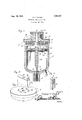
- Figure 1 is a view in section and elevation of a complete oiling device constructed in accordance with the present invention.
- Figure 2 is a perspective view of the winding block.
- Figure 3 is a perspective view of the top of the removable cover.
- Figure 4 is a perspective view of the which is adapted to bethreaded into an -.rev. socket 14: formed in the top of the flow con- 1926. Serial No. 112,315.
- the removable cover is designated generally by the reference character 1- and this comprises a circular top plate 5 having a depending screw threaded skirt 6 threaded onto the upper nd of the body of the cup.
- This skirt is also internally screw threaded above the top of the cup in order to permit a disk 7 to be fitted into it and this disk is arranged in spaced relation to the top plate 5 in order to form a housing for a clock spring 8.
- the spring is anchored at its inner end as at 9 to the shaft 10. Then too, it is anchored at its opposite end as at 11 to the l? removable cover.
- It is an ordinary clock spring of the flat resilient type, and obviously when it is WOUDCl up it tends to rotate the shaft 1O.v It might be stated,
- a plunger 17 mounted on its under side with a leather packing element '18. This in held in place by metal washers 19 and retaining screws 20, and itprovides a fluid tight joint with the wall of-the cup.
- the wall is providcd'with a vertical groove 21 and the plunger carries a removable stud 22 which operates slidably in this groove and prevents rotation of the plunger.
- a block 23 is fastened to the upper extended end of the shaft and this carries a spring pressed pawl 24 adapted to be selectively and succcs sively seated in ratchet seats 25 formed in the top plates 5.
- the pawl is provided at its top with a small handle 26 which may be seated in a notch 27 formed in one end portion of the block.
- the flat spring is wound up and this is accomplished by grasping the block 23 and turning it in an obvious manner, the pawl and ratchet mechanism serving at this time to retain the spring as it is gradually wound.
- the cup is filled with oil and that the piston is at the top of the cylinder or cup as shown and that the feed plug 15 is threaded all the way down into the neck 2, it will be seen that upon lifting up on the latch of pawl 24, and turning it to the position shown in Figure 2, it will be held disengaged from the ratchet seats.
- the spring will be free to rotate the shaft and in so doing itwill feed the-plunger 17 downwardly and at the same time screw or feed the plug 15 upwardly, thus providing a larger discharge passage as the oil is ejected from the cup and through the groove 16.
- an open top cup adapted to contain a lubricant, said cup being provided with a screw threaded neck adapted to cap into a screw. threa led opening in the part to be lubricated, a removable cover for said open top, a clock spring carried by said cover, a feed screw having a cylindrical portionrotatably connected with said cap, having an intermediate screw threaded portion, and
- said spring means being associated with said cap and screw, an ejecting plunger on the screw threaded portion of the screw, and a screw threaded plug fitted into said neck and provided with an oil dis charge port and a socket receiving the polyg onal reduced end portion of said screw.
- an open top cup a removable closure for the open top, spring means carried by said closure, a shaft rotatably connected with said closure, said spring means being connected with said shaft, a winding device cooperable with said shaft, said shaft being provided with an internal intermediate screw threaded portion, an ejecting plunger threaded upon said portion, and a flow control device at,
Landscapes
- Engineering & Computer Science (AREA)
- General Engineering & Computer Science (AREA)
- Mechanical Engineering (AREA)
- Chemical & Material Sciences (AREA)
- Oil, Petroleum & Natural Gas (AREA)
- Closures For Containers (AREA)
Description
Aug. 30, 1927. I
G. F. HERBST AUTOMAT-IC LUBRICATIENG CUP Filed May 28. 1926 Patented An. 30, 1927.
GEORGE HERBST, OF UNDERI-IILL, WISCONSIN.
AUTOMATIC LUBRICATING CUP.
Application filed May 28,
This invention relates to an improved automatically oiling or lubricating cup for shafts, bearings, journal boxes, and various kinds of machine elements, although the same is especially adapted for use upon automobiles to replace the various kinds of oil cups now employed.
My principal aim is to provide a simple and inexpensive structure of this class wherein a continuous oil supply isinsured, the action being such that the oil feed is comparatively slow, and not unduly under such pressure as would tend to squeeze the oil out of the lubricated parts as is frequently the case with the cups now in use.
Briefly, the invention comprises an open top cup adapted to contain the lubricant, this cup being provided with a screw threaded neck adapted to tap into a screw threaded opening in the part to be lubricated. Aremov'able cover is provided for the open top and it car 168) a clock sprin a winding device therefor, and a. feed screw on which the ejecting plunger operates. Then there is a novel flow control device associated with the screw threaded neck at the bottom and the lower end of the feed screw where by a slow speed of the oil is insured.
- It follows, of course, that one of the outstanding objects is to provide novel details for carrying out the above features and advantages, these details being arranged in a compact and convenient manner which insures the production of a practical and pos itive device assuring eiiicient results.
'Gther features, advantages, and objects will become apparent from the following descri tion and drawing.
In the accompanying drawing forming a part of this application and in which like numerals are employed to designate like, parts throughout the same: v
Figure 1 is a view in section and elevation of a complete oiling device constructed in accordance with the present invention.
Figure 2 is a perspective view of the winding block.
Figure 3 is a perspective view of the top of the removable cover.
Figure 4: is a perspective view of the which is adapted to bethreaded into an -.rev. socket 14: formed in the top of the flow con- 1926. Serial No. 112,315.
opening in the part to be lubricated. This neck is also internally screw threaded for a purpose to be hereinafter made plain. Then too, in the bottom of the cup is a screw'threaded hole which is adapted to accommodate a removable plug 3 of suitable construction intended to serve as a coupling for a supply pump. It vis understood that the construction of the plug is immaterial and the Tocation of the hole may be at any appropriate point. The removable cover is designated generally by the reference character 1- and this comprises a circular top plate 5 having a depending screw threaded skirt 6 threaded onto the upper nd of the body of the cup. This skirt is also internally screw threaded above the top of the cup in order to permit a disk 7 to be fitted into it and this disk is arranged in spaced relation to the top plate 5 in order to form a housing for a clock spring 8. The spring is anchored at its inner end as at 9 to the shaft 10. Then too, it is anchored at its opposite end as at 11 to the l? removable cover. It is an ordinary clock spring of the flat resilient type, and obviously when it is WOUDCl up it tends to rotate the shaft 1O.v It might be stated,
here that a portion of the shaft in the cup is provided with threads 12 forming a feed screw. The lower end of the shaft is reduced in diameter as at 13 and made into rectangular cross section, thus providing a This key extends into a polygonal trol plug 15. This plug is threaded into the 1nterior of the neck 2 and is provided in one side with an Oil discharge groove 16.
Atthis time I would direct attention to Figure 4t where n it will be seen that thegroove is comparatively shallow and narrow at its top and gradually increased in width and depth toward its bottom. It will thus be seen that the plug is a compensating device and the action of the same with its groove 16 is to permit the outflowing lub icant to have the same pressure at the. end of the plunger stroke, regardless of the weakenedtension of the spring at this part of the stroke.
Mounted on the threads on the shaftis a plunger 17 provided on its under side with a leather packing element '18. This in held in place by metal washers 19 and retaining screws 20, and itprovides a fluid tight joint with the wall of-the cup. It will be noted that the wall is providcd'with a vertical groove 21 and the plunger carries a removable stud 22 which operates slidably in this groove and prevents rotation of the plunger. Thus when the shaft is rotated the plunger is fed downwardly to forcibly eject the oil,
I It is yet to be pointed out that a block 23 is fastened to the upper extended end of the shaft and this carries a spring pressed pawl 24 adapted to be selectively and succcs sively seated in ratchet seats 25 formed in the top plates 5. The pawl is provided at its top with a small handle 26 which may be seated in a notch 27 formed in one end portion of the block.
The operation of the device is as follows. First, the flat spring is wound up and this is accomplished by grasping the block 23 and turning it in an obvious manner, the pawl and ratchet mechanism serving at this time to retain the spring as it is gradually wound. Assuming then that the cup is filled with oil and that the piston is at the top of the cylinder or cup as shown and that the feed plug 15 is threaded all the way down into the neck 2, it will be seen that upon lifting up on the latch of pawl 24, and turning it to the position shown in Figure 2, it will be held disengaged from the ratchet seats. Then the spring will be free to rotate the shaft and in so doing itwill feed the-plunger 17 downwardly and at the same time screw or feed the plug 15 upwardly, thus providing a larger discharge passage as the oil is ejected from the cup and through the groove 16.
It is believed that by considering the detailed description and the operation in connection with the disclosure made in the drawings, a clear understanding of the invention will be had. Therefore, a more lengthy description is thought unnecessary.
Minor changes coming within the field of invention claimed may be resorted to if desired.
Having thus described the invention, what I claim as new and desire to secure by Letters Patent is:
1. In a lubricating device of the class described, a lubricant containing cup having a discharge neck at its bottom, a regulating into said neck and provided with an oil con-,
ducting groove and a polygonal socket, a shaft mounted for rotation in said cup, sald shaft being provided with screw threads and with a polygonal portion slidably received in said socket, a plunger threaded on said screw threaded portion, spring means connected with the shaft and with the cup for automatically rotating the shaft, and manu ally operable means for rotating the shaft in a direction to wind the spring.
3. In a lubricating device of the class described, an open top cup adapted to contain a lubricant, said cup being provided with a screw threaded neck adapted to cap into a screw. threa led opening in the part to be lubricated, a removable cover for said open top, a clock spring carried by said cover, a feed screw having a cylindrical portionrotatably connected with said cap, having an intermediate screw threaded portion, and
having a reduced lower end portion of polyg- I onal cross sections, said spring means being associated with said cap and screw, an ejecting plunger on the screw threaded portion of the screw, and a screw threaded plug fitted into said neck and provided with an oil dis charge port and a socket receiving the polyg onal reduced end portion of said screw.
4. In a structure of the class described, an open top cup, a removable closure for the open top, spring means carried by said closure, a shaft rotatably connected with said closure, said spring means being connected with said shaft, a winding device cooperable with said shaft, said shaft being provided with an internal intermediate screw threaded portion, an ejecting plunger threaded upon said portion, and a flow control device at,
the bottom of the cup operated by said screw for regulating the discharge of lubricant from the cup.
In testimony whereof I afiix my signature.
GEORGE I HEBBST;
Priority Applications (1)
| Application Number | Priority Date | Filing Date | Title |
|---|---|---|---|
| US112315A US1640407A (en) | 1926-05-28 | 1926-05-28 | Automatic lubricating cup |
Applications Claiming Priority (1)
| Application Number | Priority Date | Filing Date | Title |
|---|---|---|---|
| US112315A US1640407A (en) | 1926-05-28 | 1926-05-28 | Automatic lubricating cup |
Publications (1)
| Publication Number | Publication Date |
|---|---|
| US1640407A true US1640407A (en) | 1927-08-30 |
Family
ID=22343230
Family Applications (1)
| Application Number | Title | Priority Date | Filing Date |
|---|---|---|---|
| US112315A Expired - Lifetime US1640407A (en) | 1926-05-28 | 1926-05-28 | Automatic lubricating cup |
Country Status (1)
| Country | Link |
|---|---|
| US (1) | US1640407A (en) |
Cited By (3)
| Publication number | Priority date | Publication date | Assignee | Title |
|---|---|---|---|---|
| US2985256A (en) * | 1957-10-02 | 1961-05-23 | Joseph E Hauser | Grease cup |
| US4799574A (en) * | 1986-06-25 | 1989-01-24 | Skf Industrial Trading & Development Co. B.V. | Lubrication device |
| US20030037995A1 (en) * | 2000-03-21 | 2003-02-27 | Patterson Denis Arthur John | Lubricating device |
-
1926
- 1926-05-28 US US112315A patent/US1640407A/en not_active Expired - Lifetime
Cited By (4)
| Publication number | Priority date | Publication date | Assignee | Title |
|---|---|---|---|---|
| US2985256A (en) * | 1957-10-02 | 1961-05-23 | Joseph E Hauser | Grease cup |
| US4799574A (en) * | 1986-06-25 | 1989-01-24 | Skf Industrial Trading & Development Co. B.V. | Lubrication device |
| US20030037995A1 (en) * | 2000-03-21 | 2003-02-27 | Patterson Denis Arthur John | Lubricating device |
| US6802394B2 (en) * | 2000-03-21 | 2004-10-12 | Wymark Limited | Lubricating device |
Similar Documents
| Publication | Publication Date | Title |
|---|---|---|
| US1640407A (en) | Automatic lubricating cup | |
| US1303845A (en) | Oil-caw | |
| US1561308A (en) | Vacuum-feed lubricating device | |
| US1770036A (en) | Lubricating device | |
| US1784573A (en) | Grease cup | |
| US1393097A (en) | Grease-cup | |
| US2134622A (en) | Grease pump | |
| US332623A (en) | Lubricator | |
| US1283841A (en) | Lubricator. | |
| US773829A (en) | Oil-cup. | |
| US1604756A (en) | Lubricator | |
| US1648228A (en) | Lubricating grease cup | |
| US380659A (en) | Charles h | |
| US1387473A (en) | Receptacle for containing and discharging semisolid and pasty substances | |
| US1448595A (en) | Compression grease cup and container | |
| US1353171A (en) | Grease-cup | |
| US1003305A (en) | Grease-cup. | |
| US1364464A (en) | Eugene joseph timerman | |
| US1461665A (en) | Grease cup | |
| US612736A (en) | Lubricator | |
| US1596359A (en) | Grease cup | |
| US1165424A (en) | Automatic grease-cup. | |
| US915937A (en) | Lubricator. | |
| US1547006A (en) | Automatically-operated grease cup | |
| US1357082A (en) | Automatic gbease-ctjp |