US1591702A - Belt buckle - Google Patents
Belt buckle Download PDFInfo
- Publication number
- US1591702A US1591702A US1591702DA US1591702A US 1591702 A US1591702 A US 1591702A US 1591702D A US1591702D A US 1591702DA US 1591702 A US1591702 A US 1591702A
- Authority
- US
- United States
- Prior art keywords
- belt
- gripping member
- buckle
- face plate
- flanges
- Prior art date
- Legal status (The legal status is an assumption and is not a legal conclusion. Google has not performed a legal analysis and makes no representation as to the accuracy of the status listed.)
- Expired - Lifetime
Links
- 238000010276 construction Methods 0.000 description 6
- 230000004075 alteration Effects 0.000 description 1
- 239000002184 metal Substances 0.000 description 1
- 230000004048 modification Effects 0.000 description 1
- 238000012986 modification Methods 0.000 description 1
Images
Classifications
-
- A—HUMAN NECESSITIES
- A44—HABERDASHERY; JEWELLERY
- A44B—BUTTONS, PINS, BUCKLES, SLIDE FASTENERS, OR THE LIKE
- A44B11/00—Buckles; Similar fasteners for interconnecting straps or the like, e.g. for safety belts
- A44B11/02—Buckles; Similar fasteners for interconnecting straps or the like, e.g. for safety belts frictionally engaging surface of straps
- A44B11/06—Buckles; Similar fasteners for interconnecting straps or the like, e.g. for safety belts frictionally engaging surface of straps with clamping devices
- A44B11/12—Buckles; Similar fasteners for interconnecting straps or the like, e.g. for safety belts frictionally engaging surface of straps with clamping devices turnable clamp
-
- Y—GENERAL TAGGING OF NEW TECHNOLOGICAL DEVELOPMENTS; GENERAL TAGGING OF CROSS-SECTIONAL TECHNOLOGIES SPANNING OVER SEVERAL SECTIONS OF THE IPC; TECHNICAL SUBJECTS COVERED BY FORMER USPC CROSS-REFERENCE ART COLLECTIONS [XRACs] AND DIGESTS
- Y10—TECHNICAL SUBJECTS COVERED BY FORMER USPC
- Y10T—TECHNICAL SUBJECTS COVERED BY FORMER US CLASSIFICATION
- Y10T24/00—Buckles, buttons, clasps, etc.
- Y10T24/40—Buckles
- Y10T24/4072—Pivoted lever
Definitions
- the invention relates to buckles and more particularly to belt buckles.
- a further object aims at the provision of a buckle of the characterdescribed which is of extremely simple construction but nevertheless characterized by a high degree of efficiency.
- Another object aims at mounting the releasing member for reciprocation so that back and forth movements thereof respectively place the gripping member in and out of functional position.
- a still further object constitutes the con struction and arrangement of the gripping and releasing members so that a slight movement of the releasing member will entail a comparatively large movement of the gripper member and therewith a quick release or gripping of the belt end received between the flanges. It is a further object to arrange the gripping member to one side of the transverse center of the buckle so that the active end of the gripper cooperates with a downward slope of the face plate and thus the gripping of the belt end is heightened.
- Another object constitutes the provision of a gripping member which is of integral construction and adapted to function equally well with belts of varying thicknesses.
- the invention also includes as a further object certain features of construction and arrangement tending to enhance the usefulness and reliability of a device of this character.
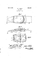
- Fig. 1 is a top plan View of the buckle constructed in accordance with my invention.
- Fig. 2 is a side view of the buckle.
- Fig. 3 is a bottom plan View thereof.
- Figs. 4 and 5 are respectively front and end views of the gripping member.
- the buckle generally designated by 10 comprises a face plate 11 which at the center is formed with a raised portion 12.
- the face plate is curved in longitudinal direction to' conform to the waist-line of a person and the raised portion gradually merges into the general contour of the face plate.
- From the sides of the face plate and at right angles thereto extend flanges 13 and 14 which are bent inwardly at right angles to provide guide ledges 15 and 16 for a purpose hereinafter referred to.
- the flanges and their guide ledges define with the inner side of the face a chamber in which all operative parts of the buckle and the belt end are received so that the belt buckle presents a compact appearance I and as no parts protrude the buckle closely adheres to the waist line with out any discomfort to the wearer.
- a gripping member generally designated by 18 is pivotally secured in the flanges 13 and 14.
- the gripping member 18 is made of a single piece of metal which is formed to provide asleeve portion 19.
- the latter forms an integral part of a pair of wings 20 and 21 longer than the sleeve and terminating in convexly curved edges 22 and 23.
- the wing 20 is slightly higher than the companion wing so that the edges 22 and 23 are in different planes.
- the wing 20 is formed at the ends of edge 22 with lugs 24 and both wings 20 and 21 have-at the lower end and parallel with the sleeve 19 lugs 25.
- Each pair of lugs 25 constitutes a pivot pin and outer apertures 26 provided in transverse registry in the flanges 13 and 14 and to one side of center 17.
- the gripping member 18 is so arranged that the wings 20 and 21 are opposed to the face plate while the sleeve 19 is proximate to the guide ledges 15 and 16.
- a A releasing member 27 of approximately rectangular form is pivotally secured to the gripping member by extending with a transverse web 28 through the sleeve 19.
- the releasing member is formed with an intermediate web 29 defining a rectangular opening 30 and a narrow slot 31.
- the wings of the gripping member are turned clockwise and conversely upon pushing the releasing member, the gripping member is arranged horizontally as shown in dotted lines in Fi 2, in which position the gripper member releases.
- one end 33 of a belt 36 is looped through the slot 31 and secured to the body port-ion of the belt by a fastener 34 of any desired construction.
- the other end 35 of the belt is introduced at the other side of the buckle between the flanges 13 and 1 1.
- the gripping member engages the belt end 35 and forces the same against the face plate in tight engagement therewith.
- Attention is called to the fact that the edges of the gripping member cooperate with a downwardly sloping portion 37 of the face plate so that great functional engagement is ensured between the face plate, belt and gripping member.
- the construction of the gripping member as a double lever with the fulcrum farther removed from the edges than from the sleeve entails quick release and speedy arrangement in functional position.
- the gripping member has its edges 22 and 23 in different planes belts of varying thicknesses may be employed with the same buckle. In case of a thick belt the shorter wing 21 will engage the belt while the edge 22 will engage a thin belt.
- the lugs 24 are provided, which engagingthe face plate arrest further movement of said member.
- the guide ledges 15 and 16 ensure the reciprocating movements of the releasing member 27. They form together with the face plate and side flanges a casing in which the operative parts of the buckle and the belt are received, there being no parts protruding from the casing.
- a gripping member for buckles comprising a pair of contacting plates having lugs in the plate planes at the lower end constituting pivot pins, said plates terminating in convex upper edges provided at the ends with upstanding lugs, and a sleeve uniting said plates and having its axis in the plane of contact of said plates said plates, said lugs, and said sleeve being formed integral.
- a belt buckle comprising a main body portion having a face plate portion provided with a concavo convex central part, a pair of side flanges, a gripping member journaled in said side flanges, reciprocating means pivotally secured to said gripping member for actuating the latter, and means integral with said gripping member and cooperating with an incline of the raised part of said face plate for limiting the rotary movement of said gripping member.
Landscapes
- Buckles (AREA)
Description
July 6, 1926.
w. P. GISSKE BELT BUCKLE Filed April 4. 1925 awwgiiiii E ATTORNEY. i
Patented July 6, 1926.
UNITED STATES WALTER P. GISSKE, OF CHICAGO, ILLINOIS.
BELT BUCKLE.
Application filed April 4, 1923. Serial No. 629,942.
The invention relates to buckles and more particularly to belt buckles.
It is an object of the invention to provide a self locking buckle which comprises a body portion having a face plate and a pair of side flanges between which one end of the belt is received and in which a gripping member is pivotally secured, there be ing a releasing member pivotally secured to said gripper member for releasing the letter.
A further object aims at the provision of a buckle of the characterdescribed which is of extremely simple construction but nevertheless characterized by a high degree of efficiency.
Another object aims at mounting the releasing member for reciprocation so that back and forth movements thereof respectively place the gripping member in and out of functional position.
A still further object constitutes the con struction and arrangement of the gripping and releasing members so that a slight movement of the releasing member will entail a comparatively large movement of the gripper member and therewith a quick release or gripping of the belt end received between the flanges. It is a further object to arrange the gripping member to one side of the transverse center of the buckle so that the active end of the gripper cooperates with a downward slope of the face plate and thus the gripping of the belt end is heightened.
Another object constitutes the provision of a gripping member which is of integral construction and adapted to function equally well with belts of varying thicknesses.
It is also an object of the invention to provide a buckle in which no parts protrude beyond the outer edges of the side flanges, so that the buckle which is of arcuate form is compact and conforms to the body of the wearer and is in nested relation thereto.
The invention also includes as a further object certain features of construction and arrangement tending to enhance the usefulness and reliability of a device of this character.
To the accomplishment of the objects stated and others that will become apparent upon perusal of the following description of the invention, the latter comprises the means described in the specification particularly pointed out in the claims forming a part thereof and illustrated in the drawing in which:
Fig. 1 is a top plan View of the buckle constructed in accordance with my invention.
Fig. 2 is a side view of the buckle.
Fig. 3 is a bottom plan View thereof.
Figs. 4 and 5 are respectively front and end views of the gripping member.
The buckle generally designated by 10 comprises a face plate 11 which at the center is formed with a raised portion 12. The face plate is curved in longitudinal direction to' conform to the waist-line of a person and the raised portion gradually merges into the general contour of the face plate. From the sides of the face plate and at right angles thereto extend flanges 13 and 14 which are bent inwardly at right angles to provide guide ledges 15 and 16 for a purpose hereinafter referred to. The flanges and their guide ledges define with the inner side of the face a chamber in which all operative parts of the buckle and the belt end are received so that the belt buckle presents a compact appearance I and as no parts protrude the buckle closely adheres to the waist line with out any discomfort to the wearer.
To one side of the transverse center-17 a gripping member generally designated by 18 is pivotally secured in the flanges 13 and 14. As shown in Figs. 4 and 5 the gripping member 18 is made of a single piece of metal which is formed to provide asleeve portion 19. The latter forms an integral part of a pair of wings 20 and 21 longer than the sleeve and terminating in convexly curved edges 22 and 23. The wing 20 is slightly higher than the companion wing so that the edges 22 and 23 are in different planes.
The wing 20 is formed at the ends of edge 22 with lugs 24 and both wings 20 and 21 have-at the lower end and parallel with the sleeve 19 lugs 25. Each pair of lugs 25 constitutes a pivot pin and outer apertures 26 provided in transverse registry in the flanges 13 and 14 and to one side of center 17. As appears in Fig. 2 the gripping member 18 is so arranged that the wings 20 and 21 are opposed to the face plate while the sleeve 19 is proximate to the guide ledges 15 and 16. A A releasing member 27 of approximately rectangular form is pivotally secured to the gripping member by extending with a transverse web 28 through the sleeve 19. The releasing member is formed with an intermediate web 29 defining a rectangular opening 30 and a narrow slot 31. Upon a pull being exert-ed upon the releasing member in the direction of the arrow 32 the wings of the gripping member are turned clockwise and conversely upon pushing the releasing member, the gripping member is arranged horizontally as shown in dotted lines in Fi 2, in which position the gripper member releases.
In use one end 33 of a belt 36 is looped through the slot 31 and secured to the body port-ion of the belt by a fastener 34 of any desired construction. The other end 35 of the belt is introduced at the other side of the buckle between the flanges 13 and 1 1. Upon the belt end 33 being pulled the gripping member engages the belt end 35 and forces the same against the face plate in tight engagement therewith. Attention is called to the fact that the edges of the gripping member cooperate with a downwardly sloping portion 37 of the face plate so that great functional engagement is ensured between the face plate, belt and gripping member. Furthermore, the construction of the gripping member as a double lever with the fulcrum farther removed from the edges than from the sleeve entails quick release and speedy arrangement in functional position.
In view of the fact that the gripping member has its edges 22 and 23 in different planes belts of varying thicknesses may be employed with the same buckle. In case of a thick belt the shorter wing 21 will engage the belt while the edge 22 will engage a thin belt.
In order to prevent excessive rotary movement ofuthe gripping member the lugs 24 are provided, which engagingthe face plate arrest further movement of said member.
To release the belt end 35 the member 27 is pushed whereupon the gripping member is arranged in horizontal position and releases the belt for withdrawal from the buckle. The guide ledges 15 and 16 ensure the reciprocating movements of the releasing member 27. They form together with the face plate and side flanges a casing in which the operative parts of the buckle and the belt are received, there being no parts protruding from the casing.
lVhile the drawing discloses a. preferred embodiment of the invention it is nevertheless but one of the various ways in which the principle of the invention may be utilized. Numerous changes and modifications may be resorted to within the purview of the invention, and I include all such alterations constituting departures within the scope of the invention as defined in the appended claims.
I. claim:
1. A gripping member for buckles comprising a pair of contacting plates having lugs in the plate planes at the lower end constituting pivot pins, said plates terminating in convex upper edges provided at the ends with upstanding lugs, and a sleeve uniting said plates and having its axis in the plane of contact of said plates said plates, said lugs, and said sleeve being formed integral.
A belt buckle comprising a main body portion having a face plate portion provided with a concavo convex central part, a pair of side flanges, a gripping member journaled in said side flanges, reciprocating means pivotally secured to said gripping member for actuating the latter, and means integral with said gripping member and cooperating with an incline of the raised part of said face plate for limiting the rotary movement of said gripping member.
In witness whereof I aflix my signature.
WALTER P. GISSKE.
Publications (1)
| Publication Number | Publication Date |
|---|---|
| US1591702A true US1591702A (en) | 1926-07-06 |
Family
ID=3410577
Family Applications (1)
| Application Number | Title | Priority Date | Filing Date |
|---|---|---|---|
| US1591702D Expired - Lifetime US1591702A (en) | Belt buckle |
Country Status (1)
| Country | Link |
|---|---|
| US (1) | US1591702A (en) |
-
0
- US US1591702D patent/US1591702A/en not_active Expired - Lifetime
Similar Documents
| Publication | Publication Date | Title |
|---|---|---|
| US3608158A (en) | Buckle | |
| US3201840A (en) | Safety belt devices | |
| US2021619A (en) | Garment supporter | |
| US3165803A (en) | Quick engaging buckle for safety belts | |
| US2267331A (en) | Fastener | |
| US1591702A (en) | Belt buckle | |
| US1672710A (en) | Spring hook | |
| US2017551A (en) | Sanitary napkin belt clasp | |
| US2237731A (en) | Clasp | |
| US1455545A (en) | Belt buckle | |
| US1376613A (en) | Lingerie-clasp | |
| US1495471A (en) | Belt buckle | |
| US2121513A (en) | Shoulder strap supporter | |
| US1406517A (en) | Buckle | |
| US1902935A (en) | Slide | |
| US2961728A (en) | Hook and eye garment fastener | |
| US2134224A (en) | Clasp for garment supporters and the like | |
| US1862196A (en) | Locking device for slide fasteners | |
| US2625725A (en) | Pin fastener | |
| US2081467A (en) | Hose supporter | |
| US1782665A (en) | Clasp for pocketbooks and the like | |
| US1455302A (en) | Suspending device for garments | |
| US1325948A (en) | Bttckle | |
| US2484654A (en) | Detachable button | |
| US1170047A (en) | Hook. |