US1574427A - Bank - Google Patents
Bank Download PDFInfo
- Publication number
- US1574427A US1574427A US718284A US71828424A US1574427A US 1574427 A US1574427 A US 1574427A US 718284 A US718284 A US 718284A US 71828424 A US71828424 A US 71828424A US 1574427 A US1574427 A US 1574427A
- Authority
- US
- United States
- Prior art keywords
- ring
- bank
- coin
- plate
- cover
- Prior art date
- Legal status (The legal status is an assumption and is not a legal conclusion. Google has not performed a legal analysis and makes no representation as to the accuracy of the status listed.)
- Expired - Lifetime
Links
- 238000003780 insertion Methods 0.000 description 6
- 239000002184 metal Substances 0.000 description 4
- 229910052751 metal Inorganic materials 0.000 description 4
- 229920002160 Celluloid Polymers 0.000 description 2
- XEEYBQQBJWHFJM-UHFFFAOYSA-N Iron Chemical compound [Fe] XEEYBQQBJWHFJM-UHFFFAOYSA-N 0.000 description 2
- 239000000463 material Substances 0.000 description 2
- 230000002093 peripheral effect Effects 0.000 description 2
- BSYNRYMUTXBXSQ-UHFFFAOYSA-N Aspirin Chemical compound CC(=O)OC1=CC=CC=C1C(O)=O BSYNRYMUTXBXSQ-UHFFFAOYSA-N 0.000 description 1
- XUKUURHRXDUEBC-KAYWLYCHSA-N Atorvastatin Chemical compound C=1C=CC=CC=1C1=C(C=2C=CC(F)=CC=2)N(CC[C@@H](O)C[C@@H](O)CC(O)=O)C(C(C)C)=C1C(=O)NC1=CC=CC=C1 XUKUURHRXDUEBC-KAYWLYCHSA-N 0.000 description 1
- 229910001369 Brass Inorganic materials 0.000 description 1
- 101100072702 Drosophila melanogaster defl gene Proteins 0.000 description 1
- 241001527806 Iti Species 0.000 description 1
- 238000005452 bending Methods 0.000 description 1
- 239000010951 brass Substances 0.000 description 1
- 238000010276 construction Methods 0.000 description 1
- 238000002788 crimping Methods 0.000 description 1
- 230000037431 insertion Effects 0.000 description 1
- 229910052742 iron Inorganic materials 0.000 description 1
- 238000000926 separation method Methods 0.000 description 1
Images

Classifications
-
- A—HUMAN NECESSITIES
- A45—HAND OR TRAVELLING ARTICLES
- A45C—PURSES; LUGGAGE; HAND CARRIED BAGS
- A45C1/00—Purses; Money-bags; Wallets
- A45C1/12—Savings boxes
Definitions
- the cover-section 17 is, in the particular construction illustrated, formed of two sheet-metal disks 29 and 30 shown as con-- nected together by crimping the peripheral edge of the disk 29 about the peripheral edge of the dish 30, as represented at 31, with the inner er ge portion of a celluloid sheet 32 extending over the exterior surfaces of the plate 29 interposed between the criinped portion 31 of the disk 29 and the peri heral edge of the disk 30.
- the cover 17 is provided on its rear face with offset, outwardlyprojecting, angular lugs 33, preferably stamped from the disk 30 and arranged in a circular series, as represented in Fig. 2,
- the mechanism also comprises the member shown in detail in Fig.
- this member shown as formed from a single sheet of material ber 39 is located in the recess 36 in the member 34, the member 39 fitting itletwise against the bottom wall of these recesses and the free portions 45 and d6 of the arms 10 and 11 extending through the slots 21 in the I flange 19, the member 39 being held in place by means of a tongue 17 cut from the metal of the bottom wall of the recess 56 and bent around, and in overlapping relation to, the cross-piece 4:2.
- the member 39 is thus located in the space provided between the member 16 and that part of the structure comprising the disk and the ring 18, and by securing themember 39, as stated, its arm portions 40 and 11 are rendered separately deflectible to the right in Fig. 11, for a purpose hereinafter described and when actuated by means of a suitable tool engaging the lugs 43 and 44 which project radially outward beyond the iii-struck portions 37.
- the marginal edge of the plate 30, shown as spaced from the plate 29, contains a pair of slots 48 spaced apart a distance equal to the distance between the slots 21 in the flange of the ring 18 and correspondingly converging'the slots 48 being located in such position that when the parts of the bank are assembled to the position shown in Fig. 11 the slots 48 will register with the slots 21 and thus with the extremities of the free portions and 16 of the spring arms which latter, in the normal, locking, position thereof extend through these slots, as represented, and prevent rotation of the cover-section 17 on the body-section 16.
- the slot in the bank through which the coins are introduced therein, is located in the side wall of the bank, and is represented at 49, this slot extending through both the ring 18 and the annular flange 2 1: which latter is preferably provided with the inwardly-extending, substantially parallel.
- flange portions 50 flanking the opening 49 and formed preferably by slitting the metal of the flange 24 to form partially-swered sections and thereupon turning these sections inwardly to provide the flange portions 50.
- the slot 49 is provided with a coin-guard represented generally at 51 and shown as constructed from a single. plate 52 8) of spring metal, as, for example.
- Fig. 10 represented in Fig. 10, is held in operative position at the comslot 19, with the teeth 53, a d 5 k carve reins hrs: by inserting it to the position shown in Fig, 11, between the ring 18 the flange 2 1;.
- the cover-section 17 and the. body-sectipnl16 are assembled to the body-section in such position that its lugs 33 register with the recesses 20,.
- the operator while pressing thecover-section and body-section together with sniiicient pressure to overcome the resistance of the spring arms and i6 and permit the marginal cdg portion of the dish 30..
- Any ui abl hee may b emp oye er withdrawing the extremities of the arms 40 and 11 from the slots 48.
- Such a tool is r p es t d i is- [1.4, nd hsmp h s a y: portion of angleshape in cr ss-sectipn f which pa d-aphh 'lu s 56 a d .57, of different widths, project, these lugs extending at an angle to the portion 58 of the tool.
- the ring 18 contains a.
- the ope-r ator inserts the lugs 56 and of the tool through the slots 59 and 60, respectively, to cause them to extend into the space attended by the ring 18, in which position they extend directly opposite, and in overlapped relation to, the lugs ⁇ i3 and $4, and then by swinging the tool at its upper end in Fig. 11 to the left in this figure, the tool fulcruming on the nails of the slots 59 and 6,0, withdraws the spring arms 40 and; 41 iron the slots 48.
- a loanlg strnctnre formed of a hollow eav omp is s s, p ate-membertending crosswise of said ring adjacent one dg her f, and an n -Plat flatv s 9P- h hriha defl ted par es space l zoni aid end-pla te and ring and affording thereith hee -imi ates a t e marg n l d of h heals the hen-h als h vin i win 1 partment, said hollow body contflil ihg an opening throngh which coins deposited in id oin qqmmr i en may b W hdr w heii ih hm, e les r f s i reams an releasable loclcing means for said closnre 1 mean-cl m nt 11 said -st
- a bank structure formed of a hollow body comprising a ring, a plate-member extending crosswise of said ring adjacent one edgethereoit, and an end-plate flatwise opposing said plate-member, said plate-memher having a deflected portion spaced from said end-plate and ring and aliording there with a compartment at the marginal edge of the bank, the bank also having a coin compartment, said hollow body containing an opening through which coins deposited in said coin compartment may be withdrawn therefrom, a closure for said opening, and releasable.
- locking means for said closure comprising a plate-like member located within said first-referred-to compartment and flatwiseopposing said deflected portion of said plate-member, with its free end forming a locking tongue.
- a bank structure formed of a hollow body comprising a ring, a cup-shaped mem ber telescoped at its side wall with said ring and an end-plate, portions of the end wall and side wall of said cup-shaped member being spaced from said ring and said end-plate whereby two separate compartments are presented, one for receiving coins and the other for locking means, said hollow body containing an opening through which coins deposited in said coin compartment may be withdrawn, a closure for said opening, and releasable locking means for said closure comprising an element in said second-referred-to compartment.
- a bank comprising a hollow body port on formed of a ring, a member of general cup-shape with its side wall telescoping within said ring, and a plate extending across the bottom of said member and clampingly engaging said ring, a removable cover i'or the open end of said body portion, .nd means releasably holding said cover in place.
- a bank comprising a hollow body-portion formed of a ring, a member of general cup-shape with its side wall telescoping within said ring, and a plate extending across the bottom of said member and clampingly engaging said ring, a removable cover for the open end of said body-portion, and means formed of interengaging portions on said cover and ring for releasably holding said cover in place.
- a bank comprising a hollow body portion for receiving the coins and containing an opening through which the coins may be withdrawn, a closure for said opening, and locking means for securing said closure on said body-portion comprising a spring tongue secured to the body-portion of the bank at its inner end, the extremity otthc outer end portion of said tongue being angularly disposed relative to its inner portion, and a lug on said tongue disposed radially of the center of the bank and extending at an angle to the free extremity of the tongue.
- a bank structure formed of a hollow body comprising a ring, a cup-shaped member telescoped at its side wall with said ring and an end-plate, portions of the end wall and side wall ofsaid cup-shaped member being spaced from said ring and said end plate whereby two separate compartments are presented, one for receiving coins and the other for locking means, said hollow body containing an opening through which coins deposited in said coin compartment may be withdrawn, a closure for said opening, releasable locking means for said closure comprising a yoke-shaped member fitting flatwise against the outer surface of said deflected portion, the outer extremities of said yoke-member extending angularly relative to the body-portion of said member and beingadapted to interlock with said closure, said yoke member having portions adapted to be separately engaged by a tool introduced into said second-referred-to compartment for withdrawing the ends of said yoke-member from engagement with said cover, said ring being slotted to receive said tool, and means securing said yokemember
- a bank comprising telescoped members containing a coin-insertion slot through which coins are introduced into the bank, and a coin-guard located at said slot and interposed between the telescoped portions of said members and held in place thereby.
- a bank comprising members each formed with a continuous sidewall-forming portion at which portions said members are telescoped and with portions extending angularly thereto, said sidewall-forming portions containing registering openings forming a coin-insertion slot through which coins are introduced into the bank, and a coingnard located at said slot and interposed between the side-wall-forming portions of said members and held in place thereby.
- a bank comprising telescoped members containing a coin-insertion slot through All] llL
- body comprising a ring, a cup-shaped mem ber, said ring and member being telescoped, a plate flatwise opposing the end wall of said member and secured to said ring, said ring and plate having portions between which said member is interposed, operating -to hold said member in position, and said body containing an opening through which coins deposited in the bank may be withdrawn, a closure for said opening, and releasable locking means for locking said clo sure on said body.
- a bank comprising telescoped members containing a coin-insertion slot through which coins are introduced into the bank, and a one-piece coin-guard located at said slot and interposed between the telescoped portion of said members and held in place thereby.
- a bank comprising telescoped members containing a coin-insertion slot through which coins are introduced into the bank, the inner one of said telescoping members being in the form of a cup, an end plate extending across the bottom of said cup and engaging the outer one of said telescoping members, and a coin-guard located at said slot and interposed between the telescoped portions of said members and held in place thereby.
- a bank comprising a hollow body portion formed of a ring, and an inner member telescoped with said ring, said ring and memher having registering openings forming a coin slot, a coin-guard at said slot and interposed between said ring and member, a
- a bank formed of a hollow body comprising a ring, and an inner cup-shaped member telescoped at its side wall with said ring, said ring and inner member having registering openings forming a coin slot, a coin-guard at said slot and interposed between said ring and member, a cover, and locking means for said cover, said member being shaped to form a recess in its outer surface, and one element of said locking means extending into said recess.
- a bank formed of a hollow body comprising a ring, an inner member telescoped with said ring, an end plate rigidly connected with said ring, said ring and inner member having registering openings forming a coin slot, a coin-guard at said slot and interposed between said telescoped members, a cover, and locking means for said cover, said inner member being shaped to form a recess in its outer surface whereby said recessed portion of said inner member and said end plate form a compartment, one element of said locking means extending into said compartment.
- a bank formed of a hollow body comprising telescoped members and an end plate, said inner telescoped member having an end wall, with portions of said end wall and said inner telescoped member spaced from the outer one of said telescoped members and said end plate, whereby two separate compartments are presented one for receiving coins and the other for locking means, said hollow body containing an opening through which coins deposited in said coin compartment may be withdrawn, a closure for said opening, and releasable locking means for said closure comprising an element inlsaid second-referred-to compartment.
Landscapes
- Control Of Vending Devices And Auxiliary Devices For Vending Devices (AREA)
Description
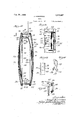
Feb. 23 1926. 1,574,427 I J. KOMOROUS BANK Fil ad June 6. 1924, 2 Sheets-Sheet 1 BANK .2 Sheet 2 I F iled June 6' 924 as covered at its outer surfaces with sheathing material, as, for example, celluloid, represented at 28, the edges of' the sheathing 28 being folded about the flange 26 and interposed between this flange and the flared end-portion 27 of the band.
The cover-section 17 is, in the particular construction illustrated, formed of two sheet- metal disks 29 and 30 shown as con-- nected together by crimping the peripheral edge of the disk 29 about the peripheral edge of the dish 30, as represented at 31, with the inner er ge portion of a celluloid sheet 32 extending over the exterior surfaces of the plate 29 interposed between the criinped portion 31 of the disk 29 and the peri heral edge of the disk 30. The cover 17 is provided on its rear face with offset, outwardlyprojecting, angular lugs 33, preferably stamped from the disk 30 and arranged in a circular series, as represented in Fig. 2,
' faces the cover-section 17 and the body-section 16 are relatively rotatable on each other to cause the lugs 33 to interlock with the flange 19, it being understood from the drawings that this is possible because the bases of the angular lugs 33 lie within a circle of slightly less diameter than the diameter of the opening presented by the inner rdge of the continuous flange 19.
It will be understood from the foregoing that it is necessary, before the cover-section 17 can be removed from the body-section 16 to open the bank. that the cover occupy such a position on the bodysection that the lugs 33 register with the recesses 20, and to prevent the movement of the cover to a position in which the lugs 33 are in such position .of registration, excepting; by one using the proper tool, the following described mechanism is provided.
The disk-like end portion 3 1 of the member 23, shown as crowned, presents at one side of its center the radially-disposed, instruck, portion 35, thereby forming a recess 36 in the surface of the member 2-3 which opposes the disk 25, the flange 24 of the member 23 being also iii-struck in registration with the recess 36, as represented at 37, to cause this flange portion to be of the form shown and present the humpshaped portion 38. The mechanism also comprises the member shown in detail in Fig. and represented at 39, this member, shown as formed from a single sheet of material ber 39 is located in the recess 36 in the member 34, the member 39 fitting itletwise against the bottom wall of these recesses and the free portions 45 and d6 of the arms 10 and 11 extending through the slots 21 in the I flange 19, the member 39 being held in place by means of a tongue 17 cut from the metal of the bottom wall of the recess 56 and bent around, and in overlapping relation to, the cross-piece 4:2. The member 39 is thus located in the space provided between the member 16 and that part of the structure comprising the disk and the ring 18, and by securing themember 39, as stated, its arm portions 40 and 11 are rendered separately deflectible to the right in Fig. 11, for a purpose hereinafter described and when actuated by means of a suitable tool engaging the lugs 43 and 44 which project radially outward beyond the iii-struck portions 37.
The marginal edge of the plate 30, shown as spaced from the plate 29, contains a pair of slots 48 spaced apart a distance equal to the distance between the slots 21 in the flange of the ring 18 and correspondingly converging'the slots 48 being located in such position that when the parts of the bank are assembled to the position shown in Fig. 11 the slots 48 will register with the slots 21 and thus with the extremities of the free portions and 16 of the spring arms which latter, in the normal, locking, position thereof extend through these slots, as represented, and prevent rotation of the cover-section 17 on the body-section 16.
The slot in the bank, through which the coins are introduced therein, is located in the side wall of the bank, and is represented at 49, this slot extending through both the ring 18 and the annular flange 2 1: which latter is preferably provided with the inwardly-extending, substantially parallel. flange portions 50 flanking the opening 49 and formed preferably by slitting the metal of the flange 24 to form partially-swered sections and thereupon turning these sections inwardly to provide the flange portions 50. The slot 49 is provided with a coin-guard represented generally at 51 and shown as constructed from a single. plate 52 8) of spring metal, as, for example. spring brass, this plate being slitted between its edges along the convoluted full line as shown in this figure, to provide the teeth 53 and 54 arranged in staggered and laterallyraises?" Q hrlapp ati h e eet bein h to set them in the positions shown Figs. a 11- The Pla 2 is e e-curved,
, represented in Fig. 10, is held in operative position at the comslot 19, with the teeth 53, a d 5 k carve reins hrs: by inserting it to the position shown in Fig, 11, between the ring 18 the flange 2 1;.
To assemble the cover-section 17 and the. body-sectipnl16, the cover-section is applied to the body-section in such position that its lugs 33 register with the recesses 20,. The operator, while pressing thecover-section and body-section together with sniiicient pressure to overcome the resistance of the spring arms and i6 and permit the marginal cdg portion of the dish 30.. to flatwise contact with the flange 19, rotates the cover section on the bO(l):SQCl3lOI1 to move the extren'iities of the lugs 33 beneath the'flango 19, to a position in which the slots 48 on the cover-section register with the entrenr ities otthespring arms LO and 41, where upon the latter immediately spring outwardly into the slots 48 aiidloclg the coversec tion and body-section against relative rotation, in which position of the parts the as 3 a e hires s he h wit h recesses 29.
Any ui abl hee may b emp oye er withdrawing the extremities of the arms 40 and 11 from the slots 48. Such a tool is r p es t d i is- [1.4, nd hsmp h s a y: portion of angleshape in cr ss-sectipn f which pa d-aphh 'lu s 56 a d .57, of different widths, project, these lugs extending at an angle to the portion 58 of the tool. The ring 18 contains a. pair of toolereceiving slots 59 and 60 located closely adjacentto the lugs 13 and 4A, resp.ectively, thsse slots, which are adapted to receive the lag- portions 56 and 57, respectively, of the tool, being of difierent lengths whereby the tool can be introduced through the ring 18 only when the tool occupies a certain predetermined position. i 7
10 withdraw the locking arms 51,0 and 41 from the openings 41 8, to permit ot the separation of the sections 16 and 17 the ope-r ator inserts the lugs 56 and of the tool through the slots 59 and 60, respectively, to cause them to extend into the space attended by the ring 18, in which position they extend directly opposite, and in overlapped relation to, the lugs {i3 and $4, and then by swinging the tool at its upper end in Fig. 11 to the left in this figure, the tool fulcruming on the nails of the slots 59 and 6,0, withdraws the spring arms 40 and; 41 iron the slots 48.
It will he iinderst hd 26mm he tor going that a bank involving my invention may be comparatively economically constructed, and is strong and durable. FhlgtfllGllllOlfjB, as will be noted, the bank pres ts one c mpering with the locking mechanism by the insertion of objects through the coin-slot 49. "The flanges 50 flanking the coin-slot 19 are Q'E advantage in that they aih'ord obstruction to the bending ot' the teeth 53' and 54. to a set pcsjtion wherein they are snliiciently widely spaced apartto permit the coins to discharge therethrqngh from the bank.
'l h hr nsh ht of e Pa Sh w is h Q -da he ed hs of presen n great rigidity'of structure especiilllyat the pertions where the end p' la te '25 is crimp e d. hpeh he i s le m m h a this'r hs rhh ds t e lat vely r i h s are melt 2h th use f .h hm s a y exp d h hp h i n j t hsse h is he. parts of the strnctnre. I i
The bank. constrncted as shown insnres h ihts q hk hs Qt 1 0 h l ss t an 1 with the cover attlie slots therein, in the erh hhio s th vhr t9 the b d P tion, due to thedivergent, non-radial, arrangement of these slot-s and the similar ara s h t 9 the ex r m t e t aha f jef the legs.
lyhile I have illustrated and described a pe-i iehlhh he t e h y s' my -i v ifi r, do n t h t h n i's ed as l-tamin e li it h t i t sam may he variously modified and altered without departing from the spirit of the invention. V
WVhat I- claim as new, and desire to secure by Le t rsa hht; s
A loanlg strnctnre formed of a hollow eav omp is s s, p ate-membertending crosswise of said ring adjacent one dg her f, and an n -Plat flatv s 9P- h hriha defl ted par es space l zoni aid end-pla te and ring and affording thereith hee -imi ates a t e marg n l d of h heals the hen-h als h vin i win 1 partment, said hollow body contflil ihg an opening throngh which coins deposited in id oin qqmmr i en may b W hdr w heii ih hm, e les r f s i reams an releasable loclcing means for said closnre 1 mean-cl m nt 11 said -strr ierrs t iiahrthi s hcture e hihd o a hQllQW body comprising a ring, a plate-member extending crosswise of said ring adjacent one edge thereof, and an end-plate flatwise opposing said plate-member, said plate-member ha ing a deflected portion spaced from said endplate and ring and afi ording therewith a compartment at the marginal edge of the bank, the bank also having a coin compartment, said hollow body containing an opening through which coins deposited in said coin compartment may be withdrawn therefrom, a closure for said opening, and releasable locking means for said closure comprising a member secured in position at said deflected portion of said plate-member with its free end forming a locking tongue.
A bank structure formed of a hollow body comprising a ring, a plate-member extending crosswise of said ring adjacent one edgethereoit, and an end-plate flatwise opposing said plate-member, said plate-memher having a deflected portion spaced from said end-plate and ring and aliording there with a compartment at the marginal edge of the bank, the bank also having a coin compartment, said hollow body containing an opening through which coins deposited in said coin compartment may be withdrawn therefrom, a closure for said opening, and releasable. locking means for said closure comprising a plate-like member located within said first-referred-to compartment and flatwiseopposing said deflected portion of said plate-member, with its free end forming a locking tongue.
4. A bank structure formed of a hollow body comprising a ring, a cup-shaped mem ber telescoped at its side wall with said ring and an end-plate, portions of the end wall and side wall of said cup-shaped member being spaced from said ring and said end-plate whereby two separate compartments are presented, one for receiving coins and the other for locking means, said hollow body containing an opening through which coins deposited in said coin compartment may be withdrawn, a closure for said opening, and releasable locking means for said closure comprising an element in said second-referred-to compartment.
5. A bank comprising a hollow body port on formed of a ring, a member of general cup-shape with its side wall telescoping within said ring, and a plate extending across the bottom of said member and clampingly engaging said ring, a removable cover i'or the open end of said body portion, .nd means releasably holding said cover in place.
6. A bank comprising a hollow body-portion formed of a ring, a member of general cup-shape with its side wall telescoping within said ring, and a plate extending across the bottom of said member and clampingly engaging said ring, a removable cover for the open end of said body-portion, and means formed of interengaging portions on said cover and ring for releasably holding said cover in place.
7. A bank comprising a hollow body portion for receiving the coins and containing an opening through which the coins may be withdrawn, a closure for said opening, and locking means for securing said closure on said body-portion comprising a spring tongue secured to the body-portion of the bank at its inner end, the extremity otthc outer end portion of said tongue being angularly disposed relative to its inner portion, and a lug on said tongue disposed radially of the center of the bank and extending at an angle to the free extremity of the tongue.
8. A bank structure formed of a hollow body comprising a ring, a cup-shaped member telescoped at its side wall with said ring and an end-plate, portions of the end wall and side wall ofsaid cup-shaped member being spaced from said ring and said end plate whereby two separate compartments are presented, one for receiving coins and the other for locking means, said hollow body containing an opening through which coins deposited in said coin compartment may be withdrawn, a closure for said opening, releasable locking means for said closure comprising a yoke-shaped member fitting flatwise against the outer surface of said deflected portion, the outer extremities of said yoke-member extending angularly relative to the body-portion of said member and beingadapted to interlock with said closure, said yoke member having portions adapted to be separately engaged by a tool introduced into said second-referred-to compartment for withdrawing the ends of said yoke-member from engagement with said cover, said ring being slotted to receive said tool, and means securing said yokemember in position on said cup-shaped member.
9. A bank comprising telescoped members containing a coin-insertion slot through which coins are introduced into the bank, and a coin-guard located at said slot and interposed between the telescoped portions of said members and held in place thereby.
10. A bank comprising members each formed with a continuous sidewall-forming portion at which portions said members are telescoped and with portions extending angularly thereto, said sidewall-forming portions containing registering openings forming a coin-insertion slot through which coins are introduced into the bank, and a coingnard located at said slot and interposed between the side-wall-forming portions of said members and held in place thereby.
11. A bank, comprising telescoped members containing a coin-insertion slot through All] llL)
body comprising a ring, a cup-shaped mem ber, said ring and member being telescoped, a plate flatwise opposing the end wall of said member and secured to said ring, said ring and plate having portions between which said member is interposed, operating -to hold said member in position, and said body containing an opening through which coins deposited in the bank may be withdrawn, a closure for said opening, and releasable locking means for locking said clo sure on said body.
23. A bank, comprising telescoped members containing a coin-insertion slot through which coins are introduced into the bank, and a one-piece coin-guard located at said slot and interposed between the telescoped portion of said members and held in place thereby.
24;. A bank, comprising telescoped members containing a coin-insertion slot through which coins are introduced into the bank, the inner one of said telescoping members being in the form of a cup, an end plate extending across the bottom of said cup and engaging the outer one of said telescoping members, and a coin-guard located at said slot and interposed between the telescoped portions of said members and held in place thereby.
25. A bank, comprising a hollow body portion formed of a ring, and an inner member telescoped with said ring, said ring and memher having registering openings forming a coin slot, a coin-guard at said slot and interposed between said ring and member, a
cover, a locking means for said cover, said member being shaped to form a recess in its outer surface, and one element of said looking means extending into said recess.
26. A bank, comprising a hollow body por= tion formed of a ring, and an inner member telescoped with said ring and formed as a one-piece structure, said ring and member having registering openings forming a coin slot, a coin-guard at said slot and interposed between said ring and member, a cover, and locking means for said cover, said member being shaped to form a recess in its outer surface, and one element of said locking means extending into said recess.
27. A bank formed of a hollow body comprising a ring, and an inner cup-shaped member telescoped at its side wall with said ring, said ring and inner member having registering openings forming a coin slot, a coin-guard at said slot and interposed between said ring and member, a cover, and locking means for said cover, said member being shaped to form a recess in its outer surface, and one element of said locking means extending into said recess.
28. A bank formed of a hollow body comprising a ring, an inner member telescoped with said ring, an end plate rigidly connected with said ring, said ring and inner member having registering openings forming a coin slot, a coin-guard at said slot and interposed between said telescoped members, a cover, and locking means for said cover, said inner member being shaped to form a recess in its outer surface whereby said recessed portion of said inner member and said end plate form a compartment, one element of said locking means extending into said compartment.
29. A bank formed of a hollow body comprising telescoped members and an end plate, said inner telescoped member having an end wall, with portions of said end wall and said inner telescoped member spaced from the outer one of said telescoped members and said end plate, whereby two separate compartments are presented one for receiving coins and the other for locking means, said hollow body containing an opening through which coins deposited in said coin compartment may be withdrawn, a closure for said opening, and releasable locking means for said closure comprising an element inlsaid second-referred-to compartment.
JOSEPH KOMOROUS.
Priority Applications (1)
| Application Number | Priority Date | Filing Date | Title |
|---|---|---|---|
| US718284A US1574427A (en) | 1924-06-06 | 1924-06-06 | Bank |
Applications Claiming Priority (1)
| Application Number | Priority Date | Filing Date | Title |
|---|---|---|---|
| US718284A US1574427A (en) | 1924-06-06 | 1924-06-06 | Bank |
Publications (1)
| Publication Number | Publication Date |
|---|---|
| US1574427A true US1574427A (en) | 1926-02-23 |
Family
ID=24885524
Family Applications (1)
| Application Number | Title | Priority Date | Filing Date |
|---|---|---|---|
| US718284A Expired - Lifetime US1574427A (en) | 1924-06-06 | 1924-06-06 | Bank |
Country Status (1)
| Country | Link |
|---|---|
| US (1) | US1574427A (en) |
-
1924
- 1924-06-06 US US718284A patent/US1574427A/en not_active Expired - Lifetime
Similar Documents
| Publication | Publication Date | Title |
|---|---|---|
| US1896827A (en) | Assortment dispensing container | |
| JPH02130059U (en) | ||
| US1173843A (en) | Ticket-holder. | |
| US1415276A (en) | Card holder | |
| US1574427A (en) | Bank | |
| US3596757A (en) | Money clip | |
| US200962A (en) | Improvement in specie pocket-books | |
| US1778522A (en) | Novelty container | |
| US1560074A (en) | Coin holder | |
| US1464586A (en) | Token holder | |
| US1526273A (en) | Cardcase | |
| US1223946A (en) | Case for currency and other notes. | |
| US1627870A (en) | Dispensing device | |
| US1211248A (en) | Pocket savings-bank. | |
| US1448589A (en) | Can closure | |
| US1330703A (en) | Coin-receptacle | |
| US1198465A (en) | Film-pack. | |
| US1543484A (en) | Coin bank | |
| US1508058A (en) | Key | |
| US1526796A (en) | Receptacle | |
| US1438835A (en) | Necticut | |
| US1633127A (en) | Coin holder | |
| US1470357A (en) | Op cleveland | |
| US1744681A (en) | Loose-powder container | |
| US1438135A (en) | Coin till |