US1521237A - Bag-frame hinge - Google Patents
Bag-frame hinge Download PDFInfo
- Publication number
- US1521237A US1521237A US670406A US67040623A US1521237A US 1521237 A US1521237 A US 1521237A US 670406 A US670406 A US 670406A US 67040623 A US67040623 A US 67040623A US 1521237 A US1521237 A US 1521237A
- Authority
- US
- United States
- Prior art keywords
- frame
- bag
- hinge
- blank
- perforations
- Prior art date
- Legal status (The legal status is an assumption and is not a legal conclusion. Google has not performed a legal analysis and makes no representation as to the accuracy of the status listed.)
- Expired - Lifetime
Links
- 210000003739 neck Anatomy 0.000 description 5
- 238000010276 construction Methods 0.000 description 4
- 230000013011 mating Effects 0.000 description 2
- 230000004048 modification Effects 0.000 description 2
- 238000012986 modification Methods 0.000 description 2
- 238000005452 bending Methods 0.000 description 1
- 230000015572 biosynthetic process Effects 0.000 description 1
- 238000005219 brazing Methods 0.000 description 1
- 238000000926 separation method Methods 0.000 description 1
- 238000005476 soldering Methods 0.000 description 1
Images
Classifications
-
- A—HUMAN NECESSITIES
- A45—HAND OR TRAVELLING ARTICLES
- A45C—PURSES; LUGGAGE; HAND CARRIED BAGS
- A45C13/00—Details; Accessories
- A45C13/04—Frames
Definitions
- This invention relates ⁇ to bag frame hinges as used in pivotally uniting-the two sides:
- Another. purpose is to producehinges that add rather-than detract. from the strength of the frame and which, by reason of their ornamental appezma'nce,-enhance the value of thebag.
- a further aim. is a in the provision of im proved frame hingesithat are-relat vely 1nex-penslve to construct, easy, to apply andoperate and which, due to their structure are prevented from "opening beyond a definite amount.
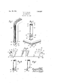
- Fig-ure 2 isa fragm entary side View of the same; 1 showing the hinge elements;
- Figure-4 is ap'lan view-of theframe blank as" shaped ready for bendingydr'awn toan enlarged scale;
- Figure 5 is a View similar to Fig; Q'but showing "an'alternate type of construction.
- Figure 6 is another like View illustrating afur-ther modification ofthe-hingejoint.
- the. invention 'consists in the peculiar and novel shapingl of blanks, including bending, piercing 1 and assembling, toiproduce'a hinge possessing more rigidity and stability than those heretofore made,'-the'reby reducingthe amountofbreakage in the .n' annfacturc of bag frames of this; type and in their subsequent use.
- the upper edges of the necks are tangen tial to the curved extensions and join the blank near slight angular recesses 23 and 24 in the edgeofthe blank,in whatwillbe the outer portion 1% of 'the frame.
- the lugs 27 and 28 are coiled to present sleeves 27' and 28 in register with the perforations and suited to them are hinge pins 32, upset on their inner ends and provided with button heads 33 disposed at the outer sides of the extensions 17, thus constituting a hinge.
- the edges of the recesses 25 and 26 meet and form a positive stop when the bag frame is opened as shown in F igj 3 thus avoiding binding of the hinge joints when opening the bag.
- the blank is used like that described except that the lug 27 is made wider, occupying the space'of the recess 29 and the lug 28, on the opposite end of the blank is wholly omitted, thus permitting coiling the lug, as at 35, about the body of the pin 32, which passes through the extensions 17 and 18 in the manner already described.
- Figure 6 discloses a further variation in construction, in which both lugs 27 and 28 are omitted, the hinge being made of the elements 17 and 18 held pivotally together with tubular or like rivets 36, the blanks being cut at an angle on their inner members 13, in conformity with the angle of the outer members 14:.
- overlying neck elements 19 and 20 tend to stiffen and re-enforce the ends of the frame members very materially and are held rigidly in place by brazing or soldering so that no crevice exists and separation cannot occur.
- a combined bag frame and binge comprising a pair of duplicate channelled side frames. arranged in reverse end relation, curved projections oneach of the ends of said frames, said projections being perforate and bent to closely'overlie the outer surfaces of the channelled frames, the perforations in said projection being in register one with another ateach end of the frame and with the other surfaceof the channelled frames,
- a bag frame hinge comprising in combination with the frame sides, hinge elements von the ends of each side frame disposed in a plane at right angles to the plane o-f the side frames, other hinge elements disposed in planes parallel to the side frames, and pins passing through adjacent hinge elements at each end of the frame sides upon which said sides pivot.
- a bag frame hinge comprising in combination with a pair of frame sides composed of like members arranged in opposed relation, re-enforcements formed by extensions on the ends of said members folded at an angle of approximately forty-five degrees closely thereover, said extensions containing central perforations, and rivets in the mentioned perforations forming pivots on which said frame sides turn.
- a bag frame hinge comprising in combination with a pair of frame sides composed of like membersarranged in opposed relation, re-enforcements formed by extensions on the ends of said members folded at an angle of forty-five degrees closely thereover, said extensions containing central perforations, rectangular projections on at least one end of each side frame coiled to produce a sleeve, and pins passing through the mentioned perforations into adjacenti sleeves,
- said pins constituting the pivotal axes for the bag frame.
Landscapes
- Toys (AREA)
Description
E. A. FULLER BAG FRAME HINGE Filed Oct. 24, 1923 ATTORNEY Patented Dec. 30, 1924'.
run-"r;
FRANZA. runnnngorfn'nwanx. new a'n asny, *Assr'euoa Te ms Jkn: MERGOTI com PAN-Y; or NEWARK, new mess A coa-eonnrzcw on DELAWARE.
BAG-FRHME HINGE- Appliaatioufiied October 24 1923; Serial No. 670,496;
To a ZZ whOm 'it-may concern:
Be it known that I, FRANZ A. FU LER, acitizenof the United States, a resident of Newark, inthe county of Essexand State of New Jersey, have invented certain new and useful Improvements in BagFra-me Hinges,-of whichthe following-is a specification; p
This invention relates} to bag frame hinges as used in pivotally uniting-the two sides:
of a-conventionalbagframe structure and:
has as its primary object to provide unusually strong and efiective hinges,- all elements ofiwhich i'except the pins, are integral with the blanks from which the frame is made.-' V
Another. purpose is to producehinges that add rather-than detract. from the strength of the frame and which, by reason of their ornamental appezma'nce,-enhance the value of thebag.
A further aim. is a in the provision of im proved frame hingesithat are-relat vely 1nex-penslve to construct, easy, to apply andoperate and which, due to their structure are prevented from "opening beyond a definite amount. v
These several important-aims and'objects, togetherwith others which'will become ap-' parentfurther on, are accomplished bythe novel construction and: arran gementi of parts hereinafter described and? shown in the accompanyingdrawing; forming a material part. ofthis disclosure and in which Figure I is a fragmentary perspective View showing a part of a bag frame with a preferred embodiment of tlIG-lIlTQlltiOIl incorporated therewith.
.Fig-ure 2 isa fragm entary side View of the same; 1 showing the hinge elements;
Figure-Sis an endview of the-same, the
' hinge-being in an extreme openpositiom Figure-4 is ap'lan view-of theframe blank as" shaped ready for bendingydr'awn toan enlarged scale;
Figure 5 is a View similar to Fig; Q'but showing "an'alternate type of construction.
[Figure 6 is another like View illustrating afur-ther modification ofthe-hingejoint.
Stated in general terms the. invention 'consists in the peculiar and novel shapingl of blanks, including bending, piercing 1 and assembling, toiproduce'a hinge possessing more rigidity and stability than those heretofore made,'-the'reby reducingthe amountofbreakage in the .n' annfacturc of bag frames of this; type and in their subsequent use. p
Referring now more in detail to the drawing, the numeral lOdesi-gnates one'offthc theseelementsbeing further bent at. a right angle in the plane of their width to extend down the sides as usuah again referring toy the blank in Fig. 4:, it. will benoticed that the ends 15 and 1-6 are not alike both present extensions 17 and 18 respectively, curved except for 'the necks 19and 20 connecting. witlrthe main or body portion of the blank and containing central openings and22.
The upper edges of the necks are tangen tial to the curved extensions and join the blank near slight angular recesses 23 and 24 in the edgeofthe blank,in whatwillbe the outer portion 1% of 'the frame.
Therecess below the neck 19 is bounded at its opposite side by a parallellug 27 extending from the end. 15 of the blank and at its opposite edge" is a rectangular corner recess 29.
At the end 16 of theblank a recess-"26 reaches below theneck 20, itsoppositeedge bein bounded by. an o utstand-ing lug. 28.
If a duplicate blank should beJreversed" so that its end 15 would engage the end. 1t?
of the blank shown in Fig. 4, it would be found that its lug 27 would enter the space 26, clearing the extension 18 and that the lug 28 would fit the recess 29.
It will be seen that the necks are bent,
after the blanks have been given a channel formation, at an approximate angle of fortyiive degrees, as indicated by the folding lines 30 and 31, from the notches, tightly over the curved surfaces 14- at the ends of the blanks, and the extensions 17 and 18 bent to present their perforations in register with those of the mating frame member, as illustrated in Fig. l, the center of the openings 21 and 22 being disposed substantially in the plane of the flat elements 13 of the frame.
The lugs 27 and 28 are coiled to present sleeves 27' and 28 in register with the perforations and suited to them are hinge pins 32, upset on their inner ends and provided with button heads 33 disposed at the outer sides of the extensions 17, thus constituting a hinge. v
The edges of the recesses 25 and 26 meet and form a positive stop when the bag frame is opened as shown in F igj 3 thus avoiding binding of the hinge joints when opening the bag.
In the modification shown in Fig. 5 a
blank is used like that described except that the lug 27 is made wider, occupying the space'of the recess 29 and the lug 28, on the opposite end of the blank is wholly omitted, thus permitting coiling the lug, as at 35, about the body of the pin 32, which passes through the extensions 17 and 18 in the manner already described.
Figure 6 discloses a further variation in construction, in which both lugs 27 and 28 are omitted, the hinge being made of the elements 17 and 18 held pivotally together with tubular or like rivets 36, the blanks being cut at an angle on their inner members 13, in conformity with the angle of the outer members 14:.
The overlying neck elements 19 and 20 tend to stiffen and re-enforce the ends of the frame members very materially and are held rigidly in place by brazing or soldering so that no crevice exists and separation cannot occur.
Experience has demonstrated that the or ganization above described is highly efficient and while I have presented approved embodiments of my invention, I do not care tovrestrict myself to theeXact details of construction herein set forth, it being obvious that minor variations, thereof, not involving the exercise of invention, maybe made by any skilled mechanic, and'such departures from what is herein described and claimed, I consider within the scope and terms of my claims.v
Having thus described my invention, what I claim as new and desire to secure by Letters Patent, is I 1. A combined bag frame and binge comprising a pair of duplicate channelled side frames. arranged in reverse end relation, curved projections oneach of the ends of said frames, said projections being perforate and bent to closely'overlie the outer surfaces of the channelled frames, the perforations in said projection being in register one with another ateach end of the frame and with the other surfaceof the channelled frames,
and pivots secured in the perforations on 3. A combined bag frame and hinge com prising apair of ,duplicate channelled side frames arranged in reverse end relation,
curved projections on each'of the ends'of said frames, said projections being perforate and bent at an angle to fold closely over the outer surfaces of the channel and protrude at right angles to bring the perforations in adjacent projections into registration, pivots passing through the perforations on which said side frames are hingedly engaged,-and lugs extending'in staggered relation from the ends of said frames coiled to produce mating sleeves through which said pivots pass. V
4. A bag frame hinge comprising in combination with the frame sides, hinge elements von the ends of each side frame disposed in a plane at right angles to the plane o-f the side frames, other hinge elements disposed in planes parallel to the side frames, and pins passing through adjacent hinge elements at each end of the frame sides upon which said sides pivot. i I
5. A bag frame hinge comprising in combination with a pair of frame sides composed of like members arranged in opposed relation, re-enforcements formed by extensions on the ends of said members folded at an angle of approximately forty-five degrees closely thereover, said extensions containing central perforations, and rivets in the mentioned perforations forming pivots on which said frame sides turn. I I
6. A bag frame hinge comprising in combination with a pair of frame sides composed of like membersarranged in opposed relation, re-enforcements formed by extensions on the ends of said members folded at an angle of forty-five degrees closely thereover, said extensions containing central perforations, rectangular projections on at least one end of each side frame coiled to produce a sleeve, and pins passing through the mentioned perforations into adjacenti sleeves,
said pins constituting the pivotal axes for the bag frame.
This specification signed and witnessed this 22nd day of October, 1923.
FRANZ A. FULLER.
- Witnesses:
M. KLEEMAN,
PAUL E. HARTMAN.
Priority Applications (1)
| Application Number | Priority Date | Filing Date | Title |
|---|---|---|---|
| US670406A US1521237A (en) | 1923-10-24 | 1923-10-24 | Bag-frame hinge |
Applications Claiming Priority (1)
| Application Number | Priority Date | Filing Date | Title |
|---|---|---|---|
| US670406A US1521237A (en) | 1923-10-24 | 1923-10-24 | Bag-frame hinge |
Publications (1)
| Publication Number | Publication Date |
|---|---|
| US1521237A true US1521237A (en) | 1924-12-30 |
Family
ID=24690277
Family Applications (1)
| Application Number | Title | Priority Date | Filing Date |
|---|---|---|---|
| US670406A Expired - Lifetime US1521237A (en) | 1923-10-24 | 1923-10-24 | Bag-frame hinge |
Country Status (1)
| Country | Link |
|---|---|
| US (1) | US1521237A (en) |
Cited By (4)
| Publication number | Priority date | Publication date | Assignee | Title |
|---|---|---|---|---|
| US2578612A (en) * | 1946-07-26 | 1951-12-11 | Stregack Boris Martin | Invisibly hinged handbag frame |
| US2751956A (en) * | 1954-04-21 | 1956-06-26 | Edward M Karron | Method of making bag frames and blanks therefor |
| US20130161944A1 (en) * | 2011-06-29 | 2013-06-27 | Lance D. Bailey | Downspout hinge systems and methods |
| US20130161943A1 (en) * | 2011-06-29 | 2013-06-27 | Lance D. Bailey | Sandwich coupling mechanism |
-
1923
- 1923-10-24 US US670406A patent/US1521237A/en not_active Expired - Lifetime
Cited By (6)
| Publication number | Priority date | Publication date | Assignee | Title |
|---|---|---|---|---|
| US2578612A (en) * | 1946-07-26 | 1951-12-11 | Stregack Boris Martin | Invisibly hinged handbag frame |
| US2751956A (en) * | 1954-04-21 | 1956-06-26 | Edward M Karron | Method of making bag frames and blanks therefor |
| US20130161944A1 (en) * | 2011-06-29 | 2013-06-27 | Lance D. Bailey | Downspout hinge systems and methods |
| US20130161943A1 (en) * | 2011-06-29 | 2013-06-27 | Lance D. Bailey | Sandwich coupling mechanism |
| US8935830B2 (en) * | 2011-06-29 | 2015-01-20 | Lance D. Bailey | Downspout hinge systems and methods |
| US8938858B2 (en) * | 2011-06-29 | 2015-01-27 | Lance D. Bailey | Sandwich coupling mechanism |
Similar Documents
| Publication | Publication Date | Title |
|---|---|---|
| US2074843A (en) | Bag frame | |
| US734092A (en) | Game and game-board. | |
| US1521237A (en) | Bag-frame hinge | |
| US2097927A (en) | Method of making bag frames and blanks therefor | |
| US1361378A (en) | Bag-fastener | |
| US564593A (en) | Paper box | |
| US1501713A (en) | Folding rule | |
| US1690046A (en) | Receptacle | |
| US1505593A (en) | Folding hinge | |
| GB467854A (en) | Improvements in or relating to advertising circulars, showcards or the like | |
| US955314A (en) | Folding rule. | |
| US1337507A (en) | Paper box | |
| US1758955A (en) | Window screen | |
| US974643A (en) | Folding umbrella. | |
| US1810508A (en) | Hinge | |
| US1787710A (en) | Folding closure for tobacco pouches | |
| US1409663A (en) | Hinge | |
| US1501134A (en) | Suit box | |
| US1839788A (en) | Foldable extension device | |
| US1473932A (en) | Method of constructing hand bags | |
| US2151467A (en) | Paperhanger's folding straightedge | |
| US649705A (en) | Curtain for cabinets, desks, & c. | |
| US1737494A (en) | Ironing-board hinge | |
| US1138814A (en) | Folding crate or box. | |
| US351745A (en) | Extension-valise |