US1471069A - Jar or bottle clamp - Google Patents
Jar or bottle clamp Download PDFInfo
- Publication number
- US1471069A US1471069A US549183A US54918322A US1471069A US 1471069 A US1471069 A US 1471069A US 549183 A US549183 A US 549183A US 54918322 A US54918322 A US 54918322A US 1471069 A US1471069 A US 1471069A
- Authority
- US
- United States
- Prior art keywords
- jar
- bottle clamp
- base
- sections
- brackets
- Prior art date
- Legal status (The legal status is an assumption and is not a legal conclusion. Google has not performed a legal analysis and makes no representation as to the accuracy of the status listed.)
- Expired - Lifetime
Links
- 241000876852 Scorias Species 0.000 description 1
- 230000004308 accommodation Effects 0.000 description 1
- 238000010438 heat treatment Methods 0.000 description 1
- 239000002184 metal Substances 0.000 description 1
- 239000004576 sand Substances 0.000 description 1
- MEYZYGMYMLNUHJ-UHFFFAOYSA-N tunicamycin Natural products CC(C)CCCCCCCCCC=CC(=O)NC1C(O)C(O)C(CC(O)C2OC(C(O)C2O)N3C=CC(=O)NC3=O)OC1OC4OC(CO)C(O)C(O)C4NC(=O)C MEYZYGMYMLNUHJ-UHFFFAOYSA-N 0.000 description 1
Images


Classifications
-
- B—PERFORMING OPERATIONS; TRANSPORTING
- B67—OPENING, CLOSING OR CLEANING BOTTLES, JARS OR SIMILAR CONTAINERS; LIQUID HANDLING
- B67B—APPLYING CLOSURE MEMBERS TO BOTTLES JARS, OR SIMILAR CONTAINERS; OPENING CLOSED CONTAINERS
- B67B7/00—Hand- or power-operated devices for opening closed containers
- B67B7/18—Hand- or power-operated devices for opening closed containers for removing threaded caps
Definitions
- This invention relates, to jar Vises; or.
- Figure 1 is a view perspective.
- Figure 2 1s a side elevation, show ng the devlcefin Operative relation with a ar in F'gure 3 is a plan view of -the'sectiona-l base carrying the gripping elements.
- Figures 4, Sand 6 are detail viewsin perspective.
- '1 represents the base composed of two sectionsl and l v which are slidably o'r ad 210. justably connected by meansof bars '2 rigid as at 3, and slidably .en-
- gaging 1 as at 1. g 7 I Section 1 and section l s each provided,-
- each of said sections is also provided with a plurality of openings 7 p for the accommodation of thegripping "or holding posts 8, and for convenience each 40 pair of these grippingposts maybe tiedtogether by the metal band 9.
- f Holding hooks 1b maybe mountedf upon one of thecross-bars l5, and adapted to swing into'engagement with the opposite purpose, of holdingthe i device in operative relation; v As's'uggested above, the base; is provided cross-bar forgthe with a" plurality of openings 7* to receive jar to beoperated upon.
- a base composed of'two sections slidably connected, holding elements in said; base, operatinglevers pivoted to each other inter- 'mediate their ends and swinginglysecured' upon the opposite sections of saidbase.
Landscapes
- Engineering & Computer Science (AREA)
- Mechanical Engineering (AREA)
- Orthopedics, Nursing, And Contraception (AREA)
Description
J. SCIORTINO JAR OR BOTTLE CLAMP Filed Apr'agl 5, 1922 3 Sheets-Sheet 1 sad tunic:
fo$eph Scoria'na 6 Ho: mu;
Oct. 161", 1923. 1,471,069
J. SCIORTINO H Filed April 5, 1922 3 Sheets-Sheet 2 Oct. 16, 1923. 1,471,069 J. scloR'nNo JAR 0R BOTTLE CLAMP Filed April 5. 1922 a Sheets-Sheet 5 20 position to be operated upon.
f i ly attached to 1,
Patented @ct. 16,1923.
JOSEPH soxonrrno; or YOUNGSTOWN, 0310.
JAR on BorrtnoLAMP.
Application filed April 3,
3 ToaZZ whom it may concern:
Be it known that I, JosnPIrScIoR'rINo, States, residing at' Youngstown, in the countygofldahoning E'and State of Ohio,a-have invented certain citizenof the United new and usefullmprovements in Jar or Bottle Clamps, of Which the followingi's a specification.
This invention relates, to jar Vises; or.
1 holders,the object being to provide a' convenient and effective device'for firmly holding the Jar while turning the cap on or oil, as well as for heating'the ar and ts contents if desired, and without dangerof 1 breaking the jar. V I
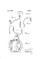
Inthe drawing, Figure 1 is a view perspective. u
Figure 2 1s a side elevation, show ng the devlcefin Operative relation with a ar in F'gure 3 is a plan view of -the'sectiona-l base carrying the gripping elements. Figures 4, Sand 6 are detail viewsin perspective. V
The same reference characters designate corresponding parts of the device through out the various figures ofthe drawings; '1 represents the base composed of two sectionsl and l v which are slidably o'r ad 210. justably connected by meansof bars '2 rigid as at 3, and slidably .en-
gaging 1 as at 1. g 7 I Section 1 and section l s each provided,-
adjacent its inner edge, with uprights-'5; each carrying at itsupp'er end the forked bracketffil .Each of said sections is also provided with a plurality of openings 7 p for the accommodation of thegripping "or holding posts 8, and for convenience each 40 pair of these grippingposts maybe tiedtogether by the metal band 9. i
10 represents clamping arms pivotally connected, as at 11, the innerends of which are swingingly secured in the forked brackets 6, by means of rivets or bolts 12, while the outer ends are provided with tubular extensions 13. Slidably engaging the tubular extensions 13 are the rods 14 which are tied together at theirouter ends bythe '50 cross-bars 15, thus formingwhat may be termed clamping handles for the opera tion of the device, and becauseof theirslid- 'ter,
i922.v een ino. 549,1 3.:
height'of the jar' in order that the upper in'giengagement with the tubes 13, may be drawn outwardly. to conform. to J the I gripping e1ements'1 15 may embrace the 'jar at its upper end rather than near thecem V thus-avoiding dangerof breaking the jar. f Holding hooks 1b maybe mountedf upon one of thecross-bars l5, and adapted to swing into'engagement with the opposite purpose, of holdingthe i device in operative relation; v As's'uggested above, the base; is provided cross-bar forgthe with a" plurality of openings 7* to receive jar to beoperated upon.
In operation" the'jar 'isplaced upon the f i 770 the two sections 1 and 1 are separated by base inside of the grlppingpostss, while 5, the gripping posts- 8, in order that the. postsvm'ay be'adjusted to the size ofthe forcing orpulling the operating handlesf for operation.
.I 'claiinc' Y 1. In an article of thecharacter described,
a base composed of'two sections slidably connected, holding elements in said; base, operatinglevers pivoted to each other inter- 'mediate their ends and swinginglysecured' upon the opposite sections of saidbase. 2. In an article of the character described,
' a base composed of two-sections slidably connected, each section being provided, ad-
jacent its inner face, with a pair of op.-
positely disposed forked brackets, holding elements in said base, operating-levers swivelly connected with each other intermediate their ends and swingingly secured in said brackets. v
f 3.; In anarticle of thecharacterdescribed, a base composed of two sections slidably 'connected, each of saidsectionsbeingpm vided,,adjacent its inner edge, with apairj p of oppositely disposed brackets, holding elements in saidbase, operating levers swivelw 1y connected intermediate their ends and In testimony whereof I have hereunto havl n then lnner ends swmglngly secured affixed my slgnature 1n the presence 01? two 1n Sal Brackets, each of szud levers belng ,wltnesses.
provided at its outer end with a tubular JOSEPH SCIORTINO. 5 extensign, a pair of standzufds slidahly en WVitnesses: i
gaging W i bl er'e sii n and t ed w e ls w -m w V gether with a cross-bar. 7 j JOHN G Gommr.
Priority Applications (1)
| Application Number | Priority Date | Filing Date | Title |
|---|---|---|---|
| US549183A US1471069A (en) | 1922-04-03 | 1922-04-03 | Jar or bottle clamp |
Applications Claiming Priority (1)
| Application Number | Priority Date | Filing Date | Title |
|---|---|---|---|
| US549183A US1471069A (en) | 1922-04-03 | 1922-04-03 | Jar or bottle clamp |
Publications (1)
| Publication Number | Publication Date |
|---|---|
| US1471069A true US1471069A (en) | 1923-10-16 |
Family
ID=24191979
Family Applications (1)
| Application Number | Title | Priority Date | Filing Date |
|---|---|---|---|
| US549183A Expired - Lifetime US1471069A (en) | 1922-04-03 | 1922-04-03 | Jar or bottle clamp |
Country Status (1)
| Country | Link |
|---|---|
| US (1) | US1471069A (en) |
-
1922
- 1922-04-03 US US549183A patent/US1471069A/en not_active Expired - Lifetime
Similar Documents
| Publication | Publication Date | Title |
|---|---|---|
| US1471069A (en) | Jar or bottle clamp | |
| FR2486553A1 (en) | APPARATUS FOR CHECKING AND IRONING KNITTED ARTICLES SUCH AS TIGHTS. | |
| US1240852A (en) | Bag-holder. | |
| US1074974A (en) | Post-puller. | |
| US1609776A (en) | Stand and tilter for barrels and the like | |
| US2500047A (en) | Adjustable clamp truck | |
| US680263A (en) | Lid or plate lifter. | |
| US993422A (en) | Apparatus for stripping waste off single-headed tubes, bobbins, or pirns. | |
| US1185627A (en) | Pipe-lifting device. | |
| US1770343A (en) | Grab | |
| US788738A (en) | Oil-well tube-clamp. | |
| US725923A (en) | Lifting device. | |
| US2045272A (en) | Icing mechanism | |
| US1420273A (en) | Jar lifter | |
| US765851A (en) | Laundry-tongs. | |
| EP3056435A3 (en) | Device for holding and releasing a remotely operated vehicle | |
| US1087649A (en) | Store-goods lifter. | |
| US805178A (en) | Machine for treating pineapples. | |
| US638325A (en) | Fruit-evaporator. | |
| US868431A (en) | Stump-puller. | |
| US1210853A (en) | Vegetable-washing machine. | |
| US1252108A (en) | Can holding and opening device. | |
| US791367A (en) | Barrel receiving and handling apparatus. | |
| US870039A (en) | Tire-bench. | |
| US1168168A (en) | Butter-mold. |