US1379110A - Safety-catch - Google Patents
Safety-catch Download PDFInfo
- Publication number
- US1379110A US1379110A US308241A US30824119A US1379110A US 1379110 A US1379110 A US 1379110A US 308241 A US308241 A US 308241A US 30824119 A US30824119 A US 30824119A US 1379110 A US1379110 A US 1379110A
- Authority
- US
- United States
- Prior art keywords
- hook
- pin
- catch
- safety
- brooch
- Prior art date
- Legal status (The legal status is an assumption and is not a legal conclusion. Google has not performed a legal analysis and makes no representation as to the accuracy of the status listed.)
- Expired - Lifetime
Links
- 238000010276 construction Methods 0.000 description 6
- 238000000034 method Methods 0.000 description 2
- 241001446467 Mama Species 0.000 description 1
- 210000004905 finger nail Anatomy 0.000 description 1
- 239000002184 metal Substances 0.000 description 1
- 210000003813 thumb Anatomy 0.000 description 1
Images
Classifications
-
- A—HUMAN NECESSITIES
- A44—HABERDASHERY; JEWELLERY
- A44B—BUTTONS, PINS, BUCKLES, SLIDE FASTENERS, OR THE LIKE
- A44B9/00—Hat, scarf, or safety pins or the like
- A44B9/12—Safety-pins
- A44B9/18—Hinges; Locking devices
-
- Y—GENERAL TAGGING OF NEW TECHNOLOGICAL DEVELOPMENTS; GENERAL TAGGING OF CROSS-SECTIONAL TECHNOLOGIES SPANNING OVER SEVERAL SECTIONS OF THE IPC; TECHNICAL SUBJECTS COVERED BY FORMER USPC CROSS-REFERENCE ART COLLECTIONS [XRACs] AND DIGESTS
- Y10—TECHNICAL SUBJECTS COVERED BY FORMER USPC
- Y10T—TECHNICAL SUBJECTS COVERED BY FORMER US CLASSIFICATION
- Y10T24/00—Buckles, buttons, clasps, etc.
- Y10T24/46—Pin or separate essential cooperating device therefor
- Y10T24/4604—Pin or separate essential cooperating device therefor having distinct guiding, holding, or protecting means for penetrated portion
- Y10T24/4634—Pin or separate essential cooperating device therefor having distinct guiding, holding, or protecting means for penetrated portion including relatively movable guiding, holding, or protecting components or surfaces
- Y10T24/4643—Pin or separate essential cooperating device therefor having distinct guiding, holding, or protecting means for penetrated portion including relatively movable guiding, holding, or protecting components or surfaces with slidable connection between nonself-biasing components
Definitions
- My object is to make a safety catch for brooches and the like, and my invention consists of the novel features herein shown, described and claimed.
- Specifically my object is to provide .a safety pin construction for brooches and the like which cannot be accidentally or easily unhooked.
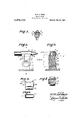
- Figure 1 is a perspective from the rear side of a brooch provided with a safety pin construction having a catch embodyingthe principles of my invention.
- Fig. 2 is a greatly enlarged fragmentary side elevation showing the pin and hook and safety catch. the view being taken looking in the direction indicated by the arrow 2 in Fig. 3.
- Fig. 3 is a cross sectional detail on the line 3-3 of Fig. 2.
- Fig. 4 is a longitudinal sectional detail .on the lines 1& of Figs. 2 and'3 and looking downwardly as indicated by the arrows.
- Fig. 5 is a side elevation of the catch member removed from the mounting and illustrating the process of construction.
- Fig. 6 is a top plan View of the parts shown in Fig. 5.
- the brooch frame 1 has a bearing bracket 2 extending from one side and the pin 3 is hinged to the bearing bracket.
- the hook bracket 4 is. rigidly fixed at the opposite side of thebrooch frame 1 from thebearing bracket 2 and has a hook 5 to receive the end of the pin 3 as in a safety pin construction.
- the object of my invention is to provide a safety catch 6 to hold the point of the pin 3 lockedin the hook so that the brooch cannot become disconnected from the garment accidentally or easily removed intentionally.
- Figs. 2, 3 and 41 have shownthe safety catch construction greatly enlarged relative to the normal size and the details are as follows:
- the hook bracket 4' is a post of consider- Specification of Letters Patent.
- the safety catch mem ber is slidingly mounted in the opening portions 7 and 8, and the safety catch member comprises the lower circular portion 9 and the upper tongue-shaped portion 10 fitting tightly in the portions 7 and 8 of the opening.
- a lug 11 projects upwardly from the outer end of the portion 10 to form a stop and hold the catch member from sliding through the opening.
- a concavity 12 is formed in the upper face of the portion 10, thus producing an edge 13 which is normally in opposition to the point 14: of the hook.
- the catch member 15v thus constructed is moved to the left in Fig. 3, as shown in dotted lines, then the pin 3 is placed in the hook 5 and the catch member 15 is moved to the right thus pressing the edge 13 under the pin 3 and straining the hook 5 until the edge 13 snaps past the pin and rests in the concavity 12.
- the catch member 15 is upset after being placed in the opening to form a stop 16 to prevent the catch member from being withdrawn from the opening.
- the brooch or the like is applied to the garment with the pin 3 hooked through the garment and placed in the hook 5; then sufiicient force is applied to the catch member 15 to snap the catch member into place, as shown in full lines in Fig. 3, and the tension of the hook 5 will hold the pin 3 in the concavity 12 and the safety pin construction cannot be unhooked except by pressing against the catch member 15 with the .thumb or finger nail hard enough to snap it pastthe pin 3, so that the brooch or the like cannot accidentally be unhooked and can only be intentionally unhookedwith care and ingenuity.
- Figs. 5 and 6 I have illustrated the process of constructing the catch member 15.
- the lower circular portion 9 is preferably cut from a piece of round rod, and
- the upper extension portion 8 is cut from a bar of soft metal and soldered or welded to the portion 9.] r
- the bar has a portion 8, shown in dotted lines, which is knocked up to produce the lug 11, and at the other end the bar 8 has a portion 8", shown in dotted lines, and this portion 8 is knocked around sidewise to produce the stop 16.
- latch member mounted to slide bodily.
- a safety catch for brooch pins and the like a base, a spring hook mounted upon the base adapted to spring outwardly therefrom, a latch member slidably mounted upon the base and in a slot in the hook, means for retaining the latch member from being moved out of the slot in the hook, a lip upon an upper edge of the latch member positioned to operate under the hook, a concavity in the top of the latch member back of the lip, the lip being disposed at such a height relative to the hook that in passing under a pin member seated in the hook it will spring the hook upwardly and snap past the pin'member whereby the pin member will become seated in the concavity behind the lip.
Landscapes
- Hooks, Suction Cups, And Attachment By Adhesive Means (AREA)
Description
M. H. LE man. sum cuca." APPLICATION FILED JULYZ; I919 I mama May 24,1921.
I NVEN TOR.
PATENT OFFICE.
MOAD H. LE MARR, F LOS ANGELES, CALIFORNIA.
SAFETY-CATCH.
Application filed July 2, 1919.
To all whom it may concern:
Be it knownthat I, MOAD H. LE MARK, a
' citizen of the United States, residing t Los Angeles, in the county of Los Angeles and State of California, have invented new and useful Improvements in Safety-Catches, of which the following is a specification.
My object is to make a safety catch for brooches and the like, and my invention consists of the novel features herein shown, described and claimed.
Specifically my object is to provide .a safety pin construction for brooches and the like which cannot be accidentally or easily unhooked.
Figure 1 is a perspective from the rear side of a brooch provided with a safety pin construction having a catch embodyingthe principles of my invention.
Fig. 2 is a greatly enlarged fragmentary side elevation showing the pin and hook and safety catch. the view being taken looking in the direction indicated by the arrow 2 in Fig. 3.
Fig. 3 is a cross sectional detail on the line 3-3 of Fig. 2.
Fig. 4 is a longitudinal sectional detail .on the lines 1& of Figs. 2 and'3 and looking downwardly as indicated by the arrows. Fig. 5 is a side elevation of the catch member removed from the mounting and illustrating the process of construction.
Fig. 6 is a top plan View of the parts shown in Fig. 5.
The brooch frame 1 has a bearing bracket 2 extending from one side and the pin 3 is hinged to the bearing bracket. The hook bracket 4: is. rigidly fixed at the opposite side of thebrooch frame 1 from thebearing bracket 2 and has a hook 5 to receive the end of the pin 3 as in a safety pin construction. The object of my invention is to provide a safety catch 6 to hold the point of the pin 3 lockedin the hook so that the brooch cannot become disconnected from the garment accidentally or easily removed intentionally. In Figs. 2, 3 and 41 have shownthe safety catch construction greatly enlarged relative to the normal size and the details are as follows:
The hook bracket 4'is a post of consider- Specification of Letters Patent.
Patented May 24, 1921.
Serial No. 308,241.
A lug 11 projects upwardly from the outer end of the portion 10 to form a stop and hold the catch member from sliding through the opening. A concavity 12 is formed in the upper face of the portion 10, thus producing an edge 13 which is normally in opposition to the point 14: of the hook The catch member 15v thus constructed is moved to the left in Fig. 3, as shown in dotted lines, then the pin 3 is placed in the hook 5 and the catch member 15 is moved to the right thus pressing the edge 13 under the pin 3 and straining the hook 5 until the edge 13 snaps past the pin and rests in the concavity 12. The catch member 15 is upset after being placed in the opening to form a stop 16 to prevent the catch member from being withdrawn from the opening.
In actual practice the brooch or the like is applied to the garment with the pin 3 hooked through the garment and placed in the hook 5; then sufiicient force is applied to the catch member 15 to snap the catch member into place, as shown in full lines in Fig. 3, and the tension of the hook 5 will hold the pin 3 in the concavity 12 and the safety pin construction cannot be unhooked except by pressing against the catch member 15 with the .thumb or finger nail hard enough to snap it pastthe pin 3, so that the brooch or the like cannot accidentally be unhooked and can only be intentionally unhookedwith care and ingenuity.
In Figs. 5 and 6 I have illustrated the process of constructing the catch member 15. The lower circular portion 9 is preferably cut from a piece of round rod, and
the upper extension portion 8 is cut from a bar of soft metal and soldered or welded to the portion 9.] r
. The bar has a portion 8, shown in dotted lines, which is knocked up to produce the lug 11, and at the other end the bar 8 has a portion 8", shown in dotted lines, and this portion 8 is knocked around sidewise to produce the stop 16. v
Various changes may be made without departing from the spirit of my invention as claimed.
latch member mounted to slide bodily.
through the post below the hook and having a lip adapted to ride past a pin member received within said hook whereby the pin member is held within the hook.
In a safety catch for brooch pins and the like a base, a spring hook mounted upon the base adapted to spring outwardly therefrom, a latch member slidably mounted upon the base and in a slot in the hook, means for retaining the latch member from being moved out of the slot in the hook, a lip upon an upper edge of the latch member positioned to operate under the hook, a concavity in the top of the latch member back of the lip, the lip being disposed at such a height relative to the hook that in passing under a pin member seated in the hook it will spring the hook upwardly and snap past the pin'member whereby the pin member will become seated in the concavity behind the lip.
In testimony whereof I have signed my name to this specification.
MOAD H. LE MARR.
Priority Applications (1)
| Application Number | Priority Date | Filing Date | Title |
|---|---|---|---|
| US308241A US1379110A (en) | 1919-07-02 | 1919-07-02 | Safety-catch |
Applications Claiming Priority (1)
| Application Number | Priority Date | Filing Date | Title |
|---|---|---|---|
| US308241A US1379110A (en) | 1919-07-02 | 1919-07-02 | Safety-catch |
Publications (1)
| Publication Number | Publication Date |
|---|---|
| US1379110A true US1379110A (en) | 1921-05-24 |
Family
ID=23193157
Family Applications (1)
| Application Number | Title | Priority Date | Filing Date |
|---|---|---|---|
| US308241A Expired - Lifetime US1379110A (en) | 1919-07-02 | 1919-07-02 | Safety-catch |
Country Status (1)
| Country | Link |
|---|---|
| US (1) | US1379110A (en) |
-
1919
- 1919-07-02 US US308241A patent/US1379110A/en not_active Expired - Lifetime
Similar Documents
| Publication | Publication Date | Title |
|---|---|---|
| US1379110A (en) | Safety-catch | |
| US857105A (en) | Attachment for holding ear ornaments. | |
| US1380459A (en) | Tie-clasp | |
| US1707591A (en) | Necktie holder | |
| US424569A (en) | Halp to john c | |
| US1019578A (en) | Safety-pin. | |
| US1074270A (en) | Pin. | |
| US914150A (en) | Safety-catch for stick-pins and similar articles of jewelry. | |
| US887618A (en) | Combined belt pin and clasp. | |
| US1019788A (en) | Safety attachment for jewelry. | |
| US1597038A (en) | Safety catch for brooches and the like | |
| US1636914A (en) | Snap fastener | |
| US1151774A (en) | Gravity-catch for sliding-side cribs. | |
| US548462A (en) | Louis sanders | |
| US2038343A (en) | Brooch and clip | |
| US1084852A (en) | Hook and eye. | |
| US2506561A (en) | Automatic safety catch | |
| US1059991A (en) | Safety-catch. | |
| US680956A (en) | Cuff-holder. | |
| US1382966A (en) | Pin-catch | |
| US344189A (en) | George w | |
| US864302A (en) | Trace-holder. | |
| US756764A (en) | Garment-supporter for men. | |
| US1159053A (en) | Pin-fastener. | |
| US719369A (en) | Garment-supporter. |