US131663A - Improvement in pumps - Google Patents
Improvement in pumps Download PDFInfo
- Publication number
- US131663A US131663A US131663DA US131663A US 131663 A US131663 A US 131663A US 131663D A US131663D A US 131663DA US 131663 A US131663 A US 131663A
- Authority
- US
- United States
- Prior art keywords
- pump
- frame
- pumps
- improvement
- bracket
- Prior art date
- Legal status (The legal status is an assumption and is not a legal conclusion. Google has not performed a legal analysis and makes no representation as to the accuracy of the status listed.)
- Expired - Lifetime
Links
- 238000010168 coupling process Methods 0.000 description 3
- 238000005859 coupling reaction Methods 0.000 description 3
- 230000004075 alteration Effects 0.000 description 1
- 230000008878 coupling Effects 0.000 description 1
Images
Classifications
-
- F—MECHANICAL ENGINEERING; LIGHTING; HEATING; WEAPONS; BLASTING
- F04—POSITIVE - DISPLACEMENT MACHINES FOR LIQUIDS; PUMPS FOR LIQUIDS OR ELASTIC FLUIDS
- F04B—POSITIVE-DISPLACEMENT MACHINES FOR LIQUIDS; PUMPS
- F04B33/00—Pumps actuated by muscle power, e.g. for inflating
- F04B33/005—Pumps actuated by muscle power, e.g. for inflating specially adapted for inflating tyres of non-motorised vehicles, e.g. cycles, tricycles
-
- F—MECHANICAL ENGINEERING; LIGHTING; HEATING; WEAPONS; BLASTING
- F16—ENGINEERING ELEMENTS AND UNITS; GENERAL MEASURES FOR PRODUCING AND MAINTAINING EFFECTIVE FUNCTIONING OF MACHINES OR INSTALLATIONS; THERMAL INSULATION IN GENERAL
- F16J—PISTONS; CYLINDERS; SEALINGS
- F16J10/00—Engine or like cylinders; Features of hollow, e.g. cylindrical, bodies in general
- F16J10/02—Cylinders designed to receive moving pistons or plungers
Definitions
- My present invention is made for the purpose of allowing the parts of the pump to be transposed and thereby adapted to any position where they are to be employed.
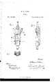
- Figure l is an elevation of the said pump, a portion of the handle being broken'oi;
- Fig. 2 is a side view of the pump;
- Fig. .3 is a section at the line .fr x.
- the pump-barrel a is provided with a piston and rod, a', with the usual valves, and an inlet-coupling, b, and exit-coupling c, for therespective pipes.
- This barrel is attached to the frame by screws d passing through wings or flanges e'and entering the lugs f that projectv from the surface of the frame.
- the flanges e . are of the required size and thickness to furnish the requisite strength, and the lfaces of these anges are trued off on both sides at an equal distance from a plane intersecting the center of the pump, so that the pump can be attached to the frame with the dischargepipe either to the right or to the left, and the position of the center of the pump and the piston-rod to the other parts of the frame will remain unchanged.
- the upper end of the piston-rod a slides through a guide, t', upon the frame, and the extent of downward movement is limited by the screw button or head lo.
- In the piston-rod is an enlargement, in which is a slot receiving a roller or pin in the jaw l at the end of the lever-handle m.
- the bracket n is made to receive the fulcrum-pin of said lever m, said pin being entered from the back ofthe bracket, and the hole does not pass entirely through at the front of the bracket; hence the pin cannot work out of place.
- the frame r is made of corresponding size at each side of the vertical central line, and provided with two sets of bolt-holes, so that the bracket n can be bolted to the frame at o o or at s s, and hence the handle or lever m can stand either to the right or to the left, as most convenient for the position where the pump is to be placed.
- the frame r made with two sets of screw or bolt holes in corresponding positions at opposite sides of the vertical central line, in combination with the bracket n and lever m, the parts being constructed substantially as specified, so as to be changeable from one side of the frame to the other, as set forth.
Landscapes
- Engineering & Computer Science (AREA)
- General Engineering & Computer Science (AREA)
- Mechanical Engineering (AREA)
- Chemical & Material Sciences (AREA)
- Combustion & Propulsion (AREA)
- Details Of Reciprocating Pumps (AREA)
Description
UNITEIJ STATES WILLIAM S.V GARR, OF NEW YORK, N. Y.
IMPROVEMENT IN PUMPS.
Specification forming part of Letters Patent No. 131,663, dated September 24, 1872.
.To all whom fit may concern:
Be it known that I, WILLIAM S. CARR, of the city and State of New York, have invented an Improvement in Pumps; and the following is declared to be a correct description thereof. 'M
In conn eoting pumps to the respective pipes there is a difficulty experienced that the coupling of the pipe is upon the wrong side of the barrel, and hence the pumpcannot be placed in the most convenient position in a building. The same diiiicultiesarise in regard to the lever-handle; hence pumps have to be made right and left handed, to-suit the positions in which they are to be used in buildings; but in cases of alterations the pumps frequently have to be changed.
My present invention is made for the purpose of allowing the parts of the pump to be transposed and thereby adapted to any position where they are to be employed. I make use of a metallic frame carrying the parts of the pump, and said frame is of the same shape at each side of center line, and provided with two sets of holes for the bolts that connect the bracket of the handle or lever7 thus allowing the handle to be attached at either side, and tlie pump is in line with the center of the frame and provided with attaching-lugs that are of equal width on each side of a vertical central plane, so that the pump can be positioned with the discharge pipe leading either to the right or the left, and thereby the entire pump can be adapted to any position where it is to be, placed. y
In the drawing, Figure lis an elevation of the said pump, a portion of the handle being broken'oi; Fig. 2 is a side view of the pump;
y and Fig. .3 is a section at the line .fr x.
The pump-barrel a is provided with a piston and rod, a', with the usual valves, and an inlet-coupling, b, and exit-coupling c, for therespective pipes. This barrel is attached to the frame by screws d passing through wings or flanges e'and entering the lugs f that projectv from the surface of the frame. The flanges e .are of the required size and thickness to furnish the requisite strength, and the lfaces of these anges are trued off on both sides at an equal distance from a plane intersecting the center of the pump, so that the pump can be attached to the frame with the dischargepipe either to the right or to the left, and the position of the center of the pump and the piston-rod to the other parts of the frame will remain unchanged. The upper end of the piston-rod a slides through a guide, t', upon the frame, and the extent of downward movement is limited by the screw button or head lo. In the piston-rod is an enlargement, in which is a slot receiving a roller or pin in the jaw l at the end of the lever-handle m. The bracket n is made to receive the fulcrum-pin of said lever m, said pin being entered from the back ofthe bracket, and the hole does not pass entirely through at the front of the bracket; hence the pin cannot work out of place. The frame r is made of corresponding size at each side of the vertical central line, and provided with two sets of bolt-holes, so that the bracket n can be bolted to the frame at o o or at s s, and hence the handle or lever m can stand either to the right or to the left, as most convenient for the position where the pump is to be placed. l
I claim as my invention- 1.. The pump-barrel a, with anges c e, having both of their faces trued oi1 at equal distances from a plane intersecting the center of the pump, for the purposes set forth.
2. The frame r, made with two sets of screw or bolt holes in corresponding positions at opposite sides of the vertical central line, in combination with the bracket n and lever m, the parts being constructed substantially as specified, so as to be changeable from one side of the frame to the other, as set forth.
WM. S. CARR.
Witnesses:
GEO. T. PINGKNEY, Guns. H. SMITH.
Signed by me this 19th day of March, A. D.
Publications (1)
| Publication Number | Publication Date |
|---|---|
| US131663A true US131663A (en) | 1872-09-24 |
Family
ID=2201080
Family Applications (1)
| Application Number | Title | Priority Date | Filing Date |
|---|---|---|---|
| US131663D Expired - Lifetime US131663A (en) | Improvement in pumps |
Country Status (1)
| Country | Link |
|---|---|
| US (1) | US131663A (en) |
-
0
- US US131663D patent/US131663A/en not_active Expired - Lifetime
Similar Documents
| Publication | Publication Date | Title |
|---|---|---|
| US131663A (en) | Improvement in pumps | |
| US1471520A (en) | Coupling | |
| US38531A (en) | Improvement in water-engines | |
| US179075A (en) | Improvement in stocks for fire-arivjs | |
| US488546A (en) | Thomas doddrell | |
| US649831A (en) | Coupling for pump-rods. | |
| US178057A (en) | Improvement in double-acting force-pumps | |
| US164396A (en) | Improvement in rock-drill tripods | |
| US664947A (en) | Bicycle-pump. | |
| US122669A (en) | Improvement in thill-couplings | |
| US108426A (en) | Improvement in steam-engines | |
| US51936A (en) | Improvement in rotary pumps | |
| US198279A (en) | Improvement in rear sights for fire-arms | |
| US11704A (en) | John tapley | |
| US326597A (en) | seegeaot | |
| US298435A (en) | wolfe | |
| US128635A (en) | Improvement in force-puwips | |
| US68748A (en) | Samuel w | |
| US127087A (en) | Improvement in pump-handle brackets | |
| US854992A (en) | Centering device. | |
| US178225A (en) | Improvement in pumps | |
| US309918A (en) | Adxey t | |
| US125892A (en) | Improvement in apparatus for straightening cylinders | |
| US695110A (en) | Bevel. | |
| US200026A (en) | Improvement in air-pumps |