US1291237A - Pitman connection. - Google Patents
Pitman connection. Download PDFInfo
- Publication number
- US1291237A US1291237A US22978618A US22978618A US1291237A US 1291237 A US1291237 A US 1291237A US 22978618 A US22978618 A US 22978618A US 22978618 A US22978618 A US 22978618A US 1291237 A US1291237 A US 1291237A
- Authority
- US
- United States
- Prior art keywords
- jaws
- pitman
- clamping
- resilient
- connection
- Prior art date
- Legal status (The legal status is an assumption and is not a legal conclusion. Google has not performed a legal analysis and makes no representation as to the accuracy of the status listed.)
- Expired - Lifetime
Links
Images
Classifications
-
- F—MECHANICAL ENGINEERING; LIGHTING; HEATING; WEAPONS; BLASTING
- F16—ENGINEERING ELEMENTS AND UNITS; GENERAL MEASURES FOR PRODUCING AND MAINTAINING EFFECTIVE FUNCTIONING OF MACHINES OR INSTALLATIONS; THERMAL INSULATION IN GENERAL
- F16C—SHAFTS; FLEXIBLE SHAFTS; ELEMENTS OR CRANKSHAFT MECHANISMS; ROTARY BODIES OTHER THAN GEARING ELEMENTS; BEARINGS
- F16C11/00—Pivots; Pivotal connections
- F16C11/04—Pivotal connections
- F16C11/06—Ball-joints; Other joints having more than one degree of angular freedom, i.e. universal joints
- F16C11/0619—Ball-joints; Other joints having more than one degree of angular freedom, i.e. universal joints the female part comprising a blind socket receiving the male part
- F16C11/0623—Construction or details of the socket member
- F16C11/0628—Construction or details of the socket member with linings
- F16C11/0633—Construction or details of the socket member with linings the linings being made of plastics
-
- Y—GENERAL TAGGING OF NEW TECHNOLOGICAL DEVELOPMENTS; GENERAL TAGGING OF CROSS-SECTIONAL TECHNOLOGIES SPANNING OVER SEVERAL SECTIONS OF THE IPC; TECHNICAL SUBJECTS COVERED BY FORMER USPC CROSS-REFERENCE ART COLLECTIONS [XRACs] AND DIGESTS
- Y10—TECHNICAL SUBJECTS COVERED BY FORMER USPC
- Y10T—TECHNICAL SUBJECTS COVERED BY FORMER US CLASSIFICATION
- Y10T403/00—Joints and connections
- Y10T403/32—Articulated members
- Y10T403/32606—Pivoted
- Y10T403/32631—Universal ball and socket
- Y10T403/32786—Divided socket-type coupling
Definitions
- This invention relates to pitman connections for mowers, and like machines,
- This invention has for its object to remedy this condition by providing means utilined in connection with a pitman having tit one or more resilient jaws for preventing this accidental separatlon of the grassward end of the pitman from the bearing member on the mower knife head.
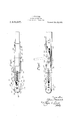
- Figure 1 shows, in plan view, the grass-f ward end of a pitman having my improvements embodied therein;
- Fig. 2 is a side elevation of the construction shown in Fig. 1.
- the body of the pitman is formed preferably of wood, and has secured thereto, at its grassward end, straps or clamping jaws it and 12.. @ne or both of these straps is formed of resilient material in order that scribed may be obtained.
- the straps if and 12 are provided at their grassward ends with spherical bearing portions 13 and i which cooperate with a spherical bearh member 15 formed integral with or seen rigidly to the knife head of the mower
- the straps ii and 12 are slotted, as shown at 3th and l'l, and receive in the slot a re ciprocable jaw clamping and spread member 18. Bearing portions 13 and.
- the straps are provided with outer incli bearing surfaces 19 and 20, which cotipeiaie with oppositely disposed inclined bearing surfaces 21 and 22 formed on the inner faces of the bifurcated outer end of the w clamping member 18.
- the stubbleward, rear end of the clamping member 18, is provided with outer inclined bearing surfaces 23 and 24, which cofiiperate with the inclined bearing surfaces 25 and 26 formed at the stubbleward end of the slots 16 and it.
- the clamping member 13 has a stubblewardly extending shank portion 27 on which is carhid fit
- the shank 2? extends through an aperture in the member 30, and has secured thereto at its stubbleward end a cotter pin 31, which prevents the shank 27 from becoming separated from the member 30.
- the member 30 is also provided with slots 32 and 33 through which the straps 11 and 12 extend, and is pivoted at Set to a ll -sl1aped lever 35, which, in turn, is pivoted at 36 to the body of the pitman.
- the pivotal connections 34 and 36 are dis posed in such a position, and the lever 35 is curved in such a manner, that a toggle locking action is obtained when the lever 35 is forced downwardly against the bodypon tion 10 of the pitman in order to force the jaw clamping member 18 into clamping position.
- This is due to the fact that the pivot 34 between the grassward end of the lever and the il -shaped link 30 is disposed above and out of alinement with a line connecting the pivot 36 with the connection between the cross-portion of member 30 with the shank 27 of the jaw clamping member.
- the lever 35 When it is desired to release the bearing member15 from the pitman, the lever 35 is thrown to the dotted line position shown in Fig. 2, and in this position forces the member through the pin 31 to draw the clamping member 18 rearwardly until the inclined bearing surfaces 23 and 24, acting in conjunction with the bearing surfaces 25 and 26, spread the pitman straps apart, and release the bearing member 15.
- the cross-portion of the member 30 When the lever is in position to force the pitman straps into clamping relation, the cross-portion of the member 30 is in the position shown in full lines in Fig. l, and by means of the slotted connection between this member and the pitman straps the accidental separation of the grass'ward end of. the pitman from the knife head of the mower is prevented.
- hile I have in the above specification detending to prevent the accidental spreading of said jaws when said jaws are in clamping position I 2.
- a pltman having jaws, one'of which is resilient, resilient.
- actuatmg means hav- 3.
- a pitman having jaws, one of which is resilient, reciprocable means for'forcing'one of said jaws toward the other of said jaws, and means for preventing the spreading of saidjaws when said aws are in clamping position.
- apitman havingmg aws, one of which is resilient means for forcing one of said jaws toward the other of said jaws, and means for preventing the spreading of said jaws when said jaws are in clamping position.
- a pitman having jaws, one of which is resilient, reciprocable aw clamping means, resilient means for forcing said jaws into clamping position, said last named means having means for preventing accidental spreading of said jaws when said jaws are in clamping position.
- a pitman having means for preventin the accidental spreading of said jaws w en said jaws are in clamping position.
- a pitman having resilient jaws, reciprocable means for clamping and spreading said jaws, resilient means for actuating said reciprocable means, said actuatin means having means for preventing acci ental spreading of said jaws when said jaws are in clamping position.
- a pitman having resilient jaws, a jaw clamping and spreading member having a stubblewardly extending shank portion, means including a link member cooperating with said shank portion. for reciprocatin said clamping and spreading member, said Iink member having means cooperating with said resilient jaws for preventing accidental spreading of the same when sald jaws are in clamping position.
- a pitman having resilient jaws, means for clamping said jaws, and means including a link member for operating said clamping means and for preventing accidental spreading of said jaws when said jaws are in clamping position.
- a pitman having resilient jaws, a jaw clamping member, and means including a slotted link for actuating said jaw clamping member and for preventing accidental spreading of said jaws when said jaws are in clamping position.
- a pitman having resilient jaws, a jaw clamping member, and means including a slotted link for actufating said jaw clamping member and for preventing accidental spreading of said jaws when said jaws are in clamping position, the end against the jaw clamping member, slots of said actuating member receiving said means for preventing the operation of said 10 j ELWS. link member and said shank portion, and 12..
Landscapes
- Engineering & Computer Science (AREA)
- General Engineering & Computer Science (AREA)
- Mechanical Engineering (AREA)
- Harvester Elements (AREA)
Description
J. STURHOCK.
PITMAN CONNECTION.
APPLICATION FILED APR. 20. 1918.
9 1 9 .IIM 4 1 m J m m l pm tilt till
ii at iii, ii
pennant,
specification at Letters lt'atent.
Patented darn Ital,
application filed .tlprll t0, with. tterial No. .tttt'ttd.
To all whom it may concern Be It known that l, dorrn @rnnnoon, a subject of the King of Great Britain, re-
siding at Chicago, in the county of Cook 1 and btate of llllinois, have invented certain new and useful improvements in Pitman Connections, of which the following is a full, clear, and. exact specification.
This invention relates to pitman connections for mowers, and like machines,
Tn the use of pitmen having one or more resilient straps or jaws to clamp the bearing member of the knife of the mower knife head, it has been found that the grassward lend of the pitman has, in some instances,
been accidentally pulled away from or separated from the knife head. This accidental separating of the grassward end of the pit man from the bearing member on the end of the knife head has occurred in some iii-- stances when the mower knives have en countered some tough or unyielding object, such, for instance, as a stick or stone. This object, in such instances, prevents the reciprocation of the knives, and as the crank disk continues to revolve the pitman is pulled away from the knife head, and the bearing is snapped from the clamping jaws.
This invention has for its object to remedy this condition by providing means utilined in connection with a pitman having tit one or more resilient jaws for preventing this accidental separatlon of the grassward end of the pitman from the bearing member on the mower knife head.
Figure 1 shows, in plan view, the grass-f ward end of a pitman having my improvements embodied therein; and,
Fig. 2 is a side elevation of the construction shown in Fig. 1.
The body of the pitman is formed preferably of wood, and has secured thereto, at its grassward end, straps or clamping jaws it and 12.. @ne or both of these straps is formed of resilient material in order that scribed may be obtained. The straps if and 12 are provided at their grassward ends with spherical bearing portions 13 and i which cooperate with a spherical bearh member 15 formed integral with or seen rigidly to the knife head of the mower The straps ii and 12 are slotted, as shown at 3th and l'l, and receive in the slot a re ciprocable jaw clamping and spread member 18. Bearing portions 13 and. it t the straps are provided with outer incli bearing surfaces 19 and 20, which cotipeiaie with oppositely disposed inclined bearing surfaces 21 and 22 formed on the inner faces of the bifurcated outer end of the w clamping member 18. The stubbleward, rear end of the clamping member 18, is provided with outer inclined bearing surfaces 23 and 24, which cofiiperate with the inclined bearing surfaces 25 and 26 formed at the stubbleward end of the slots 16 and it. The clamping member 13 has a stubblewardly extending shank portion 27 on which is carhid fit
a shoulder 29 on member 13, at its gras ward end, and at its rear end spring 23 bears against a ll-shaped link 30. The shank 2? extends through an aperture in the member 30, and has secured thereto at its stubbleward end a cotter pin 31, which prevents the shank 27 from becoming separated from the member 30. The member 30 is also provided with slots 32 and 33 through which the straps 11 and 12 extend, and is pivoted at Set to a ll -sl1aped lever 35, which, in turn, is pivoted at 36 to the body of the pitman. The pivotal connections 34 and 36 are dis posed in such a position, and the lever 35 is curved in such a manner, that a toggle locking action is obtained when the lever 35 is forced downwardly against the bodypon tion 10 of the pitman in order to force the jaw clamping member 18 into clamping position. This is due to the fact that the pivot 34 between the grassward end of the lever and the il -shaped link 30 is disposed above and out of alinement with a line connecting the pivot 36 with the connection between the cross-portion of member 30 with the shank 27 of the jaw clamping member.
Having described the construction of my till Mill
llllli improved pitman connection, I will now briefly set forth the operation of the same.
In full lines in Figs. 1 and 2, I have shown .the jaw clamping member in clamping position, the lever 35 being pressed downwardly until its cross-portion is in contact with the body of the pitman. In this position the I member 30 is forced in a grassward direction, compressing the spring 28, and through this spring forcing the jaw clampmg member 18 into clamping position,'thereby forcing the bearing portions 13 and lfl of the pitman straps l1 and 12 into bearing contact with the bearing member 15 on the mower knife head. It should be-noted that this resilient clamping action automatically takes up the wear between the bearing portions 13 and 14, and the bearing member 15.
When it is desired to release the bearing member15 from the pitman, the lever 35 is thrown to the dotted line position shown in Fig. 2, and in this position forces the member through the pin 31 to draw the clamping member 18 rearwardly until the inclined bearing surfaces 23 and 24, acting in conjunction with the bearing surfaces 25 and 26, spread the pitman straps apart, and release the bearing member 15. When the lever is in position to force the pitman straps into clamping relation, the cross-portion of the member 30 is in the position shown in full lines in Fig. l, and by means of the slotted connection between this member and the pitman straps the accidental separation of the grass'ward end of. the pitman from the knife head of the mower is prevented.
From the above description it willbe seen that I have provided a simple and easily operated construction for connecting the pitman to the knife head of the mower in such a manner that the wear between the cooperating parts will be automatically taken up,
' and that accidental separation of the cooperaltin parts is efl'ectively prevented. 1
hile I have in the above specification detending to prevent the accidental spreading of said jaws when said jaws are in clamping position I 2. In a pitman connectlon, a pltman having jaws, one'of which is resilient, resilient.
means for forcing one of said jaws toward the other aw, and means for actuat1ng'sa1d last named means, said actuatmg means hav- 3. In a pitman connection, a pitman having jaws, one of which is resilient, reciprocable means for'forcing'one of said jaws toward the other of said jaws, and means for preventing the spreading of saidjaws when said aws are in clamping position.
4. In a pitman connection, apitman havmg aws, one of which is resilient means for forcing one of said jaws toward the other of said jaws, and means for preventing the spreading of said jaws when said jaws are in clamping position.
5. In a pitman connection, a pitman having jaws, one of which is resilient, reciprocable aw clamping means, resilient means for forcing said jaws into clamping position, said last named means having means for preventing accidental spreading of said jaws when said jaws are in clamping position.
. 6. In a pitman connection, a pitman havmg aws, one of which is resilient, means for forcing one of said jaws toward and away from the other of said jaws, means for actuating said last named means, said actuating means having means for preventin the accidental spreading of said jaws w en said jaws are in clamping position.
7. In a pitman connection, a pitman having resilient jaws, reciprocable means for clamping and spreading said jaws, resilient means for actuating said reciprocable means, said actuatin means having means for preventing acci ental spreading of said jaws when said jaws are in clamping position.
8. In a pitman connection, a pitman having resilient jaws, a jaw clamping and spreading member having a stubblewardly extending shank portion, means including a link member cooperating with said shank portion. for reciprocatin said clamping and spreading member, said Iink member having means cooperating with said resilient jaws for preventing accidental spreading of the same when sald jaws are in clamping position.
9. In a pitman connection, a pitman having resilient jaws, means for clamping said jaws, and means including a link member for operating said clamping means and for preventing accidental spreading of said jaws when said jaws are in clamping position.
10. In a pitman connection, a pitman having resilient jaws, a jaw clamping member, and means including a slotted link for actuating said jaw clamping member and for preventing accidental spreading of said jaws when said jaws are in clamping position.
11. In a pitman connection, a pitman having resilient jaws, a jaw clamping member, and means including a slotted link for actufating said jaw clamping member and for preventing accidental spreading of said jaws when said jaws are in clamping position, the end against the jaw clamping member, slots of said actuating member receiving said means for preventing the operation of said 10 j ELWS. link member and said shank portion, and 12.. lln a pitman connection, a pitman havmeans for reciprocating said link member ing resilient jaws, a jaW clamping member said link member having slots receiving said having a shank portion, a spring carried by resilient jaws, said shank portion, and bearing at one end lln testimony vvl ereot l atfix my signature. 15 against a link member and at its opposite JUHN S'NIRJRWUK. Y
Priority Applications (1)
| Application Number | Priority Date | Filing Date | Title |
|---|---|---|---|
| US22978618A US1291237A (en) | 1918-04-20 | 1918-04-20 | Pitman connection. |
Applications Claiming Priority (1)
| Application Number | Priority Date | Filing Date | Title |
|---|---|---|---|
| US22978618A US1291237A (en) | 1918-04-20 | 1918-04-20 | Pitman connection. |
Publications (1)
| Publication Number | Publication Date |
|---|---|
| US1291237A true US1291237A (en) | 1919-01-14 |
Family
ID=3358796
Family Applications (1)
| Application Number | Title | Priority Date | Filing Date |
|---|---|---|---|
| US22978618A Expired - Lifetime US1291237A (en) | 1918-04-20 | 1918-04-20 | Pitman connection. |
Country Status (1)
| Country | Link |
|---|---|
| US (1) | US1291237A (en) |
Cited By (3)
| Publication number | Priority date | Publication date | Assignee | Title |
|---|---|---|---|---|
| US2776152A (en) * | 1950-10-18 | 1957-01-01 | Anthony P Ianuzzi | Ball and socket joints |
| US2837357A (en) * | 1955-03-29 | 1958-06-03 | Massey Harris Ferguson Inc | Pitman connection |
| US3106963A (en) * | 1960-12-01 | 1963-10-15 | Kaman Aircraft Corp | Rotor for a helicopter |
-
1918
- 1918-04-20 US US22978618A patent/US1291237A/en not_active Expired - Lifetime
Cited By (3)
| Publication number | Priority date | Publication date | Assignee | Title |
|---|---|---|---|---|
| US2776152A (en) * | 1950-10-18 | 1957-01-01 | Anthony P Ianuzzi | Ball and socket joints |
| US2837357A (en) * | 1955-03-29 | 1958-06-03 | Massey Harris Ferguson Inc | Pitman connection |
| US3106963A (en) * | 1960-12-01 | 1963-10-15 | Kaman Aircraft Corp | Rotor for a helicopter |
Similar Documents
| Publication | Publication Date | Title |
|---|---|---|
| US1291237A (en) | Pitman connection. | |
| US1196524A (en) | Mower-pitman. | |
| US879064A (en) | Shears or scissors. | |
| US615956A (en) | Bolt-clipper | |
| US220696A (en) | Improvement in pitmen for harvesters | |
| US227393A (en) | Pitman-connection | |
| US210646A (en) | Improvement in pitman-connections | |
| US297882A (en) | John waggonneb | |
| US106339A (en) | Improvement in pitman-connections for harvesters | |
| US311996A (en) | Pitman for mowing-machines | |
| US422914A (en) | Frank casto | |
| US561000A (en) | John h | |
| US151861A (en) | Improvement in pitman-couplings | |
| US357749A (en) | Hieam m | |
| US396291A (en) | William richard | |
| US55781A (en) | Improvement in harvesters | |
| US1312280A (en) | Pitman connection. | |
| US234090A (en) | Adjustable wrist-pin | |
| US2548055A (en) | Automatic pitman bar connection | |
| US115273A (en) | Improvement in clamps for thill-couplings | |
| US985906A (en) | Pitman connection. | |
| US234250A (en) | Animal-shears | |
| US140312A (en) | Improvement in pitman connections | |
| US2837357A (en) | Pitman connection | |
| US602586A (en) | morris |